EP1389733B1 - Shimming an MRI magnet assembly - Google Patents
Shimming an MRI magnet assembly Download PDFInfo
- Publication number
- EP1389733B1 EP1389733B1 EP03254496A EP03254496A EP1389733B1 EP 1389733 B1 EP1389733 B1 EP 1389733B1 EP 03254496 A EP03254496 A EP 03254496A EP 03254496 A EP03254496 A EP 03254496A EP 1389733 B1 EP1389733 B1 EP 1389733B1
- Authority
- EP
- European Patent Office
- Prior art keywords
- magnetic field
- shim
- shims
- magnetic
- field generating
- Prior art date
- Legal status (The legal status is an assumption and is not a legal conclusion. Google has not performed a legal analysis and makes no representation as to the accuracy of the status listed.)
- Expired - Lifetime
Links
- 239000000696 magnetic material Substances 0.000 claims description 40
- 230000000712 assembly Effects 0.000 claims description 29
- 238000000429 assembly Methods 0.000 claims description 29
- 238000000034 method Methods 0.000 claims description 15
- 230000004907 flux Effects 0.000 claims description 7
- 230000002708 enhancing effect Effects 0.000 claims 2
- 230000005415 magnetization Effects 0.000 claims 2
- 238000002595 magnetic resonance imaging Methods 0.000 description 26
- 239000000463 material Substances 0.000 description 11
- 241000239290 Araneae Species 0.000 description 6
- CWYNVVGOOAEACU-UHFFFAOYSA-N Fe2+ Chemical compound [Fe+2] CWYNVVGOOAEACU-UHFFFAOYSA-N 0.000 description 2
- 238000003384 imaging method Methods 0.000 description 2
- 239000010410 layer Substances 0.000 description 2
- 238000004519 manufacturing process Methods 0.000 description 2
- XEEYBQQBJWHFJM-UHFFFAOYSA-N Iron Chemical group [Fe] XEEYBQQBJWHFJM-UHFFFAOYSA-N 0.000 description 1
- BZHJMEDXRYGGRV-UHFFFAOYSA-N Vinyl chloride Chemical compound ClC=C BZHJMEDXRYGGRV-UHFFFAOYSA-N 0.000 description 1
- 239000000853 adhesive Substances 0.000 description 1
- 230000001070 adhesive effect Effects 0.000 description 1
- 238000010276 construction Methods 0.000 description 1
- 230000003247 decreasing effect Effects 0.000 description 1
- 230000007812 deficiency Effects 0.000 description 1
- 230000001747 exhibiting effect Effects 0.000 description 1
- 239000011152 fibreglass Substances 0.000 description 1
- 239000000945 filler Substances 0.000 description 1
- 239000011347 resin Substances 0.000 description 1
- 229920005989 resin Polymers 0.000 description 1
- 238000007493 shaping process Methods 0.000 description 1
- 239000002356 single layer Substances 0.000 description 1
- 125000006850 spacer group Chemical group 0.000 description 1
- 230000003068 static effect Effects 0.000 description 1
Images



Classifications
-
- G—PHYSICS
- G01—MEASURING; TESTING
- G01R—MEASURING ELECTRIC VARIABLES; MEASURING MAGNETIC VARIABLES
- G01R33/00—Arrangements or instruments for measuring magnetic variables
- G01R33/20—Arrangements or instruments for measuring magnetic variables involving magnetic resonance
- G01R33/28—Details of apparatus provided for in groups G01R33/44 - G01R33/64
- G01R33/38—Systems for generation, homogenisation or stabilisation of the main or gradient magnetic field
- G01R33/387—Compensation of inhomogeneities
- G01R33/3873—Compensation of inhomogeneities using ferromagnetic bodies ; Passive shimming
Definitions
- This invention relates to magnetic field shimming systems. More particularly, the invention relates to magnetic field shimming systems for magnetic resonance imaging (MRI) magnet assemblies.
- MRI magnetic resonance imaging
- MRI magnet assemblies require an air gap large enough to receive all or part of an object to be scanned, and typically require an intensive, uniform magnetic field exhibiting an accuracy on the order of 10 parts per million (ppm) in a specified imaging volume within the air gap.
- ppm parts per million
- open geometry MRI One known configuration of an MRI magnet assembly is known as open geometry MRI.
- open geometry MRI comprises opposing magnetic field generating assemblies connected to each other by one or more yokes or support members.
- cylindrical geometry MRI Another known configuration is known as cylindrical geometry MRI, in which magnetic field generating assemblies and other magnetic field shaping components are arranged around a cylindrical structure.
- the magnetic field in an MRI magnet assembly is typically created using permanent magnets, electromagnets, or a combination of the two.
- one known MRI magnet assembly has a structure in which magnetic pole pieces are fixed facing each other at one end of each of a pair of permanent magnet structures in which an R--Fe--B-based magnet is used as the magnetic field generating element, the other ends are coupled by a yoke, and a static magnetic field is generated within the air gap between the magnetic pole pieces.
- Another known MRI magnet assembly has electromagnetic coils (including resistive coils, superconducting coils, and the like) wound around air or iron cores for the magnetic field generating element in place of the above- mentioned permanent magnet structures.
- the uniformity of the magnetic field is greatly influenced by many factors. These factors include: the properties of the materials used in constructing the MRI magnet, the accuracy of manufacturing the MRI magnet, and the environment in which the MRI magnet is placed. Often times, variations in these and other factors result in an inhomogeneous field, ranging from several hundred ppm to several thousand ppm. To obtain the required uniformity for useful imaging, this field inhomogeneity must be corrected.
- One method of correcting field inhomogeneity is to apply shims constructed of magnetic (e.g., ferrous) material and/or permanent magnetic material to opposing surfaces formed on the magnetic field generating assemblies.
- magnetic e.g., ferrous
- shims constructed of magnetic (e.g., ferrous) material and/or permanent magnetic material to opposing surfaces formed on the magnetic field generating assemblies.
- MRI-dedicated magnetic field generating device for generating magnetic fields within an air gap, including: a pair of permanent magnet assemblies opposite to each other to form an air gap therebetween; yokes for magnetically linking the permanent magnet assemblies; and magnetic pole pieces fixed to air-gap-confronting surfaces thereof.
- intensities of the magnetic fields are increased by disposing a plurality of magnetic material segments on the same circle or a concentric circle on the opposing surfaces of the pole pieces or decreased by disposing a plurality of permanent magnet segments having a magnetizing direction opposite to that of the permanent magnet assemblies on the same circle or the concentric circle on the opposing surfaces of the pole pieces; or alternatively both the magnetic material segments and the permanent magnet segments are disposed on the same circle or the concentric circle.
- shims for MRI magnet assemblies in which the shims comprise adjustably positionable permanent magnets and/or magnetic materials are described in WO-A-01 55732 , US-B-6 351 125 and EP-A-0 626 587 .
- the shims are arranged along a plurality of concentric geometric shapes each having at least five sides.
- the shims are arranged in a plurality of rows and columns, where the rows are normal to the columns.
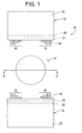
- the MRI magnet assembly 10 includes opposing magnetic field generating assemblies 12, which generate a magnetic field within an air gap 14 formed between the assemblies 12. Disposed on each of the opposing surfaces 16 of the magnetic field generating assemblies 12 is a plurality of shims 18 arranged to correct inhomogeneities in the magnetic field.
- the magnetic field generating assemblies 12 may be coupled by one or more yokes or support members (not shown).
- the magnetic field generating assemblies 12 may include any type of arrangement for generating a magnetic field in the air gap 14 where opposing surfaces 16 are provided for receiving shims 18 to correct inhomogeneities in the magnetic field.
- each magnetic field generating assembly 12 may include the magnetic pole piece 20 fastened to one or more magnetic field generating elements 22 and a gradient plate 21 fastened to the magnetic pole piece 20, where opposing surfaces 16 are formed on the opposing surfaces of the gradient plates 21.
- Such an arrangement is described, for example, in U.S. Patent No. 6,275,128 , entitled "MRI Magnetic Field Generator".
- each magnetic field generating assembly 12 may include a magnetic pole piece 20 fastened to one or more magnetic field generating elements 22 with no gradient plate 21, where opposing surfaces 16 are defined on the opposing surfaces of the magnetic pole pieces 20.
- a magnetic pole piece 20 fastened to one or more magnetic field generating elements 22 with no gradient plate 21, where opposing surfaces 16 are defined on the opposing surfaces of the magnetic pole pieces 20.
- the magnetic field generating assemblies 12 may have no pole pieces 20 or gradient plates 21, with the opposing surfaces 14 being defined on the magnetic field generating elements 22.
- the magnetic field generating elements 22 may include permanent magnets, electromagnets (e.g., resistive coils, superconducting coils, and the like), or a combination of the two.
- Each shim 18 may be constructed of a magnetic (e.g., ferrous) material or a permanently magnetic material.
- shims 18 are secured to directly to surface 16.
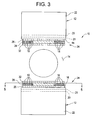
- shims 18 may be secured to surface 16 using a shim holder 24, as shown in FIGs. 2-4 .
- the shim holder 24 may consist of a three-layer, non- magnetic, thin disk, structure including a base disk 26, a holder disk 28 in which have been made holes or slots 30 that serve as pits for accommodating shims 18, and a cover disk 32.
- the slots 30 that hold the shims 18 are made in the holder disk 28 in a predefined pattern, as will be discussed in further detail hereinafter.
- Shim holder 24 may be constructed, for example, from a vinyl chloride resin, glass fiber reinforced plastic, or another such non-magnetic material.
- the shim holder 24 may comprise a two-layer structure including holder disk 28, and cover disk 32.
- the shim holder 24 may comprise a single-layer structure with slots 30 disposed in holder disk 28.
- the shims are directly secured to the shim holder 24.
- slots 30 may be sized to provide an interference fit between the holder disk 28 and the shims 18. The interference fit between the holder disk 28 and shims 18 provides sufficient friction to stop shim 18 from moving out of the slots 30 under the force of the magnetic field.
- shims may be secured to shim holder 24 using an adhesive.
- the shim holder 24 may be structured such that the various disks 26, 28 and 32 are suitably disposed and secured in place.
- the magnetic material shims 18 or permanent magnet shims 18 for adjusting the magnetic field uniformity are inserted into the required slots 30, and if needed, filler material or spacers (not shown) are placed in the gaps between the shims 18 and the cover disk 32 and/or between the shims 18 and the holder disk 28, after which the cover disk 32 is attached to hold everything together.
- the resulting shim holder 24 is aligned with and fastened to the surface 16.
- the magnetic material shims 18 or permanent magnet shims 18 are secured in the required slots 30, and the resulting shim holder 24 is aligned with and fastened to the surface 16.
- FIG. 5 a plan view of surface 16 is shown having a spider web geometry grid pattern 50 superimposed thereon.
- Surface 16 of FIG. 5 may be an upper or lower magnetic field generating assembly 12 ( FIGs. 1 , 3 , and 4 ).
- the spider web geometry grid pattern 50 is depicted as a two-dimensional grid formed in a plane extending along the surface 16.
- the grid is formed from a plurality of concentric geometric shapes 52, each having at least five sides, and a plurality of lines 54 radiating from a common center 56 of the geometric shapes 52.
- the concentric geometric shapes 52 are octagons; however, the concentric geometric shapes could be pentagons, hexagons, heptagons, etc.
- the shims 18 are placed relative to the grid pattern 50. That is, the shims 18 may be placed at the intersections between the radiating lines 54 and the geometric shapes 52, or in the foursided polygons 57 defined by the radiating lines 54 and the geometric shapes 52, resulting in a plurality of shims arranged along the plurality of concentric geometric shapes. Discontinuities in the grid pattern 50 are provided for fasteners 58, as may be needed, for example, for mounting the shim holder 24 to the surface 16 formed on the gradient plate 21 in the embodiments of FIGs. 2-4 .
- slots 30 accommodate shims 18.
- shims 18 may be adhered onto the surfaces 16 in the spider web geometry grid pattern 50.
- the shim holder 24 may be constructed by superimposing the spider web geometry grid pattern 50 on the holder disk 28 and disposing slots 30 in holder disk 28 at the intersections or in the four sided polygons 57 in the grid pattern 50.
- a plan view of a surface 16 is shown having a lattice geometry grid pattern 70 superimposed thereon.
- the lattice geometry grid pattern 70 is an alternative geometry to the spider web geometry grid pattern 50 of FIG. 5 .
- Surface 16 may be on an upper or lower magnetic field generating assembly 12 ( FIGs. 1 , 3 , and 4 ).
- the lattice geometry grid pattern 70 is depicted as a two-dimensional grid formed in a plane extending along the surface 16.
- the grid pattern 70 is formed from a plurality of equally spaced, parallel lines 72 forming columns, and a plurality of, parallel lines 76 extending normal to the parallel lines 72 forming rows.
- the shims 18 are placed relative to the grid pattern 70.
- the shims 18 are placed at the intersections or inside the rectangles formed by the grid pattern 70 to form rows and columns of shims 18. Discontinuities in the grid pattern 70 are provided for fasteners 58, as may be needed, for example, for mounting the shim holder 24 to the surface 16 formed on the gradient plate 21 in the embodiments of FIGs. 2-4 .
- shims 18 may be adhered onto the surfaces 16 in the lattice geometry grid pattern 70.
- the shim holder 24 may be constructed by superimposing the lattice geometry grid pattern 70 on the holder disk 28 and disposing slots 30 in holder disk 28 at the intersections or inside the rectangles in the grid pattern 70. Slots 30 accommodate shims 15.
- permanent magnet and magnetic material shims 18 may be applied to correct inhomogeneities in the magnetic field created by magnetic field generating assemblies 12.
- the material of the shims 18 may be different at different regions in the grid.
- permanent magnet shims 18 may be positioned in some regions of the grid, while magnetic material shims 18 are positioned at others.
- inhomogeneities in the magnetic field are corrected by varying the amount of material used in the shims 18 at different regions in the grid. For example, shims 18 having less material may be positioned in some regions of the grid, while shims 18 having more material are positioned at others.
- the shims 18 may be arranged such that their magnetizing direction is in line with, or opposite to the magnetizing direction of the respective magnetic field generating assembly 12, as needed to make the distribution of the magnetic field uniform.
- Each of these configurations may be applied separately or in combination.
- the magnetic field created by magnetic field generating assemblies 12 is greatly influenced by, among other things, the accuracy used in manufacturing the MRI magnet and the environment in which the MRI magnet is placed, correction of the inhomogeneities in the magnetic field is usually performed for each individual MRI magnet assembly after it has been installed in the environment in which it is to be used (e.g., a hospital or laboratory).
- This correction can be accomplished using any known method to determine the appropriate shim 18 configuration(s) needed to ensure a uniform magnetic field.
- a linear programming method such as described in U.S. Patent No. 5,760,585 , entitled “Method for Actively and Passively Shimming A Magnet”
- a harmonic shimming method such as described in U.S. Patent No. 5,623,430 , entitled “Method for Passively Shimming An Open Magnet” may be used.
- shim 18 may be constructed of magnetic or permanent magnetic material, as needed to correct inhomogeneities in the magnetic field. Where shim 18 is constructed of permanent magnet material, the shim 18 may be positioned relative to surface 16 using any known arrangement. However, where shim 18 is constructed of magnetic material, it is preferred that shim 18 is arranged as shown in FIG. 7 .
- Magnetic material shim 18 is a flat, rectangular plate having a top edge 80, a bottom edge 82, side edges 84, 86, and opposing face surfaces 88, 90.
- Bottom edge 82 is positioned proximate to surface 16
- top edge 80 is positioned distal from surface 16 such that face surfaces 88 and 90, which have the largest surface area, are aligned with the direction of the magnetic field generated by magnetic field generating assembly 12, which is indicated by arrow 98.
- FIGs. 1 In the embodiment of FIGs.
- a magnetic material shim 18 is arranged such that bottom edge 82 contacts base disk 26 and top edge 80 contacts cover disk 32; in the embodiment of FIG. 4 , side edges 84, 86 and opposing faces surfaces 88, 90 are captured by holder disk 28 with bottom edge 82 proximate surface 16; and in the embodiment of FIG. 1 , bottom edge 82 is adhered to surface 16.
- Magnetic flux induced in the magnetic material shim 18 is indicated by lines 92, which extend a distance x from top edge 80.
- the arrangement of magnetic material shim 18 is different than that used in the prior art, which is shown in FIGs. 8A and 8B .
- the face 88 of shim 18 is positioned proximate to surface 16, such that the plate-shaped shim 18 lies flat against surface 16.
- the prior art arrangement will induce a magnetic flux, as indicated by lines 94, which extends a distance y from the surface 90 of the magnetic material shim 15.
- the distance y that the magnetic flux extends from the magnetic material shim 18 arranged as in FIGs. 8A and 8B is less than the distance x that the magnetic flux extends from the magnetic material shim 18 arranged as in FIG. 7 .
- the magnetic material shim 18 arranged as in FIGs. 8A and 8B provides a weaker magnetic field than the magnetic material shim 18 arranged as in FIG. 7 .
- the top edge 80 has a much smaller surface area than the surface 90, the magnetic material shim 18 as arranged in FIG. 7 is much more easily magnetized than the magnetic material shim 18 as arranged in FIGs. 8A and 8B .
- a greater concentration of magnetic flux extends a greater distance into the region of interest for reducing the inhomogeneities in the magnetic field. Because the arrangement of FIG.
- FIG. 7 provides stronger field that extends a greater distance from the magnetic material shim 18, the size of magnetic material shims 18 may be reduced to less than that possible with the prior art arrangement of FIGs. 8A and 8B . Furthermore, because a magnetic material shim 18 tends to align the faces having the largest surface area with the main magnetic field (minimum energy state), the configuration of FIG. 7 places the magnetic material shims 18 in a more stable state, thereby reducing the effort and care that must be taken during the shimming process. As a result, the time to complete the shimming process is reduced below that possible with the shim arrangements of the prior art. Thus, using the shim arrangement of FIG. 7 results in less shim material, reduced shim cost, less shim weight, shorter shimming time than that possible with the prior art arrangement.
- a plurality of magnetic material shims 18 are arranged on surface 16 using the configuration of FIG. 7 .
- magnetic material shims 18 may be coupled together in groups, with each magnetic material shim 18 having its bottom edge 82 proximate surface 16.
- the height h and the width w of the magnetic material shims 18 may be varied as needed to reduce the inhomogeneities in the magnetic field induced by the magnetic field generating assemblies 12.
- the height h being the distance between the top edge 80 and the bottom edge 82, and the width w being the distance between side edges 84 and 86.
Landscapes
- Physics & Mathematics (AREA)
- Condensed Matter Physics & Semiconductors (AREA)
- General Physics & Mathematics (AREA)
- Magnetic Resonance Imaging Apparatus (AREA)
Applications Claiming Priority (2)
| Application Number | Priority Date | Filing Date | Title |
|---|---|---|---|
| US10/064,589 US6984982B2 (en) | 2002-07-29 | 2002-07-29 | Method and system for shimming an MRI magnet assembly |
| US64589 | 2002-07-29 |
Publications (3)
| Publication Number | Publication Date |
|---|---|
| EP1389733A2 EP1389733A2 (en) | 2004-02-18 |
| EP1389733A3 EP1389733A3 (en) | 2005-03-16 |
| EP1389733B1 true EP1389733B1 (en) | 2011-09-14 |
Family
ID=30769098
Family Applications (1)
| Application Number | Title | Priority Date | Filing Date |
|---|---|---|---|
| EP03254496A Expired - Lifetime EP1389733B1 (en) | 2002-07-29 | 2003-07-18 | Shimming an MRI magnet assembly |
Country Status (4)
| Country | Link |
|---|---|
| US (1) | US6984982B2 (https=) |
| EP (1) | EP1389733B1 (https=) |
| JP (1) | JP4424650B2 (https=) |
| CN (1) | CN100565235C (https=) |
Families Citing this family (16)
| Publication number | Priority date | Publication date | Assignee | Title |
|---|---|---|---|---|
| US7081752B2 (en) * | 2003-04-04 | 2006-07-25 | General Electric Company | System and method of electrically loading radio-frequency coils using conductive polymers |
| WO2005037101A1 (ja) * | 2003-10-15 | 2005-04-28 | Hitachi Medical Corporation | 磁気共鳴イメージング装置 |
| GB2414080B (en) * | 2004-05-14 | 2006-07-26 | Oxford Magnet Tech | Tool and method for shimming a magnet |
| US7755359B2 (en) * | 2004-05-31 | 2010-07-13 | Hitachi Medical Corporation | Magnetic resonance imaging apparatus with noise suppressing structure |
| JP4639948B2 (ja) * | 2005-05-17 | 2011-02-23 | 三菱電機株式会社 | 磁石装置及びそれを用いた磁気共鳴イメージング装置 |
| JP4188387B2 (ja) * | 2006-06-05 | 2008-11-26 | ジーイー・メディカル・システムズ・グローバル・テクノロジー・カンパニー・エルエルシー | 磁気共鳴イメージング装置及びシム値設定方法 |
| JP4368909B2 (ja) * | 2007-05-25 | 2009-11-18 | 三菱電機株式会社 | 超電導マグネットの磁場調整装置及び磁場調整方法 |
| JP5349177B2 (ja) * | 2009-07-09 | 2013-11-20 | 株式会社東芝 | 磁気共鳴イメージング装置 |
| JP5627415B2 (ja) * | 2010-11-24 | 2014-11-19 | 三菱電機株式会社 | Mri用超電導マグネットの調整方法 |
| ITGE20120059A1 (it) * | 2012-06-22 | 2013-12-23 | Esaote Spa | Metodo per la correzione della disomogeneità del campo magnetico statico generato dal magnete di una macchina mri e dispositivo per l'attuazione di tale metodo |
| CN103713269A (zh) * | 2012-09-29 | 2014-04-09 | 西门子(深圳)磁共振有限公司 | 用于磁体的匀场片、匀场条以及磁体和磁共振系统 |
| JP6259303B2 (ja) * | 2014-02-04 | 2018-01-10 | 株式会社日立製作所 | 磁石装置および磁気共鳴撮像装置 |
| CN105652225B (zh) * | 2015-12-28 | 2019-01-25 | 沈阳东软医疗系统有限公司 | 一种磁共振系统的匀场方法和装置 |
| CA3123142A1 (en) * | 2016-03-22 | 2017-09-28 | Hyperfine Research, Inc. | Methods and apparatus for magnetic field shimming |
| AU2019274404A1 (en) * | 2018-05-21 | 2020-11-12 | Hyperfine Operations, Inc. | B0 magnet methods and apparatus for a magnetic resonance imaging system |
| DE102019212508A1 (de) | 2019-08-21 | 2021-02-25 | Bruker Switzerland Ag | Temperiersystem für MR-Geräte mit Permanentmagnetanordung |
Family Cites Families (25)
| Publication number | Priority date | Publication date | Assignee | Title |
|---|---|---|---|---|
| US5235284A (en) * | 1989-07-07 | 1993-08-10 | Mitsubishi Denki Kabushiki Kaisha | Passive shim arrangement for nuclear magnetic resonance |
| JPH03131234A (ja) | 1989-07-07 | 1991-06-04 | Sumitomo Special Metals Co Ltd | Mri用磁界発生装置 |
| US5220302A (en) * | 1990-01-22 | 1993-06-15 | The University Of Texas System Board Of Regents | Nmr clinical chemistry analyzer and method of forming a shield |
| JPH07106155A (ja) | 1993-05-26 | 1995-04-21 | General Electric Co <Ge> | C字形超伝導磁石 |
| US5446434A (en) | 1994-07-27 | 1995-08-29 | General Electric Company | Magnet having pole faces with trapezoidal-shaped shims |
| US5635839A (en) * | 1994-11-04 | 1997-06-03 | Picker International, Inc. | High order passive shimming assembly for MRI magnets |
| US5532597A (en) * | 1994-11-04 | 1996-07-02 | Picker International, Inc. | Passive shimming technique for MRI magnets |
| US5550472A (en) * | 1995-04-13 | 1996-08-27 | Picker International, Inc. | Combined radio frequency coil with integral magnetic field shim set |
| KR100373577B1 (ko) * | 1997-12-26 | 2003-02-26 | 스미토모 도큐슈 긴조쿠 가부시키가이샤 | 자기 공명 촬영 장치용 자계 발생 장치 |
| US6011396A (en) * | 1998-01-02 | 2000-01-04 | General Electric Company | Adjustable interventional magnetic resonance imaging magnet |
| US5883558A (en) * | 1998-02-19 | 1999-03-16 | General Electric Company | Open superconductive magnet having shielding |
| US5994991A (en) * | 1998-02-19 | 1999-11-30 | General Electric Company | Open magnet having shielding |
| GB2337595B (en) * | 1998-05-22 | 2003-03-19 | Oxford Magnet Tech | Improvements in or relating to magnetic resonance imaging systems |
| US5923235A (en) * | 1998-10-23 | 1999-07-13 | General Electric Company | Shim assembly for a pole face of a magnet |
| US6255928B1 (en) * | 1998-11-02 | 2001-07-03 | General Electric Company | Magnet having a shim for a laminated pole piece |
| US6259252B1 (en) * | 1998-11-24 | 2001-07-10 | General Electric Company | Laminate tile pole piece for an MRI, a method manufacturing the pole piece and a mold bonding pole piece tiles |
| US5999076A (en) * | 1998-12-30 | 1999-12-07 | General Electric Company | Magnetic resonance imaging passively shimmed superconducting magnet assembly |
| DE19901332C1 (de) * | 1999-01-15 | 2000-09-14 | Bruker Analytik Gmbh | Verfahren zum Homogenisieren von Magnetfeldern |
| DE19901331B4 (de) * | 1999-01-15 | 2006-10-26 | Bruker Biospin Gmbh | Einrichtung und Verfahren zum Homogenisieren eines Magnetfeldes |
| US6275129B1 (en) * | 1999-10-26 | 2001-08-14 | General Electric Company | Shim assembly for a magnet and method for making |
| AU2872701A (en) | 2000-01-25 | 2001-08-07 | Uri Rapoport | Field adjusting mechanisms and methods for permanent magnet arrangement with backplate |
| US6294972B1 (en) * | 2000-08-03 | 2001-09-25 | The Mcw Research Foundation, Inc. | Method for shimming a static magnetic field in a local MRI coil |
| US6670877B2 (en) * | 2001-01-25 | 2003-12-30 | Uri Rapoport | Field adjusting mechanisms and methods for permanent magnet arrangement with backplate |
| US6566991B1 (en) * | 2001-04-24 | 2003-05-20 | Fonar Corporation | Apparatus and method of shimming a magnetic field |
| DE10147984B4 (de) * | 2001-09-28 | 2007-10-11 | Siemens Ag | Magnetresonanz-Untersuchungsgerät mit einer Einrichtung zur Erzeugung eines homogenen Magnetfeldes und Verfahren zur Verbesserung der Homogenität eines Magnetfeldes |
-
2002
- 2002-07-29 US US10/064,589 patent/US6984982B2/en not_active Expired - Fee Related
-
2003
- 2003-07-18 EP EP03254496A patent/EP1389733B1/en not_active Expired - Lifetime
- 2003-07-28 JP JP2003280545A patent/JP4424650B2/ja not_active Expired - Fee Related
- 2003-07-29 CN CNB031522084A patent/CN100565235C/zh not_active Expired - Fee Related
Also Published As
| Publication number | Publication date |
|---|---|
| JP4424650B2 (ja) | 2010-03-03 |
| CN1480742A (zh) | 2004-03-10 |
| CN100565235C (zh) | 2009-12-02 |
| EP1389733A3 (en) | 2005-03-16 |
| US20040017196A1 (en) | 2004-01-29 |
| US6984982B2 (en) | 2006-01-10 |
| JP2004057832A (ja) | 2004-02-26 |
| EP1389733A2 (en) | 2004-02-18 |
Similar Documents
| Publication | Publication Date | Title |
|---|---|---|
| EP1389733B1 (en) | Shimming an MRI magnet assembly | |
| US6275128B1 (en) | MRI magnetic field generator | |
| JP2839114B2 (ja) | 核磁気共鳴映像装置用永久磁石 | |
| EP1004889B1 (en) | Laminate tile pole piece for an MRI magnet, a method of manufacturing the pole piece and a mold for bonding pole piece tiles | |
| KR100199216B1 (ko) | 자기 공명 영상 장치용 자계 발생 장치 | |
| US5777402A (en) | Two-axis motor with high density magnetic platen | |
| JPH0587962B2 (https=) | ||
| EP0714521B1 (en) | Method and apparatus for compensation of field distortion in a magnetic structure using spatial filter | |
| US4800353A (en) | Micropole undulator | |
| US6504462B1 (en) | Magnet structure having a passively controllable homogeneous field | |
| CN1404580A (zh) | C形磁共振成象系统 | |
| JP2022545281A (ja) | 磁石構造 | |
| KR100560601B1 (ko) | 하이브리드형 위글러 | |
| US6215382B1 (en) | Device for generating a magnetic field in an air gap | |
| CN1611187A (zh) | 用于永久mri磁场发生器的磁中心场调节系统和方法 | |
| JP2649436B2 (ja) | Mri用磁界発生装置 | |
| JPH0423411A (ja) | Mri用磁界発生装置 | |
| US7019609B2 (en) | Magnetic field generating device and method of shimming thereof | |
| EP0541872A1 (en) | Magnetic field generating apparatus for MRI | |
| JP2002102205A (ja) | 磁気共鳴イメージング装置 | |
| JP3906418B2 (ja) | Mri用磁界発生装置 | |
| Esparza-Coss et al. | A low cost MRI permanent magnet prototype | |
| US20260088203A1 (en) | Magnet structures | |
| JP2004065714A (ja) | Mri用磁界発生装置 | |
| Blümler et al. | Halbach Magnets for Magnetic Resonance |
Legal Events
| Date | Code | Title | Description |
|---|---|---|---|
| PUAI | Public reference made under article 153(3) epc to a published international application that has entered the european phase |
Free format text: ORIGINAL CODE: 0009012 |
|
| AK | Designated contracting states |
Kind code of ref document: A2 Designated state(s): AT BE BG CH CY CZ DE DK EE ES FI FR GB GR HU IE IT LI LU MC NL PT RO SE SI SK TR |
|
| AX | Request for extension of the european patent |
Extension state: AL LT LV MK |
|
| RIN1 | Information on inventor provided before grant (corrected) |
Inventor name: XU, BU-XIN Inventor name: HUANG, JINHUA |
|
| PUAL | Search report despatched |
Free format text: ORIGINAL CODE: 0009013 |
|
| AK | Designated contracting states |
Kind code of ref document: A3 Designated state(s): AT BE BG CH CY CZ DE DK EE ES FI FR GB GR HU IE IT LI LU MC NL PT RO SE SI SK TR |
|
| AX | Request for extension of the european patent |
Extension state: AL LT LV MK |
|
| 17P | Request for examination filed |
Effective date: 20050916 |
|
| AKX | Designation fees paid |
Designated state(s): DE GB NL |
|
| 17Q | First examination report despatched |
Effective date: 20090917 |
|
| GRAP | Despatch of communication of intention to grant a patent |
Free format text: ORIGINAL CODE: EPIDOSNIGR1 |
|
| RTI1 | Title (correction) |
Free format text: SHIMMING AN MRI MAGNET ASSEMBLY |
|
| GRAS | Grant fee paid |
Free format text: ORIGINAL CODE: EPIDOSNIGR3 |
|
| GRAA | (expected) grant |
Free format text: ORIGINAL CODE: 0009210 |
|
| AK | Designated contracting states |
Kind code of ref document: B1 Designated state(s): DE GB NL |
|
| REG | Reference to a national code |
Ref country code: GB Ref legal event code: FG4D |
|
| REG | Reference to a national code |
Ref country code: NL Ref legal event code: T3 |
|
| REG | Reference to a national code |
Ref country code: DE Ref legal event code: R096 Ref document number: 60338346 Country of ref document: DE Effective date: 20111201 |
|
| PLBE | No opposition filed within time limit |
Free format text: ORIGINAL CODE: 0009261 |
|
| STAA | Information on the status of an ep patent application or granted ep patent |
Free format text: STATUS: NO OPPOSITION FILED WITHIN TIME LIMIT |
|
| 26N | No opposition filed |
Effective date: 20120615 |
|
| REG | Reference to a national code |
Ref country code: DE Ref legal event code: R097 Ref document number: 60338346 Country of ref document: DE Effective date: 20120615 |
|
| PGFP | Annual fee paid to national office [announced via postgrant information from national office to epo] |
Ref country code: GB Payment date: 20120725 Year of fee payment: 10 |
|
| PGFP | Annual fee paid to national office [announced via postgrant information from national office to epo] |
Ref country code: DE Payment date: 20120727 Year of fee payment: 10 |
|
| PGFP | Annual fee paid to national office [announced via postgrant information from national office to epo] |
Ref country code: NL Payment date: 20120724 Year of fee payment: 10 |
|
| REG | Reference to a national code |
Ref country code: NL Ref legal event code: V1 Effective date: 20140201 |
|
| GBPC | Gb: european patent ceased through non-payment of renewal fee |
Effective date: 20130718 |
|
| REG | Reference to a national code |
Ref country code: DE Ref legal event code: R119 Ref document number: 60338346 Country of ref document: DE Effective date: 20140201 |
|
| PG25 | Lapsed in a contracting state [announced via postgrant information from national office to epo] |
Ref country code: GB Free format text: LAPSE BECAUSE OF NON-PAYMENT OF DUE FEES Effective date: 20130718 Ref country code: DE Free format text: LAPSE BECAUSE OF NON-PAYMENT OF DUE FEES Effective date: 20140201 Ref country code: NL Free format text: LAPSE BECAUSE OF NON-PAYMENT OF DUE FEES Effective date: 20140201 |