EP1389723A1 - Refrigerator - Google Patents
Refrigerator Download PDFInfo
- Publication number
- EP1389723A1 EP1389723A1 EP02780781A EP02780781A EP1389723A1 EP 1389723 A1 EP1389723 A1 EP 1389723A1 EP 02780781 A EP02780781 A EP 02780781A EP 02780781 A EP02780781 A EP 02780781A EP 1389723 A1 EP1389723 A1 EP 1389723A1
- Authority
- EP
- European Patent Office
- Prior art keywords
- refrigerant
- liquid
- heat exchanger
- receiver
- refrigeration apparatus
- Prior art date
- Legal status (The legal status is an assumption and is not a legal conclusion. Google has not performed a legal analysis and makes no representation as to the accuracy of the status listed.)
- Granted
Links
Images

Classifications
-
- F—MECHANICAL ENGINEERING; LIGHTING; HEATING; WEAPONS; BLASTING
- F25—REFRIGERATION OR COOLING; COMBINED HEATING AND REFRIGERATION SYSTEMS; HEAT PUMP SYSTEMS; MANUFACTURE OR STORAGE OF ICE; LIQUEFACTION SOLIDIFICATION OF GASES
- F25B—REFRIGERATION MACHINES, PLANTS OR SYSTEMS; COMBINED HEATING AND REFRIGERATION SYSTEMS; HEAT PUMP SYSTEMS
- F25B49/00—Arrangement or mounting of control or safety devices
- F25B49/02—Arrangement or mounting of control or safety devices for compression type machines, plants or systems
- F25B49/027—Condenser control arrangements
-
- F—MECHANICAL ENGINEERING; LIGHTING; HEATING; WEAPONS; BLASTING
- F25—REFRIGERATION OR COOLING; COMBINED HEATING AND REFRIGERATION SYSTEMS; HEAT PUMP SYSTEMS; MANUFACTURE OR STORAGE OF ICE; LIQUEFACTION SOLIDIFICATION OF GASES
- F25B—REFRIGERATION MACHINES, PLANTS OR SYSTEMS; COMBINED HEATING AND REFRIGERATION SYSTEMS; HEAT PUMP SYSTEMS
- F25B45/00—Arrangements for charging or discharging refrigerant
-
- F—MECHANICAL ENGINEERING; LIGHTING; HEATING; WEAPONS; BLASTING
- F25—REFRIGERATION OR COOLING; COMBINED HEATING AND REFRIGERATION SYSTEMS; HEAT PUMP SYSTEMS; MANUFACTURE OR STORAGE OF ICE; LIQUEFACTION SOLIDIFICATION OF GASES
- F25B—REFRIGERATION MACHINES, PLANTS OR SYSTEMS; COMBINED HEATING AND REFRIGERATION SYSTEMS; HEAT PUMP SYSTEMS
- F25B2400/00—Component parts or details not otherwise provided for in this subclass
- F25B2400/16—Receivers
-
- F—MECHANICAL ENGINEERING; LIGHTING; HEATING; WEAPONS; BLASTING
- F25—REFRIGERATION OR COOLING; COMBINED HEATING AND REFRIGERATION SYSTEMS; HEAT PUMP SYSTEMS; MANUFACTURE OR STORAGE OF ICE; LIQUEFACTION SOLIDIFICATION OF GASES
- F25B—REFRIGERATION MACHINES, PLANTS OR SYSTEMS; COMBINED HEATING AND REFRIGERATION SYSTEMS; HEAT PUMP SYSTEMS
- F25B2600/00—Control issues
- F25B2600/02—Compressor control
-
- F—MECHANICAL ENGINEERING; LIGHTING; HEATING; WEAPONS; BLASTING
- F25—REFRIGERATION OR COOLING; COMBINED HEATING AND REFRIGERATION SYSTEMS; HEAT PUMP SYSTEMS; MANUFACTURE OR STORAGE OF ICE; LIQUEFACTION SOLIDIFICATION OF GASES
- F25B—REFRIGERATION MACHINES, PLANTS OR SYSTEMS; COMBINED HEATING AND REFRIGERATION SYSTEMS; HEAT PUMP SYSTEMS
- F25B2600/00—Control issues
- F25B2600/11—Fan speed control
- F25B2600/111—Fan speed control of condenser fans
-
- F—MECHANICAL ENGINEERING; LIGHTING; HEATING; WEAPONS; BLASTING
- F25—REFRIGERATION OR COOLING; COMBINED HEATING AND REFRIGERATION SYSTEMS; HEAT PUMP SYSTEMS; MANUFACTURE OR STORAGE OF ICE; LIQUEFACTION SOLIDIFICATION OF GASES
- F25B—REFRIGERATION MACHINES, PLANTS OR SYSTEMS; COMBINED HEATING AND REFRIGERATION SYSTEMS; HEAT PUMP SYSTEMS
- F25B2600/00—Control issues
- F25B2600/11—Fan speed control
- F25B2600/112—Fan speed control of evaporator fans
-
- F—MECHANICAL ENGINEERING; LIGHTING; HEATING; WEAPONS; BLASTING
- F25—REFRIGERATION OR COOLING; COMBINED HEATING AND REFRIGERATION SYSTEMS; HEAT PUMP SYSTEMS; MANUFACTURE OR STORAGE OF ICE; LIQUEFACTION SOLIDIFICATION OF GASES
- F25B—REFRIGERATION MACHINES, PLANTS OR SYSTEMS; COMBINED HEATING AND REFRIGERATION SYSTEMS; HEAT PUMP SYSTEMS
- F25B2600/00—Control issues
- F25B2600/25—Control of valves
- F25B2600/2513—Expansion valves
-
- F—MECHANICAL ENGINEERING; LIGHTING; HEATING; WEAPONS; BLASTING
- F25—REFRIGERATION OR COOLING; COMBINED HEATING AND REFRIGERATION SYSTEMS; HEAT PUMP SYSTEMS; MANUFACTURE OR STORAGE OF ICE; LIQUEFACTION SOLIDIFICATION OF GASES
- F25B—REFRIGERATION MACHINES, PLANTS OR SYSTEMS; COMBINED HEATING AND REFRIGERATION SYSTEMS; HEAT PUMP SYSTEMS
- F25B2700/00—Sensing or detecting of parameters; Sensors therefor
- F25B2700/04—Refrigerant level
-
- F—MECHANICAL ENGINEERING; LIGHTING; HEATING; WEAPONS; BLASTING
- F25—REFRIGERATION OR COOLING; COMBINED HEATING AND REFRIGERATION SYSTEMS; HEAT PUMP SYSTEMS; MANUFACTURE OR STORAGE OF ICE; LIQUEFACTION SOLIDIFICATION OF GASES
- F25B—REFRIGERATION MACHINES, PLANTS OR SYSTEMS; COMBINED HEATING AND REFRIGERATION SYSTEMS; HEAT PUMP SYSTEMS
- F25B2700/00—Sensing or detecting of parameters; Sensors therefor
- F25B2700/19—Pressures
- F25B2700/193—Pressures of the compressor
- F25B2700/1933—Suction pressures
-
- Y—GENERAL TAGGING OF NEW TECHNOLOGICAL DEVELOPMENTS; GENERAL TAGGING OF CROSS-SECTIONAL TECHNOLOGIES SPANNING OVER SEVERAL SECTIONS OF THE IPC; TECHNICAL SUBJECTS COVERED BY FORMER USPC CROSS-REFERENCE ART COLLECTIONS [XRACs] AND DIGESTS
- Y02—TECHNOLOGIES OR APPLICATIONS FOR MITIGATION OR ADAPTATION AGAINST CLIMATE CHANGE
- Y02B—CLIMATE CHANGE MITIGATION TECHNOLOGIES RELATED TO BUILDINGS, e.g. HOUSING, HOUSE APPLIANCES OR RELATED END-USER APPLICATIONS
- Y02B30/00—Energy efficient heating, ventilation or air conditioning [HVAC]
- Y02B30/70—Efficient control or regulation technologies, e.g. for control of refrigerant flow, motor or heating
Definitions
- the present invention relates to a split-type refrigeration apparatus. More specifically, the present invention relates to a method of setting and determining the refrigerant charging amount when a split-type refrigeration apparatus is charged with refrigerant onsite.
- Split-type refrigeration apparatuses comprising an outdoor unit equipped with a compressor, a condenser, and a receiver and an indoor unit equipped with an expansion valve and an evaporator are well known.
- the refrigerant charging of split-type refrigeration apparatuses configured in this manner has conventionally been handled by charging the outdoor unit with a prescribed amount of refrigerant in advance and charging additional refrigerant onsite in accordance with the length of the piping connecting the outdoor unit to the indoor unit when the apparatus is installed.
- the performance and reliability of the equipment becomes dependent on the quality of the installation and, in some cases, the maximum capacity of the refrigeration apparatus cannot be realized.
- the object of the present invention is to make it possible to always obtain the optimum refrigerant charging amount by making it possible to charge the amount of refrigerant that the refrigeration apparatus requires at the time of the onsite installation.
- the refrigeration apparatus described in claim 1 is equipped with a refrigerant circuit - in which a compressor, a heat-source-side heat exchanger, a receiver, an expansion valve, a liquid pipe, a utilization-side heat exchanger, and a gas pipe are connected together - and a liquid level detecting means.
- the receiver collects liquid refrigerant.
- the liquid pipe connects the receiver to the expansion valve.
- the gas pipe connects the utilization-side heat exchanger to the compressor.
- the liquid level detecting means detects if the surface of the liquid inside the receiver has reached a prescribed level.
- this refrigeration apparatus is equipped with a liquid level detecting means, it can be detected if the surface of the liquid inside the receiver has reached a prescribed level during refrigerant charging operation when the refrigerant circuit is charged with refrigerant.
- the apparatus is configured such that it can be detected when the liquid surface reaches a maximum liquid level (Lmax), then overcharging of refrigerant into the refrigerant circuit can be detected. Furthermore, even when the length of the liquid pipe, gas pipe, and other connecting piping cannot be measured, the required amount of refrigerant charging can be obtained easily by detecting when a prescribed liquid level (L0) is obtained inside the receiver.
- the refrigeration apparatus described in claim 2 is a refrigeration apparatus as recited in claim 1, wherein the liquid level detecting means comprises a bypass circuit and a temperature detecting means.
- the bypass circuit means connects the receiver and the suction side of the compressor and includes an ON/OFF valve and a pressure reducing mechanism.
- the temperature detecting means detects the temperature of the refrigerant flowing in the bypass circuit.
- the liquid level detecting means of this refrigeration apparatus comprises a temperature detecting means and a bypass circuit that includes an ON/OFF valve and a pressure reducing mechanism, the liquid level can be detected reliably at low cost.
- the refrigeration apparatus described in claim 3 is a refrigeration apparatus as recited in claim 1 or 2, wherein the following are further provided: a refrigerant charging operation control means that executes charging of the refrigerant circuit with refrigerant while creating a refrigerant charging operation state in which the liquid pipe of the refrigerant circuit is filled with liquid refrigerant having a prescribed density; and a refrigerant charging ending means that ends the refrigerant charging executed by the refrigerant charging operation control means based on the detection signal from the liquid level detecting means.
- the refrigerant circuit is charged with refrigerant while a refrigerant charging operation state is created in which the refrigerant circuit is filled with liquid refrigerant having a prescribed density.
- refrigerant charging is ended when it is detected that the liquid surface inside the receiver has reached a prescribed level.
- the reliability of the refrigerant charging process is improved.
- the refrigeration apparatus described in claim 4 is a refrigeration apparatus as recited in claim 3, wherein the heat-source-side heat exchanger is an air-cooled heat exchanger that uses air supplied from an outdoor fan as the heat source.
- the refrigerant charging operation control means controls the outdoor fan such that the condensation pressure of the heat-source-side heat exchanger (which acts as a condenser) achieves a prescribed value and controls the opening of the expansion valve such that a prescribed degree of superheating can be imparted to the refrigerant at the outlet of the utilization-side heat exchanger (which acts as an evaporator).
- this split-type refrigeration apparatus comprises an outdoor unit X and an indoor unit Y.
- the outdoor unit is equipped with a compressor 1, an air-cooled condenser 2 (heat-source-side heat exchanger) combined with an outdoor fan 6, and a receiver 3.
- the indoor unit is equipped with an expansion valve 4 and an evaporator 5 (utilization-side heat exchanger).
- the outdoor unit and indoor unit are connected by a liquid pipe 8 and a gas pipe 9 to form a refrigeration cycle A (refrigerant circuit).
- Liquid pipe 8 and gas pipe 9 include an onsite piping section Z.
- Item 7 is an indoor fan.
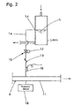
- liquid level detecting means 10 that detects if the liquid surface level L has reached a prescribed level L0 inside receiver 3.
- liquid level detecting means 10 comprises a bypass circuit 14 and a thermistor 15.
- the bypass circuit connects the prescribed level L0 in receiver 3 with the suction pipe 11 of compressor 1 and has a solenoid ON/OFF valve 12 that is actuated so as to open when the liquid level is detected to be at the prescribed level and a capillary tube 13 that acts as a pressure reducing mechanism.
- the thermistor acts as a temperature detecting means that detects the temperature of the refrigerant flowing in bypass circuit 14.
- the prescribed level L0 is the surface level of the liquid refrigerant collected in receiver 2 when the refrigerant is needed the least (i.e., when the amount of circulating refrigerant is the smallest) during air-conditioning operation.
- the prescribed level is set such that the liquid level L inside receiver 3 does not fall below a minimum level Lmin when the refrigerant is needed the most (i.e., when the amount of circulating refrigerant is the largest) during air-conditioning operation.
- Item 16 is a pressure sensor that detects the suction pressure.
- Refrigeration cycle A is equipped with a controller 18 that receives detection signals from thermistor 15 and pressure sensor 16 and sends control signals to compressor 1, expansion valve 4, outdoor fan 6, indoor fan 7 and solenoid ON/OFF valve 12.
- Controller 18 has a function whereby it acts as a refrigerant charging operation control means that executes charging of refrigeration cycle A with refrigerant while creating a refrigerant charging operation state in which liquid pipe 8 is filled with liquid refrigerant having a prescribed density and a function whereby it acts as a refrigerant charging ending means that ends the refrigerant charging executed by the refrigerant charting operation control means based on the detection signal from liquid level detecting means 10.
- the refrigerant charging operation control means controls outdoor fan 6 such that the condensation pressure at condenser 2 becomes a prescribed value (i.e., such that more liquid refrigerant than is necessary does not collect in condenser 2) and controls the opening of expansion valve 4 such that a prescribed degree of superheating can be imparted to the refrigerant at the outlet of evaporator 5 (i.e., such that the gas pipe 9 disposed between evaporator 5 and compressor 1 is filled with gaseous refrigerant).
- the refrigerant is charged through a shut-off valve (not shown in the drawings) that connects the outdoor unit X to the onsite connection piping section Z.
- the control signal from controller 18 controls outdoor fan 6 such that the condensation pressure at condenser 2 becomes a prescribed value (i.e., such that more liquid refrigerant than is necessary does not collect in condenser 2) and controls the opening of expansion valve 4 such that a prescribed degree of superheating can be imparted to the refrigerant at the outlet of evaporator 5 (i.e., such that the gas pipe 9 disposed between evaporator 5 and compressor 1 is filled with gaseous refrigerant).
- refrigeration cycle A is charged with refrigerant while a refrigerant charging operation state exists in which liquid pipe 8 is filled with liquid refrigerant having a prescribed density.
- solenoid ON/OFF valve 12 is in the opened state.
- refrigeration cycle A is charged with the required amount of refrigerant.
- the required amount of refrigerant can be charged even if the length of the connecting pipes cannot be measured onsite and the reliability of the equipment is improved.
- outdoor fan 6 is controlled such that the condensation pressure at condenser 2 becomes a prescribed value (i.e., such that more liquid refrigerant than is necessary does not collect in condenser 2) and the opening of expansion valve 4 is controlled such that a prescribed degree of superheating can be imparted to the refrigerant at the outlet of evaporator 5 (i.e., such that the gas pipe 9 disposed between evaporator 5 and compressor 1 is filled with gaseous refrigerant).
- a refrigerant charging operation state in which liquid pipe 8 is filled with liquid refrigerant having a prescribed density can be created easily.
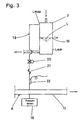
- FIG. 3 There are conventional refrigeration apparatuses that, as shown in FIG. 3, are provided with a bypass circuit 19 that connects the top edge part Lmax of receiver 3 with suction pipe 11 of compressor 1 and has a solenoid ON/OFF valve 20 and a capillary tube 21.
- This bypass circuit acts as a protection device during defrost operation, but refrigerant overcharging can be detected by providing bypass circuit 19 with a thermistor 22.
- a thermistor 22 can be used to detect if the level L of the liquid refrigerant inside receiver 3 has reached a maximum level Lmax during test running after refrigerant charging.
- a liquid surface sensor is used as the liquid level detecting means 10.
- This invention makes it possible to charge a refrigeration apparatus with the amount of refrigerant that the refrigeration apparatus requires at the time of onsite installation. As a result, the optimum refrigerant charging amount can always be obtained.
Landscapes
- Engineering & Computer Science (AREA)
- Physics & Mathematics (AREA)
- Mechanical Engineering (AREA)
- Thermal Sciences (AREA)
- General Engineering & Computer Science (AREA)
- Air Conditioning Control Device (AREA)
- Compression-Type Refrigeration Machines With Reversible Cycles (AREA)
- Other Air-Conditioning Systems (AREA)
Abstract
Description
Claims (4)
- A refrigeration apparatus equipped with
a refrigerant circuit (A) in which the following are connected together: a compressor (1) that compresses gaseous refrigerant, a heat-source-side heat exchanger (2), a receiver (3) for collecting liquid refrigerant, an expansion valve (4), a liquid pipe (8) that connects the receiver (3) and the expansion valve (4), a utilization-side heat exchanger (5), and a gas pipe (9) that connects the utilization-side heat exchanger (5) and the compressor (1); and
a liquid level detecting means (10) that detects if the surface (L) of the liquid inside the receiver (3) has reached a prescribed level (L0, Lmax). - A refrigeration apparatus as recited in claim 1, wherein the liquid level detecting means (10) comprises
a bypass circuit (14) that connects the receiver (3) and the suction side of the compressor (1) and includes an ON/OFF valve (12) and a pressure reducing mechanism (13) and a temperature detecting means (15) that detects temperature of the refrigerant flowing in the bypass circuit (14). - A refrigeration apparatus as recited in claim 1 or 2, wherein the following are further provided:a refrigerant charging operation control means that executes charging of the refrigerant circuit (A) with refrigerant while creating a refrigerant charging operation state in which the liquid pipe (8) of the refrigerant circuit (A) is filled with liquid refrigerant having a prescribed density; anda refrigerant charging ending means that ends refrigerant charging by the refrigerant charging operation control means based on the detection signal from the liquid level detecting means (10).
- A refrigeration apparatus as recited in claim 3, wherein
the heat-source-side heat exchanger (2) is an air-cooled heat exchanger that uses air supplied from an outdoor fan (6) as the heat source; and
the refrigerant charging operation control means controls the outdoor fan (6) such that the condensation pressure of the heat-source-side heat exchanger (2) (which acts as a condenser) achieves a prescribed value and controls the opening of the expansion valve (4) such that a prescribed degree of superheating can be imparted to the refrigerant at the outlet of the utilization-side heat exchanger (5) (which acts as an evaporator).
Priority Applications (1)
| Application Number | Priority Date | Filing Date | Title |
|---|---|---|---|
| EP06017966A EP1736721B1 (en) | 2001-05-22 | 2002-05-20 | Refrigeration apparatus |
Applications Claiming Priority (3)
| Application Number | Priority Date | Filing Date | Title |
|---|---|---|---|
| JP2001152091A JP2002350014A (en) | 2001-05-22 | 2001-05-22 | Refrigeration equipment |
| JP2001152091 | 2001-05-22 | ||
| PCT/JP2002/004866 WO2002103265A1 (en) | 2001-05-22 | 2002-05-20 | Refrigerator |
Related Child Applications (1)
| Application Number | Title | Priority Date | Filing Date |
|---|---|---|---|
| EP06017966A Division EP1736721B1 (en) | 2001-05-22 | 2002-05-20 | Refrigeration apparatus |
Publications (3)
| Publication Number | Publication Date |
|---|---|
| EP1389723A1 true EP1389723A1 (en) | 2004-02-18 |
| EP1389723A4 EP1389723A4 (en) | 2005-12-14 |
| EP1389723B1 EP1389723B1 (en) | 2007-03-07 |
Family
ID=18996821
Family Applications (2)
| Application Number | Title | Priority Date | Filing Date |
|---|---|---|---|
| EP02780781A Expired - Lifetime EP1389723B1 (en) | 2001-05-22 | 2002-05-20 | Refrigerator |
| EP06017966A Expired - Lifetime EP1736721B1 (en) | 2001-05-22 | 2002-05-20 | Refrigeration apparatus |
Family Applications After (1)
| Application Number | Title | Priority Date | Filing Date |
|---|---|---|---|
| EP06017966A Expired - Lifetime EP1736721B1 (en) | 2001-05-22 | 2002-05-20 | Refrigeration apparatus |
Country Status (8)
| Country | Link |
|---|---|
| US (1) | US6845626B2 (en) |
| EP (2) | EP1389723B1 (en) |
| JP (1) | JP2002350014A (en) |
| CN (1) | CN1181303C (en) |
| AU (1) | AU2002309020B2 (en) |
| DE (2) | DE60238795D1 (en) |
| ES (2) | ES2282485T3 (en) |
| WO (1) | WO2002103265A1 (en) |
Families Citing this family (38)
| Publication number | Priority date | Publication date | Assignee | Title |
|---|---|---|---|---|
| JP3719246B2 (en) * | 2003-01-10 | 2005-11-24 | ダイキン工業株式会社 | Refrigeration apparatus and refrigerant amount detection method for refrigeration apparatus |
| JP4366245B2 (en) * | 2004-05-24 | 2009-11-18 | アイシン精機株式会社 | Refrigerant supply device |
| KR20080022593A (en) * | 2004-06-11 | 2008-03-11 | 다이킨 고교 가부시키가이샤 | Air conditioner |
| JP4270197B2 (en) * | 2004-06-11 | 2009-05-27 | ダイキン工業株式会社 | Air conditioner |
| US7552596B2 (en) * | 2004-12-27 | 2009-06-30 | Carrier Corporation | Dual thermochromic liquid crystal temperature sensing for refrigerant charge indication |
| US7610765B2 (en) | 2004-12-27 | 2009-11-03 | Carrier Corporation | Refrigerant charge status indication method and device |
| US7712319B2 (en) * | 2004-12-27 | 2010-05-11 | Carrier Corporation | Refrigerant charge adequacy gauge |
| JP3963190B2 (en) | 2005-04-07 | 2007-08-22 | ダイキン工業株式会社 | Refrigerant amount determination system for air conditioner |
| JP2007127326A (en) * | 2005-11-02 | 2007-05-24 | Yanmar Co Ltd | Engine drive type heat pump comprising refrigerant filling circuit |
| JP4120676B2 (en) * | 2005-12-16 | 2008-07-16 | ダイキン工業株式会社 | Air conditioner |
| JP4562650B2 (en) * | 2005-12-16 | 2010-10-13 | ダイキン工業株式会社 | Air conditioner |
| JP4124228B2 (en) * | 2005-12-16 | 2008-07-23 | ダイキン工業株式会社 | Air conditioner |
| JP4114691B2 (en) * | 2005-12-16 | 2008-07-09 | ダイキン工業株式会社 | Air conditioner |
| JP2007163106A (en) * | 2005-12-16 | 2007-06-28 | Daikin Ind Ltd | Air conditioner |
| JP4197020B2 (en) * | 2006-08-10 | 2008-12-17 | ダイキン工業株式会社 | Refrigerant charging method in refrigeration apparatus using carbon dioxide as refrigerant |
| US7891201B1 (en) * | 2006-09-29 | 2011-02-22 | Carrier Corporation | Refrigerant vapor compression system with flash tank receiver |
| US9568226B2 (en) * | 2006-12-20 | 2017-02-14 | Carrier Corporation | Refrigerant charge indication |
| US8290722B2 (en) * | 2006-12-20 | 2012-10-16 | Carrier Corporation | Method for determining refrigerant charge |
| CN101680699B (en) * | 2006-12-28 | 2012-07-18 | 开利公司 | Free Cooling Capacity Control of Air Conditioning Systems |
| JP4225357B2 (en) * | 2007-04-13 | 2009-02-18 | ダイキン工業株式会社 | Refrigerant filling apparatus, refrigeration apparatus and refrigerant filling method |
| JP4245064B2 (en) | 2007-05-30 | 2009-03-25 | ダイキン工業株式会社 | Air conditioner |
| JP2008298335A (en) * | 2007-05-30 | 2008-12-11 | Fujitsu General Ltd | Refrigeration apparatus, additional refrigerant filling kit used for the refrigeration apparatus, and additional refrigerant charging method for refrigeration apparatus |
| NO327832B1 (en) | 2007-06-29 | 2009-10-05 | Sinvent As | Steam circuit compression dress system with closed circuit as well as method for operating the system. |
| JP2011085360A (en) * | 2009-10-19 | 2011-04-28 | Panasonic Corp | Air conditioner and installation method of the same |
| JP5582773B2 (en) | 2009-12-10 | 2014-09-03 | 三菱重工業株式会社 | Air conditioner and refrigerant amount detection method for air conditioner |
| JP5595025B2 (en) * | 2009-12-10 | 2014-09-24 | 三菱重工業株式会社 | Air conditioner and refrigerant amount detection method for air conditioner |
| JP5705453B2 (en) * | 2010-04-21 | 2015-04-22 | 三菱重工業株式会社 | Refrigerant charging method for air conditioner |
| US9146048B2 (en) * | 2010-12-29 | 2015-09-29 | Michael Shelton | Chemical state monitor for refrigeration system |
| US9759465B2 (en) | 2011-12-27 | 2017-09-12 | Carrier Corporation | Air conditioner self-charging and charge monitoring system |
| US9267717B2 (en) * | 2012-06-21 | 2016-02-23 | Trane International Inc. | System and method of charge management |
| JP5673612B2 (en) * | 2012-06-27 | 2015-02-18 | 三菱電機株式会社 | Refrigeration cycle equipment |
| JP6091506B2 (en) * | 2012-07-23 | 2017-03-08 | 三菱電機株式会社 | Refrigeration air conditioner, refrigerant leak detection device, and refrigerant leak detection method |
| JP5839084B2 (en) * | 2013-10-07 | 2016-01-06 | ダイキン工業株式会社 | Refrigeration equipment |
| CN110567210B (en) * | 2019-09-16 | 2020-11-10 | 珠海格力电器股份有限公司 | Automatic control method and device for refrigerant filling amount of water chilling unit and water chilling unit |
| CN113266929B (en) * | 2021-05-20 | 2022-10-04 | 青岛海信日立空调系统有限公司 | Multi-split air conditioner and control method thereof |
| CN113932503B (en) * | 2021-11-24 | 2023-04-07 | 宁波奥克斯电气股份有限公司 | Refrigerant charging device and control method |
| CN114877572B (en) * | 2022-05-24 | 2023-04-11 | 珠海格力电器股份有限公司 | Refrigerant recovery system and control method |
| EP4286773A1 (en) | 2022-06-01 | 2023-12-06 | Carrier Corporation | Transportation refrigeration unit and method of measuring quantity of refrigerant in the same |
Family Cites Families (30)
| Publication number | Priority date | Publication date | Assignee | Title |
|---|---|---|---|---|
| US3003332A (en) * | 1957-10-07 | 1961-10-10 | John E Watkins | Control means for refrigerating system |
| US4591839A (en) * | 1982-05-20 | 1986-05-27 | Gulf & Western Manufacturing Company | System for detecting low liquid level and probe therefor |
| US4474034A (en) | 1982-09-23 | 1984-10-02 | Avery Jr Richard J | Refrigerant accumulator and charging apparatus and method for vapor-compression refrigeration system |
| US4856288A (en) * | 1983-07-18 | 1989-08-15 | Weber Robert C | Refrigerant alert and automatic recharging device |
| JPS6073082U (en) * | 1983-10-27 | 1985-05-23 | カルソニックカンセイ株式会社 | Refrigerant overfill warning device for cooling cycle |
| JPH07103246B2 (en) | 1985-10-23 | 1995-11-08 | 鐘紡株式会社 | Electrically conductive organic polymer materials |
| JPS6296529U (en) * | 1985-12-05 | 1987-06-19 | ||
| JPS62130371U (en) * | 1986-02-08 | 1987-08-18 | ||
| US4967567A (en) * | 1987-12-10 | 1990-11-06 | Murray Corporation | System and method for diagnosing the operation of air conditioner systems |
| US5428966A (en) * | 1988-01-21 | 1995-07-04 | Alsenz; Richard H. | Refrigeration system utilizing an expansion device in the evaporator |
| CA1322858C (en) * | 1988-08-17 | 1993-10-12 | Masaki Nakao | Cooling apparatus and control method therefor |
| US5076063A (en) * | 1988-12-22 | 1991-12-31 | Sanden Corporation | Refrigerant processing and charging system |
| JP2884736B2 (en) * | 1990-08-02 | 1999-04-19 | 株式会社デンソー | Refrigerant charge detection device |
| JPH04103975A (en) * | 1990-08-22 | 1992-04-06 | Toshiba Corp | Refrigerant recovering and filling device |
| CA2053929C (en) * | 1990-11-13 | 1994-05-03 | Lowell E. Paige | Method and apparatus for recovering and purifying refrigerant |
| JPH0648288Y2 (en) * | 1990-11-29 | 1994-12-12 | サンデン株式会社 | Appropriate refrigerant filling system for automotive air conditioners |
| JPH0743193B2 (en) * | 1990-11-30 | 1995-05-15 | サンデン株式会社 | Refrigerant overfill prevention device |
| DE4124363C2 (en) * | 1991-07-23 | 1994-02-03 | Daimler Benz Ag | Procedure for monitoring the refrigerant level in a refrigeration system |
| DE4319293C2 (en) * | 1993-06-10 | 1998-08-27 | Behr Gmbh & Co | Air conditioning condenser |
| US5435145A (en) * | 1994-03-03 | 1995-07-25 | General Electric Company | Refrigerant flow rate control based on liquid level in simple vapor compression refrigeration cycles |
| JPH08121848A (en) * | 1994-10-27 | 1996-05-17 | Matsushita Refrig Co Ltd | Air conditioner |
| JPH08145510A (en) * | 1994-11-17 | 1996-06-07 | Mitsubishi Heavy Ind Ltd | Refrigerating equipment and regulating device of surplus refrigerant thereof |
| US5551248A (en) * | 1995-02-03 | 1996-09-03 | Heatcraft Inc. | Control apparatus for space cooling system |
| JP3421197B2 (en) * | 1996-07-17 | 2003-06-30 | 株式会社エヌ・ティ・ティ ファシリティーズ | Control device for air conditioner |
| JPH1163745A (en) * | 1997-08-08 | 1999-03-05 | Hitachi Ltd | Air conditioner refrigerant amount indication device and monitoring device |
| JPH1163694A (en) * | 1997-08-21 | 1999-03-05 | Zexel Corp | Refrigeration cycle |
| JP3036525B2 (en) * | 1998-08-19 | 2000-04-24 | ダイキン工業株式会社 | Air conditioner |
| US6264431B1 (en) * | 1999-05-17 | 2001-07-24 | Franklin Electric Co., Inc. | Variable-speed motor drive controller for a pump-motor assembly |
| JP2000356388A (en) * | 1999-06-11 | 2000-12-26 | Hitachi Ltd | Railcar air conditioners |
| JP2001021242A (en) * | 1999-07-06 | 2001-01-26 | Mitsubishi Electric Corp | refrigerator |
-
2001
- 2001-05-22 JP JP2001152091A patent/JP2002350014A/en active Pending
-
2002
- 2002-05-20 DE DE60238795T patent/DE60238795D1/en not_active Expired - Lifetime
- 2002-05-20 AU AU2002309020A patent/AU2002309020B2/en not_active Ceased
- 2002-05-20 EP EP02780781A patent/EP1389723B1/en not_active Expired - Lifetime
- 2002-05-20 CN CNB028017293A patent/CN1181303C/en not_active Expired - Fee Related
- 2002-05-20 DE DE60218653T patent/DE60218653T2/en not_active Expired - Lifetime
- 2002-05-20 WO PCT/JP2002/004866 patent/WO2002103265A1/en not_active Ceased
- 2002-05-20 EP EP06017966A patent/EP1736721B1/en not_active Expired - Lifetime
- 2002-05-20 ES ES02780781T patent/ES2282485T3/en not_active Expired - Lifetime
- 2002-05-20 US US10/333,055 patent/US6845626B2/en not_active Expired - Lifetime
- 2002-05-20 ES ES06017966T patent/ES2358041T3/en not_active Expired - Lifetime
Also Published As
| Publication number | Publication date |
|---|---|
| ES2282485T3 (en) | 2007-10-16 |
| ES2358041T3 (en) | 2011-05-05 |
| WO2002103265A1 (en) | 2002-12-27 |
| EP1736721A2 (en) | 2006-12-27 |
| EP1389723B1 (en) | 2007-03-07 |
| DE60238795D1 (en) | 2011-02-10 |
| EP1736721B1 (en) | 2010-12-29 |
| AU2002309020B2 (en) | 2004-07-15 |
| CN1463351A (en) | 2003-12-24 |
| EP1389723A4 (en) | 2005-12-14 |
| US20030172665A1 (en) | 2003-09-18 |
| US6845626B2 (en) | 2005-01-25 |
| JP2002350014A (en) | 2002-12-04 |
| DE60218653T2 (en) | 2007-11-22 |
| CN1181303C (en) | 2004-12-22 |
| DE60218653D1 (en) | 2007-04-19 |
| EP1736721A3 (en) | 2007-03-14 |
Similar Documents
| Publication | Publication Date | Title |
|---|---|---|
| EP1389723B1 (en) | Refrigerator | |
| JP2002350014A5 (en) | ||
| JP5011957B2 (en) | Air conditioner | |
| EP1942306B1 (en) | Air-conditioning apparatus, method of refrigerant filling in air-conditioning apparatus, method of judging state of refrigerant filling in air-conditioning apparatus, and method of refrigerant filling/piping cleaning for air-conditioning apparatus | |
| US7856836B2 (en) | Refrigerating air conditioning system | |
| AU2007244357B2 (en) | Air conditioner | |
| CN100434840C (en) | air conditioner | |
| EP2869002B1 (en) | Air conditioner and method of controlling the same | |
| JP5130910B2 (en) | Air conditioner and refrigerant quantity determination method | |
| EP1933103B1 (en) | Refrigerating/air-conditioning device | |
| US20190331374A1 (en) | Air conditioner | |
| JP2005282885A (en) | Air conditioner | |
| EP1278032B1 (en) | Method for refrigerant and oil collecting operation and refrigerant and oil collection controller | |
| CN108954501B (en) | Air conditioner | |
| US7451615B2 (en) | Refrigeration device | |
| JP5245575B2 (en) | Refrigerant amount determination method for air conditioner and air conditioner | |
| JP4278351B2 (en) | Oil level detection method and apparatus for compressor | |
| KR100743720B1 (en) | Defective Detection Method of Electronic Expansion Valve of Multi-type Air Conditioner Subcooler | |
| US7854134B2 (en) | Air conditioner | |
| JPH11201572A (en) | Multiroom air conditioner | |
| JPH06207759A (en) | Liquid gas separating device for long refrigerant pipe | |
| JP2000346467A (en) | Refrigeration cycle device | |
| JP2008111584A (en) | Air conditioner | |
| JPH03177753A (en) | Air conditioner | |
| JPH06185837A (en) | Air conditioner |
Legal Events
| Date | Code | Title | Description |
|---|---|---|---|
| PUAI | Public reference made under article 153(3) epc to a published international application that has entered the european phase |
Free format text: ORIGINAL CODE: 0009012 |
|
| 17P | Request for examination filed |
Effective date: 20030212 |
|
| AK | Designated contracting states |
Kind code of ref document: A1 Designated state(s): AT BE CH CY DE DK ES FI FR GB GR IE IT LI LU MC NL PT SE TR |
|
| A4 | Supplementary search report drawn up and despatched |
Effective date: 20051031 |
|
| GRAP | Despatch of communication of intention to grant a patent |
Free format text: ORIGINAL CODE: EPIDOSNIGR1 |
|
| GRAS | Grant fee paid |
Free format text: ORIGINAL CODE: EPIDOSNIGR3 |
|
| GRAA | (expected) grant |
Free format text: ORIGINAL CODE: 0009210 |
|
| AK | Designated contracting states |
Kind code of ref document: B1 Designated state(s): BE DE ES FR GB IT |
|
| REG | Reference to a national code |
Ref country code: GB Ref legal event code: FG4D |
|
| REF | Corresponds to: |
Ref document number: 60218653 Country of ref document: DE Date of ref document: 20070419 Kind code of ref document: P |
|
| ET | Fr: translation filed | ||
| REG | Reference to a national code |
Ref country code: ES Ref legal event code: FG2A Ref document number: 2282485 Country of ref document: ES Kind code of ref document: T3 |
|
| PLBE | No opposition filed within time limit |
Free format text: ORIGINAL CODE: 0009261 |
|
| STAA | Information on the status of an ep patent application or granted ep patent |
Free format text: STATUS: NO OPPOSITION FILED WITHIN TIME LIMIT |
|
| 26N | No opposition filed |
Effective date: 20071210 |
|
| REG | Reference to a national code |
Ref country code: FR Ref legal event code: PLFP Year of fee payment: 15 |
|
| REG | Reference to a national code |
Ref country code: FR Ref legal event code: PLFP Year of fee payment: 16 |
|
| PGFP | Annual fee paid to national office [announced via postgrant information from national office to epo] |
Ref country code: GB Payment date: 20170517 Year of fee payment: 16 Ref country code: FR Payment date: 20170413 Year of fee payment: 16 Ref country code: DE Payment date: 20170516 Year of fee payment: 16 |
|
| PGFP | Annual fee paid to national office [announced via postgrant information from national office to epo] |
Ref country code: ES Payment date: 20170605 Year of fee payment: 16 Ref country code: BE Payment date: 20170413 Year of fee payment: 16 Ref country code: IT Payment date: 20170522 Year of fee payment: 16 |
|
| REG | Reference to a national code |
Ref country code: DE Ref legal event code: R119 Ref document number: 60218653 Country of ref document: DE |
|
| GBPC | Gb: european patent ceased through non-payment of renewal fee |
Effective date: 20180520 |
|
| REG | Reference to a national code |
Ref country code: BE Ref legal event code: MM Effective date: 20180531 |
|
| PG25 | Lapsed in a contracting state [announced via postgrant information from national office to epo] |
Ref country code: GB Free format text: LAPSE BECAUSE OF NON-PAYMENT OF DUE FEES Effective date: 20180520 Ref country code: IT Free format text: LAPSE BECAUSE OF NON-PAYMENT OF DUE FEES Effective date: 20180520 Ref country code: DE Free format text: LAPSE BECAUSE OF NON-PAYMENT OF DUE FEES Effective date: 20181201 Ref country code: FR Free format text: LAPSE BECAUSE OF NON-PAYMENT OF DUE FEES Effective date: 20180531 |
|
| PG25 | Lapsed in a contracting state [announced via postgrant information from national office to epo] |
Ref country code: BE Free format text: LAPSE BECAUSE OF NON-PAYMENT OF DUE FEES Effective date: 20180531 |
|
| REG | Reference to a national code |
Ref country code: ES Ref legal event code: FD2A Effective date: 20190913 |
|
| PG25 | Lapsed in a contracting state [announced via postgrant information from national office to epo] |
Ref country code: ES Free format text: LAPSE BECAUSE OF NON-PAYMENT OF DUE FEES Effective date: 20180521 |