EP1389648A1 - Concrete floor slab - Google Patents
Concrete floor slab Download PDFInfo
- Publication number
- EP1389648A1 EP1389648A1 EP03255115A EP03255115A EP1389648A1 EP 1389648 A1 EP1389648 A1 EP 1389648A1 EP 03255115 A EP03255115 A EP 03255115A EP 03255115 A EP03255115 A EP 03255115A EP 1389648 A1 EP1389648 A1 EP 1389648A1
- Authority
- EP
- European Patent Office
- Prior art keywords
- divider plate
- height
- leg
- dowels
- edge
- Prior art date
- Legal status (The legal status is an assumption and is not a legal conclusion. Google has not performed a legal analysis and makes no representation as to the accuracy of the status listed.)
- Granted
Links
- 229910000831 Steel Inorganic materials 0.000 claims description 4
- 239000010959 steel Substances 0.000 claims description 4
- 239000004033 plastic Substances 0.000 claims description 3
- 229920003023 plastic Polymers 0.000 claims description 3
- 239000002184 metal Substances 0.000 claims description 2
- 230000001419 dependent effect Effects 0.000 claims 1
- 238000009415 formwork Methods 0.000 description 6
- 238000000034 method Methods 0.000 description 5
- 238000005266 casting Methods 0.000 description 4
- 239000004677 Nylon Substances 0.000 description 2
- 229920001778 nylon Polymers 0.000 description 2
- 230000015556 catabolic process Effects 0.000 description 1
- 229910003460 diamond Inorganic materials 0.000 description 1
- 239000010432 diamond Substances 0.000 description 1
- 230000000694 effects Effects 0.000 description 1
- 238000003780 insertion Methods 0.000 description 1
- 230000037431 insertion Effects 0.000 description 1
- 239000000463 material Substances 0.000 description 1
- 238000012856 packing Methods 0.000 description 1
- 230000000717 retained effect Effects 0.000 description 1
- 238000000926 separation method Methods 0.000 description 1
- 238000010008 shearing Methods 0.000 description 1
- 238000005728 strengthening Methods 0.000 description 1
Images


Classifications
-
- E—FIXED CONSTRUCTIONS
- E01—CONSTRUCTION OF ROADS, RAILWAYS, OR BRIDGES
- E01C—CONSTRUCTION OF, OR SURFACES FOR, ROADS, SPORTS GROUNDS, OR THE LIKE; MACHINES OR AUXILIARY TOOLS FOR CONSTRUCTION OR REPAIR
- E01C11/00—Details of pavings
- E01C11/02—Arrangement or construction of joints; Methods of making joints; Packing for joints
- E01C11/04—Arrangement or construction of joints; Methods of making joints; Packing for joints for cement concrete paving
- E01C11/08—Packing of metal
-
- E—FIXED CONSTRUCTIONS
- E01—CONSTRUCTION OF ROADS, RAILWAYS, OR BRIDGES
- E01C—CONSTRUCTION OF, OR SURFACES FOR, ROADS, SPORTS GROUNDS, OR THE LIKE; MACHINES OR AUXILIARY TOOLS FOR CONSTRUCTION OR REPAIR
- E01C11/00—Details of pavings
- E01C11/02—Arrangement or construction of joints; Methods of making joints; Packing for joints
- E01C11/04—Arrangement or construction of joints; Methods of making joints; Packing for joints for cement concrete paving
- E01C11/14—Dowel assembly ; Design or construction of reinforcements in the area of joints
Definitions
- This invention relates to the forming of concrete floor slabs, particularly the forming of the edges of the slabs, and to providing improved means for load transfer between adjacent slabs.
- the invention provides apparatus for forming the edge of a concrete floor slab, the apparatus comprising a divider plate formed with a plurality of apertures, dowels for engaging through the apertures and sleeves for applying to the dowels, in which the divider plate is provided with means, in use, to adjust the height thereof above the ground.
- the divider plate is preferably formed from metal and is intended to be left in place between slabs cast on each side thereof.
- the divider plate may be supported above ground level on longitudinally spaced apart feet, the feet being operatively connected to the height-adjustment means.
- the apertures formed in the divider plate may be any shape and size in order to receive the dowels, which may be round, square, or formed as flat plates, for example rectangular or trapezoidal plates.
- the dowels may comprise means for receiving and securing the height-adjustment means, or the height-adjustment means may be attached direct to the divider plate.
- the sleeves for applying to the dowels will correspond internally with the shape of the dowels used, in order to provide relative two-way horizontal sliding movement and a tight fit vertically.
- the sleeves are preferably formed from a plastics material to reduce the coefficient of friction between the dowels and sleeves
- the sleeves may be formed with lug or ridge members which allows them to be retained in place within the slabs cast.
- the means for adjusting the height of the divider plate above ground level may comprise a leg and means for attachment of the leg to the divider plate at a selected height.
- the leg may be attached direct to the divider plate by a lock means which is passed through a vertical slot formed either in the leg or the plate to provide for height adjustment.
- the leg may be screw threaded and can either be threaded or passed through the dowel or through a collar attached to the dowel with means for altering the position of the dowel along the length of the leg.
- such means may comprise a slot or socket to receive a suitable driver to rotate the leg.
- such means may comprise adjustment nuts and suitable washers. In either case, the effect is to move the dowel vertically along the leg in order to adjust the height of the apparatus through the engagement of the dowel with the divider plate.
- the apparatus may further comprise edge rails which are preferably supportable by the divider plate to provide protection to the arris of the cast slabs.
- the edge rails may further comprise anchor means which become embedded in the concrete during curing and which fix the edge rails in position.
- the edge rails of adjoining slabs are preferably attached together with yieldable fixings wherein, as shrinking occurs during the curing process and the edge rails of adjacent slabs are drawn apart, the fixings yield to allow for the movement.
- the yieldable fixing may comprise low-tensile bolts, for example formed from nylon, the threads of which will become stripped under shrinkage forces.
- the bolts may be steel to hold the edge rails firmly together until after a first slab has been cast on one side of the apparatus, the nuts then being removed from the other side before the second slab is cast.
- the fixings for the edge rails are preferably located in holes formed through the rails, the fixings carrying a longitudinally-split resilient steel or plastics sleeve to take up any free space between the fixings or the shanks thereof and the holes, to ensure that adjacent rails are accurately placed in position.
- the height-adjustment means is attached to the edge rails or to the anchor means thereof.
- Apparatus according to the invention can be used to form prefabricated four-way intersections, three-way "T" intersections, corner units and loading dock units.
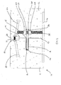
- the apparatus shown generally at 10 is embedded in concrete slabs 11 and 12.
- the apparatus is pre-assembled and is put in place before the concrete slabs are cast.
- a divider plate 13 is disposed at right angles across feet 14 which are positioned on the ground.
- the divider plate 13 has apertures 15 which receive trapezoidal dowel plates 16, the median length of the dowel plates corresponding with the length of the apertures so that approximately half of each dowel plate protrudes through its respective aperture, the other half (having the longer edge) remaining protruding from the insertion side of the divider plate.
- a sleeve 17 formed with external ridges 18 is applied over the portion of the dowel plate which protrudes from the aperture and has the shorter edge.
- the upper end region of the divider plate 13 is provided with a seating 19 which supports an edge rail 20 for the slab 12 which is itself attached to an edge rail 21 for the adjacent slab 11 by low-tensile bolts 22.
- Each edge rail is formed with anchors 23, 24 which become embedded into the concrete during the casting process.
- the apparatus is supported on height adjustable legs 25 which are attached to respective feet 14 and inserted through holes 26 in the dowel plates 16 and secured therein by nuts 27, 28 and washers 29, 30.
- the height of the divider plate can be adjusted by the movement of the dowel plate 16 up or down the leg 25, by manipulation of the nuts 27, 28 until the divider plate is level and with the upper edges of the rails 20, 21 at the desired height. Further apparatus can then be attached at the ends and height-adjusted; preferably, the edge rails are slightly longitudinally offset to provide a lap joint where adjacent divider plates meet end to end.
- the slabs are cast and left to cure. During the curing process the slabs shrink and cause the edges of the slabs to become separated from one another.
- FIG. 3 shows slabs 11, 12 which have become separated due to shrinkage leaving a gap 31.
- the bolt 22 has sheared to allow the separation of the adjacent slabs and anchors 23, 24 which are embedded in the set concrete, secure the respective edge rails 21, 20 to the arrises of slabs 11, 12 to protect them.
- the dowel plate 16, which is attached to leg 25, is movable within the sleeve 17 in two horizontal directions but not vertically.
- a divider plate 41 formed with an upturned lower edge 42 for strengthening purposes, is supported on detachable legs 43 attached to ground-engaging feet 44.
- the divider plate 41 carries a series of vertical slots 45, the legs 43 and feet 44 being attached to selected slots with bolts 46 and nuts 47, shown as wing-nuts 48 in Figure 5.
- the height of the divider plate relative to the ground may be adjusted by virtue of relative movement between the slot 45 and the bolts 46.
- trapezoidal dowel plates 49 are passed through horizontal slots formed in the divider plate and sleeves 50 are applied from the other side of the divider plate, over the protruding portion of the dowel plates.
- the dowel plates could be other shapes, for example rectangular or square, in the latter case being inserted through the divider plate such that opposite corners extend from the divider plate as triangular forms, as in Figure 5.
- the upper edge of the divider plate carries edge rails 51, 52, secured together by bolts 53 and nuts 54.
- the bolts formed from nylon, carry a longitudinally-split sleeving 55 around the shank thereof to ensure that, with the rails 51 and 52 secured together, there is no possibility of relative movement between them which will result in the upper edges of the rails becoming misaligned with each other.
- Anchor pins 56, 57 are welded to the respective rails 51, 52 at intervals.
- edge rails 51, 52 could be longitudinally offset so that their ends, instead of being flush as shown in Figure 4, are staggered so that, when placed in end-to-end relationship with another divider plate and edge rails, the edge rails form a lap joint.
- sets 71 to 74 of apparatus intersecting orthogonally at a prefabricated joint 75 between four slabs.
- the four limbs of the joint 75 which are joined to respective divider plates with the edge rails forming lap joints 76, 77, 78 , 79 can move to allow for shrinkage when each slab is cast.
- the respective sets have different arrangements of dowel plates and height-adjustment means: sets 71 and 74 have trapezoidal dowel plates and sleeves 80, 81 and sets 72 and 73 have diamond-shaped dowel plates and sleeves 82, 83.
- Height-adjustment of set 71 is provided by means of rods 84 welded to concrete anchor pins 85 and supported by legs 86 welded at the appropriate distance to achieve the desired height.
- Set 73 has screw-threaded legs 87 engaged through holes in the plates 82 by nuts 88 and washers 89.
- Set 74 has a separate height-adjustment jack arrangement consisting of a base 90 and leg 91 slidingly carrying an arm 92 temporarily attached to the edge rail and movable up or down by turning screw-threaded rod 93 via nut 94, captive nut 95 being welded to the arm 92 via slider 96. The jack is used on the side remote from the first cast slab and removed before the second slab is cast.
Landscapes
- Engineering & Computer Science (AREA)
- Architecture (AREA)
- Civil Engineering (AREA)
- Structural Engineering (AREA)
- On-Site Construction Work That Accompanies The Preparation And Application Of Concrete (AREA)
- Forms Removed On Construction Sites Or Auxiliary Members Thereof (AREA)
- Building Environments (AREA)
- Road Paving Structures (AREA)
- Bridges Or Land Bridges (AREA)
- Laminated Bodies (AREA)
- Road Repair (AREA)
Abstract
Description
- This invention relates to the forming of concrete floor slabs, particularly the forming of the edges of the slabs, and to providing improved means for load transfer between adjacent slabs.
- It is well known that concrete floor slabs are cast in place inside a formwork commonly constructed from timber. The formwork provides an edge and defines a space in which to cast the concrete; it does not, however, provide support or protection during the casting or curing process or throughout the lifetime of the slab.
- When casting slabs using the known formwork it is difficult to arrange the formwork such that the upper edge thereof coincides with the intended level of the upper surface of the slab. Packing pieces such as wedges are used in order to adjust the height of the formwork in which to cast the slabs.
- Once cast, concrete slabs are prone to shrinkage during curing which causes the edges of the slabs to separate and expose the upper edge or arris of each individual slab to damage from loads, such as from lorries, passing across the joint.
- Individual slabs often support heavy loads passing from one slab to another and therefore require a method of load transfer between adjacent slabs in order to prevent breakdown of the joint between adjacent slabs caused by stresses induced by such loads. Typically round or square steel rods, commonly known as dowels, are embedded in the concrete to extend at 90 degrees across the formed joint and connect the slabs together in order to transfer a load from one slab, across the joint, to the adjacent slab. However, when the slab shrinks during curing, the dowels embedded in the concrete themselves create stresses in the slabs due to differential shrinkage between adjacent bays of concrete, this becoming a further cause of cracks in the slabs particularly at comers. In any event, a load transferred by a dowel results in concentrated zones of stress immediately above the dowel, with consequential risk of edge cracks occurring. WO99/31329 proposes, as a solution to this problem, the use of plate dowels and sleeves, called "blockout sheaths", to spread the loads more effectively and to provide for relative movement between the dowels and the concrete. However, the problems of formwork height and edge damage to the cured slabs remain.
- It is therefore an object of this invention to provide height-adjustable apparatus for forming the edges of concrete floor slabs, to provide means for load transfer between adjacent slabs and preferably to protect the arris of the slab after casting of the concrete.
- In one aspect the invention provides apparatus for forming the edge of a concrete floor slab, the apparatus comprising a divider plate formed with a plurality of apertures, dowels for engaging through the apertures and sleeves for applying to the dowels, in which the divider plate is provided with means, in use, to adjust the height thereof above the ground.
- The divider plate is preferably formed from metal and is intended to be left in place between slabs cast on each side thereof. The divider plate may be supported above ground level on longitudinally spaced apart feet, the feet being operatively connected to the height-adjustment means.
- The apertures formed in the divider plate may be any shape and size in order to receive the dowels, which may be round, square, or formed as flat plates, for example rectangular or trapezoidal plates. The dowels may comprise means for receiving and securing the height-adjustment means, or the height-adjustment means may be attached direct to the divider plate. The sleeves for applying to the dowels will correspond internally with the shape of the dowels used, in order to provide relative two-way horizontal sliding movement and a tight fit vertically. The sleeves are preferably formed from a plastics material to reduce the coefficient of friction between the dowels and sleeves The sleeves may be formed with lug or ridge members which allows them to be retained in place within the slabs cast.
- The means for adjusting the height of the divider plate above ground level may comprise a leg and means for attachment of the leg to the divider plate at a selected height. The leg may be attached direct to the divider plate by a lock means which is passed through a vertical slot formed either in the leg or the plate to provide for height adjustment. However, in another embodiment, the leg may be screw threaded and can either be threaded or passed through the dowel or through a collar attached to the dowel with means for altering the position of the dowel along the length of the leg. Where the leg is threadedly engaged, such means may comprise a slot or socket to receive a suitable driver to rotate the leg. Where the leg is passed through, such means may comprise adjustment nuts and suitable washers. In either case, the effect is to move the dowel vertically along the leg in order to adjust the height of the apparatus through the engagement of the dowel with the divider plate.
- The apparatus may further comprise edge rails which are preferably supportable by the divider plate to provide protection to the arris of the cast slabs. The edge rails may further comprise anchor means which become embedded in the concrete during curing and which fix the edge rails in position. The edge rails of adjoining slabs are preferably attached together with yieldable fixings wherein, as shrinking occurs during the curing process and the edge rails of adjacent slabs are drawn apart, the fixings yield to allow for the movement. The yieldable fixing may comprise low-tensile bolts, for example formed from nylon, the threads of which will become stripped under shrinkage forces. However, at least some of the bolts may be steel to hold the edge rails firmly together until after a first slab has been cast on one side of the apparatus, the nuts then being removed from the other side before the second slab is cast. The fixings for the edge rails are preferably located in holes formed through the rails, the fixings carrying a longitudinally-split resilient steel or plastics sleeve to take up any free space between the fixings or the shanks thereof and the holes, to ensure that adjacent rails are accurately placed in position. Optionally, the height-adjustment means is attached to the edge rails or to the anchor means thereof.
- Apparatus according to the invention can be used to form prefabricated four-way intersections, three-way "T" intersections, corner units and loading dock units.
- Embodiments of the invention will now be described by way of example with reference to the accompanying drawings, in which
- Figure 1 is a cross section of one form of apparatus according to the invention forming a joint between two adjacent concrete slabs;
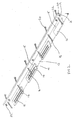
- Figure 2 is a perspective view of parts of the apparatus of Figure 1;
- Figure 3 is a cross section of the apparatus in Figure 1 once the slabs have cured, shrinkage has taken place and the joint opened;
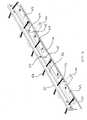
- Figure 4 is a perspective view of an alternative form of apparatus including trapezoidal plate dowels according to the invention;
- Figure 5 is a perspective view of the apparatus shown in Figure 4 including diamond dowels;
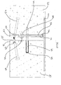
- Figure 6 is a cross section showing the apparatus of Figure 4 in place between two cured slabs of concrete; and
- Figure 7 shows a general perspective view of apparatus according to the invention when arranged to form a four-way intersection.
-
- With reference to Figures 1 and 2, the apparatus shown generally at 10 is embedded in
concrete slabs 11 and 12. The apparatus is pre-assembled and is put in place before the concrete slabs are cast. Adivider plate 13 is disposed at right angles across feet 14 which are positioned on the ground. Thedivider plate 13 hasapertures 15 which receivetrapezoidal dowel plates 16, the median length of the dowel plates corresponding with the length of the apertures so that approximately half of each dowel plate protrudes through its respective aperture, the other half (having the longer edge) remaining protruding from the insertion side of the divider plate. Once thedowel plate 16 has been inserted through the aperture of thedivider plate 13, asleeve 17 formed withexternal ridges 18 is applied over the portion of the dowel plate which protrudes from the aperture and has the shorter edge. The upper end region of thedivider plate 13 is provided with a seating 19 which supports anedge rail 20 for theslab 12 which is itself attached to anedge rail 21 for the adjacent slab 11 by low-tensile bolts 22. Each edge rail is formed withanchors adjustable legs 25 which are attached to respective feet 14 and inserted throughholes 26 in thedowel plates 16 and secured therein bynuts washers 29, 30. In use, the height of the divider plate can be adjusted by the movement of thedowel plate 16 up or down theleg 25, by manipulation of thenuts rails - Once the pre-assembled apparatus has been put in place the slabs are cast and left to cure. During the curing process the slabs shrink and cause the edges of the slabs to become separated from one another.
- Figure 3 shows
slabs 11, 12 which have become separated due to shrinkage leaving agap 31. Thebolt 22 has sheared to allow the separation of the adjacent slabs andanchors respective edge rails slabs 11, 12 to protect them. In addition, to reduce the stress on the individual slabs caused by shrinkage, thedowel plate 16, which is attached toleg 25, is movable within thesleeve 17 in two horizontal directions but not vertically. - With reference to Figure 4, Figure 5 and Figure 6, a
divider plate 41, formed with an upturnedlower edge 42 for strengthening purposes, is supported ondetachable legs 43 attached to ground-engaging feet 44. Thedivider plate 41 carries a series ofvertical slots 45, thelegs 43 andfeet 44 being attached to selected slots withbolts 46 andnuts 47, shown as wing-nuts 48 in Figure 5. The height of the divider plate relative to the ground may be adjusted by virtue of relative movement between theslot 45 and thebolts 46. - As with the apparatus shown in Figures 1 to 3,
trapezoidal dowel plates 49, as in Figure 4, are passed through horizontal slots formed in the divider plate and sleeves 50 are applied from the other side of the divider plate, over the protruding portion of the dowel plates. Optionally, the dowel plates could be other shapes, for example rectangular or square, in the latter case being inserted through the divider plate such that opposite corners extend from the divider plate as triangular forms, as in Figure 5. - The upper edge of the divider plate carries
edge rails bolts 53 andnuts 54. The bolts, formed from nylon, carry a longitudinally-split sleeving 55 around the shank thereof to ensure that, with therails Anchor pins respective rails - With particular reference to Figure 5,
concrete slabs divider plate 41 and the concrete has cured. In the process, the concrete has shrunk and the edge rails 51, 52, secured to the respective slabs by the anchor pins 56, 57, have been drawn apart by shearing of the threads of thebolt 53 in thenut 54. Thedowels 49 have withdrawn slightly from the sleeves 50 as the slabs move apart. As with the apparatus shown in Figures 1 to 3, the edge rails 51, 52 could be longitudinally offset so that their ends, instead of being flush as shown in Figure 4, are staggered so that, when placed in end-to-end relationship with another divider plate and edge rails, the edge rails form a lap joint. - With reference to Figure 7, four
sets 71 to 74 of apparatus are shown intersecting orthogonally at a prefabricated joint 75 between four slabs. The four limbs of the joint 75 which are joined to respective divider plates with the edge rails forminglap joints sleeves 80, 81 and sets 72 and 73 have diamond-shaped dowel plates andsleeves 82, 83. Height-adjustment ofset 71 is provided by means ofrods 84 welded to concrete anchor pins 85 and supported bylegs 86 welded at the appropriate distance to achieve the desired height.Set 73 has screw-threadedlegs 87 engaged through holes in the plates 82 bynuts 88 andwashers 89.Set 74 has a separate height-adjustment jack arrangement consisting of a base 90 and leg 91 slidingly carrying anarm 92 temporarily attached to the edge rail and movable up or down by turning screw-threadedrod 93 vianut 94,captive nut 95 being welded to thearm 92 viaslider 96. The jack is used on the side remote from the first cast slab and removed before the second slab is cast.
Claims (17)
- Apparatus for forming the edge of a concrete floor slab, the apparatus comprising a divider plate formed with a plurality of apertures, dowels for engaging through the apertures and sleeves for applying to the dowels, in which the divider plate is provided with means, in use, to adjust the height thereof above the ground.
- Apparatus according to claim 1, in which the divider plate is formed from metal
- Apparatus according to claim 1 or claim 2 in which the divider plate is supported above ground level on longitudinally spaced apart feet, the feet being operatively connected to the height-adjustment means.
- Apparatus according to any preceding claim, in which the dowels are formed as flat plates.
- Apparatus according to any preceding claim, in which the dowels comprise means for receiving and securing the height-adjustment means.
- Apparatus according to any of claims 1 to 4, in which the height-adjustment means is attached direct to the divider plate.
- Apparatus according to any preceding claim, in which the means for adjusting the height of the divider plate comprises a leg and means for attachment of the leg to the divider plate at a selected height.
- Apparatus according to claim 7, in which the leg is screw threaded.
- Apparatus according to claim 8, in which the leg is passed through an aperture formed in the dowel and is provided with dowel-engaging adjustment nuts.
- Apparatus according to claim 7, in which the leg is attached direct to the divider plate by a lock means in operative engagement with an adjustment slot.
- Apparatus according to any preceding claim further comprising edge rails supportable by the divider plate.
- Apparatus according to claim 11, in which the edge rails further comprise anchor means for embedding in the concrete.
- Apparatus according to claim 11 or claim 12, in which the edge rails of adjoining slabs are attached together with a yieldable fixing.
- Apparatus according to claim 13, in which the yieldable fixing comprises low-tensile bolts.
- Apparatus according to claim 13 or claim 14, in which the fixings are located in holes formed through the rails, the fixings carrying a longitudinally-split resilient steel or plastics sleeve.
- Apparatus according to any of claims 11 to 15 as dependent on any of claims 1 to 4, in which the height-adjustment means is attached to the edge rails or to the anchor means thereof.
- Apparatus according to any preceding claim when prefabricated to form a four-way, three-way or corner intersection.
Priority Applications (5)
| Application Number | Priority Date | Filing Date | Title |
|---|---|---|---|
| EP07075054A EP1783277A1 (en) | 2002-08-16 | 2003-08-18 | Concrete floor slab |
| EP05013230A EP1584746A3 (en) | 2002-08-16 | 2003-08-18 | Concrete floor slab |
| EP08160562A EP1985759B1 (en) | 2002-08-16 | 2003-08-18 | Concrete Floor Slab |
| SI200330763T SI1389648T1 (en) | 2002-08-16 | 2003-08-18 | Concrete floor slab |
| EP07075698A EP1867783A3 (en) | 2002-08-16 | 2003-08-18 | Concrete floor slab |
Applications Claiming Priority (4)
| Application Number | Priority Date | Filing Date | Title |
|---|---|---|---|
| GB0219087A GB0219087D0 (en) | 2002-08-16 | 2002-08-16 | Permaban stripjoint |
| GB0219087 | 2002-08-16 | ||
| GB0219121 | 2002-08-16 | ||
| GB0219121A GB0219121D0 (en) | 2002-08-16 | 2002-08-16 | Permaban alpha joint |
Related Child Applications (3)
| Application Number | Title | Priority Date | Filing Date |
|---|---|---|---|
| EP07075054A Division EP1783277A1 (en) | 2002-08-16 | 2003-08-18 | Concrete floor slab |
| EP05013230A Division EP1584746A3 (en) | 2002-08-16 | 2003-08-18 | Concrete floor slab |
| EP08160562A Division EP1985759B1 (en) | 2002-08-16 | 2003-08-18 | Concrete Floor Slab |
Publications (2)
| Publication Number | Publication Date |
|---|---|
| EP1389648A1 true EP1389648A1 (en) | 2004-02-18 |
| EP1389648B1 EP1389648B1 (en) | 2007-01-24 |
Family
ID=30772051
Family Applications (5)
| Application Number | Title | Priority Date | Filing Date |
|---|---|---|---|
| EP07075054A Withdrawn EP1783277A1 (en) | 2002-08-16 | 2003-08-18 | Concrete floor slab |
| EP03255115A Expired - Lifetime EP1389648B1 (en) | 2002-08-16 | 2003-08-18 | Concrete floor slab |
| EP07075698A Withdrawn EP1867783A3 (en) | 2002-08-16 | 2003-08-18 | Concrete floor slab |
| EP05013230A Withdrawn EP1584746A3 (en) | 2002-08-16 | 2003-08-18 | Concrete floor slab |
| EP08160562A Revoked EP1985759B1 (en) | 2002-08-16 | 2003-08-18 | Concrete Floor Slab |
Family Applications Before (1)
| Application Number | Title | Priority Date | Filing Date |
|---|---|---|---|
| EP07075054A Withdrawn EP1783277A1 (en) | 2002-08-16 | 2003-08-18 | Concrete floor slab |
Family Applications After (3)
| Application Number | Title | Priority Date | Filing Date |
|---|---|---|---|
| EP07075698A Withdrawn EP1867783A3 (en) | 2002-08-16 | 2003-08-18 | Concrete floor slab |
| EP05013230A Withdrawn EP1584746A3 (en) | 2002-08-16 | 2003-08-18 | Concrete floor slab |
| EP08160562A Revoked EP1985759B1 (en) | 2002-08-16 | 2003-08-18 | Concrete Floor Slab |
Country Status (7)
| Country | Link |
|---|---|
| EP (5) | EP1783277A1 (en) |
| AT (2) | ATE489505T1 (en) |
| DE (2) | DE60311366T2 (en) |
| DK (1) | DK1389648T3 (en) |
| ES (1) | ES2281606T3 (en) |
| PT (1) | PT1389648E (en) |
| SI (1) | SI1389648T1 (en) |
Cited By (41)
| Publication number | Priority date | Publication date | Assignee | Title |
|---|---|---|---|---|
| WO2005111307A1 (en) | 2004-05-19 | 2005-11-24 | Coredis S.A. | Lightweight metal joint for concrete surfaces |
| WO2006016133A1 (en) * | 2004-08-10 | 2006-02-16 | Seamus Michael Devlin | Slab joint |
| BE1016147A3 (en) * | 2004-08-04 | 2006-04-04 | Coredis S A | Concrete slab metallic joint, has female part, placed in slab, with longitudinal flat bar and mortises that cooperate with tenons of male part, placed in another slab, having continuous flat bar, where bars form upper arris between slabs |
| WO2005111332A3 (en) * | 2004-05-14 | 2006-04-20 | David Peter Samson | A load plate and method of casting adjacent slabs of concrete |
| EP1801311A1 (en) * | 2005-12-21 | 2007-06-27 | MGSI- Acessorios Para Industrias, LDA | Slab formwork system |
| WO2007071995A1 (en) * | 2005-12-21 | 2007-06-28 | Permaban Limited | Screed rail |
| US7314333B2 (en) | 2003-08-13 | 2008-01-01 | Shaw & Sons, Inc. | Plate concrete dowel system |
| US7338230B2 (en) | 2003-08-13 | 2008-03-04 | Shaw & Sons, Inc. | Plate concrete dowel system |
| US7381008B2 (en) | 2003-08-13 | 2008-06-03 | Shaw Lee A | Disk plate concrete dowel system |
| EP2060701A1 (en) | 2007-11-16 | 2009-05-20 | Plakabeton S.A. | Device for applying expansion joints |
| US7604432B2 (en) | 2003-08-13 | 2009-10-20 | Shaw & Sons, Inc. | Plate concrete dowel system |
| WO2009153604A1 (en) * | 2008-06-20 | 2009-12-23 | Permaban Limited | Screed rail apparatus |
| EP2216442A1 (en) | 2009-02-06 | 2010-08-11 | Plakabeton S.A. | Device for fitting an expansion joint, in particular an expansion joint between concrete slabs |
| GB2475289A (en) * | 2009-11-12 | 2011-05-18 | Peikko Group Oy | Apparatus for adjusting the height of a floor joint system |
| GB2476055A (en) * | 2009-12-08 | 2011-06-15 | Peikko Group Oy | Frangible connector for clamping two slotted plates together |
| FR2964131A1 (en) * | 2010-08-30 | 2012-03-02 | Sifloor | Formwork height adjusting device for concrete slabs used to cover floor, has plate and backplate including holes and openings to receive bolts such that plate is adjusted in height and blocked in position at determined height based on needs |
| US20120102862A1 (en) * | 2010-10-28 | 2012-05-03 | Underwood Companies Holdings Pty Ltd. | Metal edging for concrete slabs |
| US8302359B2 (en) | 2001-08-01 | 2012-11-06 | Russell Boxall | System of protecting the edges and construction joints of cast in place concrete slabs |
| US8347574B2 (en) | 2009-10-21 | 2013-01-08 | Plakabeton S.A. | Joint elements for slabs |
| WO2013038123A1 (en) * | 2011-09-14 | 2013-03-21 | Permaban Limited | Movement joint |
| EP2594693A1 (en) | 2011-11-17 | 2013-05-22 | Sifloor | Device for adjusting the height of a formwork for concrete slabs |
| US8516761B2 (en) | 2008-01-21 | 2013-08-27 | Peikko Group Oy | Expansion joint system of concrete slab arrangement |
| US8539726B2 (en) | 2008-01-21 | 2013-09-24 | Peikko Group Oy | Expansion joint system of concrete slab arrangement |
| AU2010236065B2 (en) * | 2009-10-28 | 2014-02-20 | Illinois Tool Works Inc. | Edging For Concrete Slabs |
| GB2507071A (en) * | 2012-10-17 | 2014-04-23 | Shaun Spurrell | Apparatus for forming the edge of a concrete floor slab with an adjustable extension |
| EP2993267A1 (en) | 2014-09-05 | 2016-03-09 | Sifloor | Formwork system comprising an improved expansion joint |
| GB2530344A (en) * | 2014-09-22 | 2016-03-23 | Shaun Anthony Spurrell | Apparatus |
| US9617694B2 (en) | 2014-01-15 | 2017-04-11 | Shaw & Sons, Inc. | Concrete dowel system |
| IT201600095976A1 (en) * | 2016-09-23 | 2018-03-23 | Nordwind S R L | METHOD FOR THE CONSOLIDATION OF ROAD FLOORING IN CONCRETE AND METHODS FOR RESTORING ROAD FLOORING IN CONCRETE THAT USE THE CONSOLIDATION METHOD |
| US10077551B2 (en) | 2015-10-05 | 2018-09-18 | Illinois Tool Works Inc. | Joint edge assembly and method for forming joint in offset position |
| US10119281B2 (en) | 2016-05-09 | 2018-11-06 | Illinois Tool Works Inc. | Joint edge assembly and formwork for forming a joint, and method for forming a joint |
| EP2930269B1 (en) | 2006-06-12 | 2019-02-27 | Hengelhoef Concrete Joints NV | Structural joint |
| WO2019074628A1 (en) * | 2017-10-13 | 2019-04-18 | Illinois Tool Works Inc. | Edge protection system with intersection module |
| US10428518B2 (en) | 2017-01-16 | 2019-10-01 | Midwest Concrete & Masonry Supply, Inc. | Floor dowel sleeve for concrete slab seams |
| US10858825B2 (en) | 2015-10-05 | 2020-12-08 | Shaw & Sons, Inc. | Concrete dowel placement system and method of making the same |
| US11136756B2 (en) * | 2017-10-13 | 2021-10-05 | Illinois Tool Works Inc. | Edge protection system having dowel plate |
| US11280087B2 (en) | 2017-10-13 | 2022-03-22 | Illinois Tool Works Inc. | Edge protection system with intersection module |
| US11623380B2 (en) | 2015-10-05 | 2023-04-11 | Shaw & Sons, Inc. | Concrete dowel placement system and method of making the same |
| WO2023152425A1 (en) | 2022-02-08 | 2023-08-17 | Peikko Group Oy | Method for providing a movement joint in a concrete floor and movement floor joint apparatus |
| PL131556U1 (en) * | 2023-07-13 | 2025-01-20 | Świderski Adam Aspuro | Expansion strip assembly |
| US12291861B2 (en) | 2021-08-25 | 2025-05-06 | Illinois Tool Works Inc. | Connection system |
Families Citing this family (10)
| Publication number | Priority date | Publication date | Assignee | Title |
|---|---|---|---|---|
| US20070134063A1 (en) | 2005-12-14 | 2007-06-14 | Shaw And Sons, Inc. | Dowel device with closed end speed cover |
| WO2008136690A1 (en) * | 2007-05-04 | 2008-11-13 | Pcln Holdings Limited | Armour joint assembly support apparatus |
| DE102009054028B4 (en) * | 2009-11-19 | 2013-01-31 | Sabine Obelode | joint profile |
| GB201120321D0 (en) | 2011-11-24 | 2012-01-04 | Spurrrell Shaun | Apparatus |
| AR090164A1 (en) | 2012-02-27 | 2014-10-22 | Hengelhoef Concrete Joints Mfg Nv | EXPANSION MEETING |
| GB2500626A (en) * | 2012-03-27 | 2013-10-02 | Shaun Spurrell | Zig zag concrete floor joint apparatus |
| US9340969B1 (en) | 2014-11-13 | 2016-05-17 | Shaw & Sons, Inc. | Crush zone dowel tube |
| WO2017072409A1 (en) | 2015-10-27 | 2017-05-04 | Peikko Group Oy | Apparatus and method for joining two floor slabs made of mouldable material |
| US10662642B2 (en) | 2018-04-03 | 2020-05-26 | Midwest Concrete & Masonry Supply, Inc. | Floor dowel sleeve with integral spacing chambers |
| US11578491B2 (en) | 2020-02-07 | 2023-02-14 | Shaw Craftsmen Concrete, Llc | Topping slab installation methodology |
Citations (3)
| Publication number | Priority date | Publication date | Assignee | Title |
|---|---|---|---|---|
| EP0410079A1 (en) * | 1989-07-27 | 1991-01-30 | Claude Meyers | Connecting casing for linked concrete slabs |
| WO1999031329A1 (en) | 1997-11-26 | 1999-06-24 | Permaban North America, Inc. | System for transferring loads between cast-in-place slabs |
| DE20110547U1 (en) * | 2001-06-26 | 2001-10-04 | K.-H. Wiegrink GmbH, 46395 Bocholt | Formwork element for floors |
Family Cites Families (10)
| Publication number | Priority date | Publication date | Assignee | Title |
|---|---|---|---|---|
| US2121573A (en) * | 1936-11-21 | 1938-06-21 | Translode Joint Company | Expansion joint |
| US2121303A (en) * | 1937-09-24 | 1938-06-21 | Translode Joint Company | Double dowel bar expansion joint |
| US4127352A (en) * | 1976-06-03 | 1978-11-28 | Peters Harlan J | Placement and support system for strips in concrete |
| FR2524517A1 (en) * | 1982-03-31 | 1983-10-07 | Adesol Ets Testas | Regulatable expansion joint profile for floor slabs - has connections adjusting to support slab irregularity |
| FI110631B (en) * | 1998-10-20 | 2003-02-28 | Teraespeikko Oy | Process for the preparation of a field of ground-fixed concrete slabs and fields of ground-fixed concrete slabs |
| IL128083A (en) * | 1999-01-17 | 2001-09-13 | Diuk Energy | Adjustable height concrete expansion joints |
| AT408008B (en) * | 1999-07-14 | 2001-08-27 | Tci Tech Chemische Industriebe | SCREED RAIL |
| DE20115167U1 (en) * | 2001-09-13 | 2001-12-06 | Hammes, Herbert, 50374 Erftstadt | Daily field parking |
| DE20209995U1 (en) * | 2002-06-28 | 2002-11-21 | Ed. Züblin AG, 70567 Stuttgart | Concrete joint formation in the floor slab |
| GB0417760D0 (en) * | 2004-08-10 | 2004-09-08 | Devlin Seamus M | Slab joint |
-
2003
- 2003-08-18 AT AT08160562T patent/ATE489505T1/en not_active IP Right Cessation
- 2003-08-18 EP EP07075054A patent/EP1783277A1/en not_active Withdrawn
- 2003-08-18 EP EP03255115A patent/EP1389648B1/en not_active Expired - Lifetime
- 2003-08-18 EP EP07075698A patent/EP1867783A3/en not_active Withdrawn
- 2003-08-18 DE DE60311366T patent/DE60311366T2/en not_active Expired - Lifetime
- 2003-08-18 ES ES03255115T patent/ES2281606T3/en not_active Expired - Lifetime
- 2003-08-18 PT PT03255115T patent/PT1389648E/en unknown
- 2003-08-18 DE DE60335154T patent/DE60335154D1/en not_active Expired - Lifetime
- 2003-08-18 AT AT03255115T patent/ATE352672T1/en not_active IP Right Cessation
- 2003-08-18 EP EP05013230A patent/EP1584746A3/en not_active Withdrawn
- 2003-08-18 DK DK03255115T patent/DK1389648T3/en active
- 2003-08-18 EP EP08160562A patent/EP1985759B1/en not_active Revoked
- 2003-08-18 SI SI200330763T patent/SI1389648T1/en unknown
Patent Citations (4)
| Publication number | Priority date | Publication date | Assignee | Title |
|---|---|---|---|---|
| EP0410079A1 (en) * | 1989-07-27 | 1991-01-30 | Claude Meyers | Connecting casing for linked concrete slabs |
| WO1999031329A1 (en) | 1997-11-26 | 1999-06-24 | Permaban North America, Inc. | System for transferring loads between cast-in-place slabs |
| US6354760B1 (en) * | 1997-11-26 | 2002-03-12 | Russell Boxall | System for transferring loads between cast-in-place slabs |
| DE20110547U1 (en) * | 2001-06-26 | 2001-10-04 | K.-H. Wiegrink GmbH, 46395 Bocholt | Formwork element for floors |
Cited By (59)
| Publication number | Priority date | Publication date | Assignee | Title |
|---|---|---|---|---|
| US8302359B2 (en) | 2001-08-01 | 2012-11-06 | Russell Boxall | System of protecting the edges and construction joints of cast in place concrete slabs |
| US7314333B2 (en) | 2003-08-13 | 2008-01-01 | Shaw & Sons, Inc. | Plate concrete dowel system |
| US7604432B2 (en) | 2003-08-13 | 2009-10-20 | Shaw & Sons, Inc. | Plate concrete dowel system |
| US7381008B2 (en) | 2003-08-13 | 2008-06-03 | Shaw Lee A | Disk plate concrete dowel system |
| US7338230B2 (en) | 2003-08-13 | 2008-03-04 | Shaw & Sons, Inc. | Plate concrete dowel system |
| WO2005111332A3 (en) * | 2004-05-14 | 2006-04-20 | David Peter Samson | A load plate and method of casting adjacent slabs of concrete |
| US8091306B2 (en) | 2004-05-19 | 2012-01-10 | Plakabeton S.A. | Lightweight metal joint for concrete surfaces |
| WO2005111307A1 (en) | 2004-05-19 | 2005-11-24 | Coredis S.A. | Lightweight metal joint for concrete surfaces |
| BE1016147A3 (en) * | 2004-08-04 | 2006-04-04 | Coredis S A | Concrete slab metallic joint, has female part, placed in slab, with longitudinal flat bar and mortises that cooperate with tenons of male part, placed in another slab, having continuous flat bar, where bars form upper arris between slabs |
| WO2006016133A1 (en) * | 2004-08-10 | 2006-02-16 | Seamus Michael Devlin | Slab joint |
| EP1801311A1 (en) * | 2005-12-21 | 2007-06-27 | MGSI- Acessorios Para Industrias, LDA | Slab formwork system |
| WO2007071995A1 (en) * | 2005-12-21 | 2007-06-28 | Permaban Limited | Screed rail |
| EP2930269B1 (en) | 2006-06-12 | 2019-02-27 | Hengelhoef Concrete Joints NV | Structural joint |
| EP2060701A1 (en) | 2007-11-16 | 2009-05-20 | Plakabeton S.A. | Device for applying expansion joints |
| US8539726B2 (en) | 2008-01-21 | 2013-09-24 | Peikko Group Oy | Expansion joint system of concrete slab arrangement |
| US8516761B2 (en) | 2008-01-21 | 2013-08-27 | Peikko Group Oy | Expansion joint system of concrete slab arrangement |
| WO2009153604A1 (en) * | 2008-06-20 | 2009-12-23 | Permaban Limited | Screed rail apparatus |
| EP2216442A1 (en) | 2009-02-06 | 2010-08-11 | Plakabeton S.A. | Device for fitting an expansion joint, in particular an expansion joint between concrete slabs |
| US8347574B2 (en) | 2009-10-21 | 2013-01-08 | Plakabeton S.A. | Joint elements for slabs |
| AU2010236065B2 (en) * | 2009-10-28 | 2014-02-20 | Illinois Tool Works Inc. | Edging For Concrete Slabs |
| WO2011058085A1 (en) | 2009-11-12 | 2011-05-19 | Peikko Group Oy | Apparatus for adjusting the height of a floor joint system |
| GB2475289A (en) * | 2009-11-12 | 2011-05-18 | Peikko Group Oy | Apparatus for adjusting the height of a floor joint system |
| GB2476055A (en) * | 2009-12-08 | 2011-06-15 | Peikko Group Oy | Frangible connector for clamping two slotted plates together |
| GB2476055B (en) * | 2009-12-08 | 2016-04-20 | Peikko Group Oy | Frangible connector for clamping two plates together |
| FR2964131A1 (en) * | 2010-08-30 | 2012-03-02 | Sifloor | Formwork height adjusting device for concrete slabs used to cover floor, has plate and backplate including holes and openings to receive bolts such that plate is adjusted in height and blocked in position at determined height based on needs |
| US20120102862A1 (en) * | 2010-10-28 | 2012-05-03 | Underwood Companies Holdings Pty Ltd. | Metal edging for concrete slabs |
| US8713877B2 (en) * | 2010-10-28 | 2014-05-06 | Underwood Companies Holdings Pty Ltd | Metal edging for concrete slabs |
| WO2013038123A1 (en) * | 2011-09-14 | 2013-03-21 | Permaban Limited | Movement joint |
| US9765485B2 (en) | 2011-09-14 | 2017-09-19 | Permaban Limited | Movement joint |
| GB2494760B (en) * | 2011-09-14 | 2017-07-12 | Rcr Flooring Products Ltd | Movement joint |
| EP2594693A1 (en) | 2011-11-17 | 2013-05-22 | Sifloor | Device for adjusting the height of a formwork for concrete slabs |
| WO2013072619A1 (en) | 2011-11-17 | 2013-05-23 | Sifloor | Formwork for concrete slabs |
| GB2507071A (en) * | 2012-10-17 | 2014-04-23 | Shaun Spurrell | Apparatus for forming the edge of a concrete floor slab with an adjustable extension |
| WO2014060752A1 (en) | 2012-10-17 | 2014-04-24 | Shaun Spurrell | Apparatus |
| EP3572584A1 (en) | 2012-10-17 | 2019-11-27 | Shaun Anthony Spurrell | Apparatus |
| GB2507071B (en) * | 2012-10-17 | 2017-08-02 | Anthony Spurrell Shaun | Apparatus for forming an edge of a concrete floor slab panel and method of manufacturing a concrete floor slab panel |
| US9951481B2 (en) | 2014-01-15 | 2018-04-24 | Shaw & Sons, Inc. | Concrete dowel system |
| US9617694B2 (en) | 2014-01-15 | 2017-04-11 | Shaw & Sons, Inc. | Concrete dowel system |
| EP2993267A1 (en) | 2014-09-05 | 2016-03-09 | Sifloor | Formwork system comprising an improved expansion joint |
| GB2530344A (en) * | 2014-09-22 | 2016-03-23 | Shaun Anthony Spurrell | Apparatus |
| US12059832B2 (en) | 2015-10-05 | 2024-08-13 | Shaw & Sons, Inc. | Concrete dowel placement system and method of making the same |
| US12320076B2 (en) | 2015-10-05 | 2025-06-03 | Shaw & Sons, Inc. | Concrete dowel placement system and method of making the same |
| US10858825B2 (en) | 2015-10-05 | 2020-12-08 | Shaw & Sons, Inc. | Concrete dowel placement system and method of making the same |
| US10077551B2 (en) | 2015-10-05 | 2018-09-18 | Illinois Tool Works Inc. | Joint edge assembly and method for forming joint in offset position |
| US11623380B2 (en) | 2015-10-05 | 2023-04-11 | Shaw & Sons, Inc. | Concrete dowel placement system and method of making the same |
| US12601168B2 (en) | 2015-10-05 | 2026-04-14 | Shaw & Sons, Inc. | Concrete dowel placement system and method of making the same |
| US10385567B2 (en) | 2015-10-05 | 2019-08-20 | Illinois Tool Works Inc. | Joint edge assembly and method for forming joint in offset position |
| US10119281B2 (en) | 2016-05-09 | 2018-11-06 | Illinois Tool Works Inc. | Joint edge assembly and formwork for forming a joint, and method for forming a joint |
| WO2018055468A1 (en) * | 2016-09-23 | 2018-03-29 | Nordwind S.R.L. | Method for strengthening concrete road pavements |
| IT201600095976A1 (en) * | 2016-09-23 | 2018-03-23 | Nordwind S R L | METHOD FOR THE CONSOLIDATION OF ROAD FLOORING IN CONCRETE AND METHODS FOR RESTORING ROAD FLOORING IN CONCRETE THAT USE THE CONSOLIDATION METHOD |
| US10428518B2 (en) | 2017-01-16 | 2019-10-01 | Midwest Concrete & Masonry Supply, Inc. | Floor dowel sleeve for concrete slab seams |
| US11280087B2 (en) | 2017-10-13 | 2022-03-22 | Illinois Tool Works Inc. | Edge protection system with intersection module |
| AU2018226393B2 (en) * | 2017-10-13 | 2024-09-26 | Illinois Tool Works Inc. | Edge protection system with intersection module |
| US11136756B2 (en) * | 2017-10-13 | 2021-10-05 | Illinois Tool Works Inc. | Edge protection system having dowel plate |
| WO2019074628A1 (en) * | 2017-10-13 | 2019-04-18 | Illinois Tool Works Inc. | Edge protection system with intersection module |
| US12291861B2 (en) | 2021-08-25 | 2025-05-06 | Illinois Tool Works Inc. | Connection system |
| WO2023152425A1 (en) | 2022-02-08 | 2023-08-17 | Peikko Group Oy | Method for providing a movement joint in a concrete floor and movement floor joint apparatus |
| AU2023219166B2 (en) * | 2022-02-08 | 2026-03-05 | Peikko Group Oy | Method for providing a movement joint in a concrete floor and movement floor joint apparatus |
| PL131556U1 (en) * | 2023-07-13 | 2025-01-20 | Świderski Adam Aspuro | Expansion strip assembly |
Also Published As
| Publication number | Publication date |
|---|---|
| SI1389648T1 (en) | 2007-08-31 |
| DK1389648T3 (en) | 2007-05-29 |
| EP1584746A2 (en) | 2005-10-12 |
| DE60311366T2 (en) | 2007-11-08 |
| DE60335154D1 (en) | 2011-01-05 |
| EP1985759A1 (en) | 2008-10-29 |
| EP1584746A3 (en) | 2005-10-19 |
| DE60311366D1 (en) | 2007-03-15 |
| ES2281606T3 (en) | 2007-10-01 |
| ATE352672T1 (en) | 2007-02-15 |
| EP1389648B1 (en) | 2007-01-24 |
| PT1389648E (en) | 2007-02-28 |
| EP1985759B1 (en) | 2010-11-24 |
| EP1867783A2 (en) | 2007-12-19 |
| EP1867783A3 (en) | 2008-07-30 |
| ATE489505T1 (en) | 2010-12-15 |
| EP1783277A1 (en) | 2007-05-09 |
Similar Documents
| Publication | Publication Date | Title |
|---|---|---|
| EP1389648B1 (en) | Concrete floor slab | |
| US2772560A (en) | Pick-up device for pre-cast concrete slabs | |
| DE69304625T2 (en) | Process for installing a railway track in concrete | |
| AU2014206674B2 (en) | Apparatus for forming a joint | |
| US7736088B2 (en) | Rectangular load plate | |
| US6354760B1 (en) | System for transferring loads between cast-in-place slabs | |
| AU2013333646B2 (en) | Apparatus | |
| FI125421B (en) | Prefabricated joint joints for concrete floors | |
| US20040237434A1 (en) | System of protecting the edges of cast-in-place concrete slab on ground, construction joints | |
| WO2009153604A1 (en) | Screed rail apparatus | |
| EP2785918A1 (en) | Apparatus forming an edge of a concrete floor | |
| WO2010034987A2 (en) | Apparatus for defining the edges of adjacent concrete floor slabs | |
| US20190382964A1 (en) | Precast concrete panel patch system for repair of continuously reinforced concrete | |
| US20230323609A1 (en) | Concrete slab joint forming system and method | |
| DE19653985A1 (en) | Device for attaching bolt anchors to concrete structures | |
| JP3778335B2 (en) | Laying method of high-strength reinforced concrete precast plate | |
| WO2006016133A1 (en) | Slab joint | |
| AT410332B (en) | JOINT RAIL | |
| DE102006053706B4 (en) | Floor construction system for raised floor coverings and method for assembling the system | |
| ES2357073T3 (en) | CONCRETE PLATE FOR FLOORS. | |
| DE4007135A1 (en) | Building floor-reinforcing system - installs plates spaced apart on adjusting screws before pouring concrete and plaster | |
| WO1998040566A1 (en) | Foundation | |
| NZ794464A (en) | Load transfer plate and load transfer plate pocket and method of employing same | |
| WO2013102504A1 (en) | Slab track | |
| GB2123873A (en) | Reinforced concrete slabs, and concrete structures formed therefrom |
Legal Events
| Date | Code | Title | Description |
|---|---|---|---|
| PUAI | Public reference made under article 153(3) epc to a published international application that has entered the european phase |
Free format text: ORIGINAL CODE: 0009012 |
|
| AK | Designated contracting states |
Kind code of ref document: A1 Designated state(s): AT BE BG CH CY CZ DE DK EE ES FI FR GB GR HU IE IT LI LU MC NL PT RO SE SI SK TR |
|
| AX | Request for extension of the european patent |
Extension state: AL LT LV MK |
|
| 17P | Request for examination filed |
Effective date: 20040806 |
|
| AKX | Designation fees paid |
Designated state(s): AT BE BG CH CY CZ DE DK EE ES FI FR GB GR HU IE IT LI LU MC NL PT RO SE SI SK TR |
|
| 17Q | First examination report despatched |
Effective date: 20041117 |
|
| EL | Fr: translation of claims filed | ||
| RAP1 | Party data changed (applicant data changed or rights of an application transferred) |
Owner name: PERMABAN LIMITED |
|
| GRAP | Despatch of communication of intention to grant a patent |
Free format text: ORIGINAL CODE: EPIDOSNIGR1 |
|
| GRAS | Grant fee paid |
Free format text: ORIGINAL CODE: EPIDOSNIGR3 |
|
| GRAA | (expected) grant |
Free format text: ORIGINAL CODE: 0009210 |
|
| AK | Designated contracting states |
Kind code of ref document: B1 Designated state(s): AT BE BG CH CY CZ DE DK EE ES FI FR GB GR HU IE IT LI LU MC NL PT RO SE SI SK TR |
|
| REG | Reference to a national code |
Ref country code: GB Ref legal event code: FG4D |
|
| REG | Reference to a national code |
Ref country code: CH Ref legal event code: EP |
|
| REG | Reference to a national code |
Ref country code: PT Ref legal event code: SC4A Free format text: AVAILABILITY OF NATIONAL TRANSLATION Effective date: 20070207 |
|
| REG | Reference to a national code |
Ref country code: IE Ref legal event code: FG4D |
|
| REF | Corresponds to: |
Ref document number: 60311366 Country of ref document: DE Date of ref document: 20070315 Kind code of ref document: P |
|
| REG | Reference to a national code |
Ref country code: RO Ref legal event code: EPE |
|
| REG | Reference to a national code |
Ref country code: SE Ref legal event code: TRGR |
|
| REG | Reference to a national code |
Ref country code: GR Ref legal event code: EP Ref document number: 20070401261 Country of ref document: GR |
|
| ET | Fr: translation filed | ||
| REG | Reference to a national code |
Ref country code: DK Ref legal event code: T3 |
|
| REG | Reference to a national code |
Ref country code: CH Ref legal event code: NV Representative=s name: AMMANN PATENTANWAELTE AG BERN |
|
| REG | Reference to a national code |
Ref country code: ES Ref legal event code: FG2A Ref document number: 2281606 Country of ref document: ES Kind code of ref document: T3 |
|
| PLBE | No opposition filed within time limit |
Free format text: ORIGINAL CODE: 0009261 |
|
| STAA | Information on the status of an ep patent application or granted ep patent |
Free format text: STATUS: NO OPPOSITION FILED WITHIN TIME LIMIT |
|
| REG | Reference to a national code |
Ref country code: HU Ref legal event code: AG4A Ref document number: E002081 Country of ref document: HU |
|
| 26N | No opposition filed |
Effective date: 20071025 |
|
| REG | Reference to a national code |
Ref country code: EE Ref legal event code: HC1A Ref document number: E001264 Country of ref document: EE |
|
| PG25 | Lapsed in a contracting state [announced via postgrant information from national office to epo] |
Ref country code: CY Free format text: LAPSE BECAUSE OF FAILURE TO SUBMIT A TRANSLATION OF THE DESCRIPTION OR TO PAY THE FEE WITHIN THE PRESCRIBED TIME-LIMIT Effective date: 20070124 |
|
| PGFP | Annual fee paid to national office [announced via postgrant information from national office to epo] |
Ref country code: DK Payment date: 20090805 Year of fee payment: 7 Ref country code: EE Payment date: 20090728 Year of fee payment: 7 Ref country code: IE Payment date: 20090722 Year of fee payment: 7 Ref country code: MC Payment date: 20090722 Year of fee payment: 7 |
|
| PGFP | Annual fee paid to national office [announced via postgrant information from national office to epo] |
Ref country code: AT Payment date: 20090819 Year of fee payment: 7 Ref country code: CH Payment date: 20090831 Year of fee payment: 7 Ref country code: CZ Payment date: 20090722 Year of fee payment: 7 Ref country code: FI Payment date: 20090825 Year of fee payment: 7 Ref country code: HU Payment date: 20090724 Year of fee payment: 7 Ref country code: LU Payment date: 20090820 Year of fee payment: 7 Ref country code: NL Payment date: 20090831 Year of fee payment: 7 Ref country code: RO Payment date: 20090818 Year of fee payment: 7 Ref country code: SE Payment date: 20090813 Year of fee payment: 7 Ref country code: SI Payment date: 20090717 Year of fee payment: 7 Ref country code: SK Payment date: 20090715 Year of fee payment: 7 Ref country code: TR Payment date: 20090804 Year of fee payment: 7 |
|
| PGFP | Annual fee paid to national office [announced via postgrant information from national office to epo] |
Ref country code: BG Payment date: 20090728 Year of fee payment: 7 |
|
| PGFP | Annual fee paid to national office [announced via postgrant information from national office to epo] |
Ref country code: BE Payment date: 20090814 Year of fee payment: 7 |
|
| PGFP | Annual fee paid to national office [announced via postgrant information from national office to epo] |
Ref country code: GR Payment date: 20090821 Year of fee payment: 7 |
|
| BERE | Be: lapsed |
Owner name: PERMABAN LTD Effective date: 20100831 |
|
| REG | Reference to a national code |
Ref country code: NL Ref legal event code: V1 Effective date: 20110301 |
|
| REG | Reference to a national code |
Ref country code: DK Ref legal event code: EBP |
|
| EUG | Se: european patent has lapsed | ||
| PG25 | Lapsed in a contracting state [announced via postgrant information from national office to epo] |
Ref country code: MC Free format text: LAPSE BECAUSE OF NON-PAYMENT OF DUE FEES Effective date: 20100831 |
|
| REG | Reference to a national code |
Ref country code: CH Ref legal event code: PL |
|
| REG | Reference to a national code |
Ref country code: EE Ref legal event code: MM4A Ref document number: E001264 Country of ref document: EE Effective date: 20100831 |
|
| PG25 | Lapsed in a contracting state [announced via postgrant information from national office to epo] |
Ref country code: LI Free format text: LAPSE BECAUSE OF NON-PAYMENT OF DUE FEES Effective date: 20100831 Ref country code: HU Free format text: LAPSE BECAUSE OF NON-PAYMENT OF DUE FEES Effective date: 20100819 Ref country code: CH Free format text: LAPSE BECAUSE OF NON-PAYMENT OF DUE FEES Effective date: 20100831 |
|
| REG | Reference to a national code |
Ref country code: SK Ref legal event code: MM4A Ref document number: E 1897 Country of ref document: SK Effective date: 20100818 |
|
| PG25 | Lapsed in a contracting state [announced via postgrant information from national office to epo] |
Ref country code: SK Free format text: LAPSE BECAUSE OF NON-PAYMENT OF DUE FEES Effective date: 20100818 Ref country code: AT Free format text: LAPSE BECAUSE OF NON-PAYMENT OF DUE FEES Effective date: 20100818 Ref country code: SI Free format text: LAPSE BECAUSE OF NON-PAYMENT OF DUE FEES Effective date: 20100819 Ref country code: FI Free format text: LAPSE BECAUSE OF NON-PAYMENT OF DUE FEES Effective date: 20100818 Ref country code: EE Free format text: LAPSE BECAUSE OF NON-PAYMENT OF DUE FEES Effective date: 20100831 Ref country code: IT Free format text: LAPSE BECAUSE OF NON-PAYMENT OF DUE FEES Effective date: 20100818 Ref country code: CZ Free format text: LAPSE BECAUSE OF NON-PAYMENT OF DUE FEES Effective date: 20100818 Ref country code: NL Free format text: LAPSE BECAUSE OF NON-PAYMENT OF DUE FEES Effective date: 20110301 Ref country code: BG Free format text: LAPSE BECAUSE OF NON-PAYMENT OF DUE FEES Effective date: 20100930 |
|
| REG | Reference to a national code |
Ref country code: SI Ref legal event code: KO00 Effective date: 20110405 |
|
| PG25 | Lapsed in a contracting state [announced via postgrant information from national office to epo] |
Ref country code: GR Free format text: LAPSE BECAUSE OF NON-PAYMENT OF DUE FEES Effective date: 20110302 |
|
| PG25 | Lapsed in a contracting state [announced via postgrant information from national office to epo] |
Ref country code: IE Free format text: LAPSE BECAUSE OF NON-PAYMENT OF DUE FEES Effective date: 20100818 Ref country code: BE Free format text: LAPSE BECAUSE OF NON-PAYMENT OF DUE FEES Effective date: 20100831 |
|
| PG25 | Lapsed in a contracting state [announced via postgrant information from national office to epo] |
Ref country code: DK Free format text: LAPSE BECAUSE OF NON-PAYMENT OF DUE FEES Effective date: 20100831 |
|
| PG25 | Lapsed in a contracting state [announced via postgrant information from national office to epo] |
Ref country code: SE Free format text: LAPSE BECAUSE OF NON-PAYMENT OF DUE FEES Effective date: 20100819 Ref country code: LU Free format text: LAPSE BECAUSE OF NON-PAYMENT OF DUE FEES Effective date: 20100818 |
|
| PGFP | Annual fee paid to national office [announced via postgrant information from national office to epo] |
Ref country code: IT Payment date: 20120823 Year of fee payment: 10 Ref country code: ES Payment date: 20120824 Year of fee payment: 10 Ref country code: DE Payment date: 20120822 Year of fee payment: 10 Ref country code: FR Payment date: 20120906 Year of fee payment: 10 |
|
| PG25 | Lapsed in a contracting state [announced via postgrant information from national office to epo] |
Ref country code: TR Free format text: LAPSE BECAUSE OF NON-PAYMENT OF DUE FEES Effective date: 20100818 |
|
| PGFP | Annual fee paid to national office [announced via postgrant information from national office to epo] |
Ref country code: PT Payment date: 20120220 Year of fee payment: 10 |
|
| PG25 | Lapsed in a contracting state [announced via postgrant information from national office to epo] |
Ref country code: BG Free format text: LAPSE BECAUSE OF NON-PAYMENT OF DUE FEES Effective date: 20110630 |
|
| PGFP | Annual fee paid to national office [announced via postgrant information from national office to epo] |
Ref country code: GB Payment date: 20130802 Year of fee payment: 11 |
|
| REG | Reference to a national code |
Ref country code: PT Ref legal event code: MM4A Free format text: LAPSE DUE TO NON-PAYMENT OF FEES Effective date: 20140218 |
|
| PG25 | Lapsed in a contracting state [announced via postgrant information from national office to epo] |
Ref country code: DE Free format text: LAPSE BECAUSE OF NON-PAYMENT OF DUE FEES Effective date: 20140301 |
|
| REG | Reference to a national code |
Ref country code: DE Ref legal event code: R119 Ref document number: 60311366 Country of ref document: DE Effective date: 20140301 |
|
| REG | Reference to a national code |
Ref country code: FR Ref legal event code: ST Effective date: 20140430 |
|
| PG25 | Lapsed in a contracting state [announced via postgrant information from national office to epo] |
Ref country code: IT Free format text: LAPSE BECAUSE OF NON-PAYMENT OF DUE FEES Effective date: 20130818 |
|
| PG25 | Lapsed in a contracting state [announced via postgrant information from national office to epo] |
Ref country code: PT Free format text: LAPSE BECAUSE OF NON-PAYMENT OF DUE FEES Effective date: 20140218 |
|
| PG25 | Lapsed in a contracting state [announced via postgrant information from national office to epo] |
Ref country code: RO Free format text: LAPSE BECAUSE OF NON-PAYMENT OF DUE FEES Effective date: 20100818 |
|
| PG25 | Lapsed in a contracting state [announced via postgrant information from national office to epo] |
Ref country code: FR Free format text: LAPSE BECAUSE OF NON-PAYMENT OF DUE FEES Effective date: 20130902 |
|
| GBPC | Gb: european patent ceased through non-payment of renewal fee |
Effective date: 20140818 |
|
| REG | Reference to a national code |
Ref country code: ES Ref legal event code: FD2A Effective date: 20150709 |
|
| PG25 | Lapsed in a contracting state [announced via postgrant information from national office to epo] |
Ref country code: ES Free format text: LAPSE BECAUSE OF NON-PAYMENT OF DUE FEES Effective date: 20130819 Ref country code: GB Free format text: LAPSE BECAUSE OF NON-PAYMENT OF DUE FEES Effective date: 20140818 |