EP1388878A1 - Gas discharge panel substrate assembly - Google Patents
Gas discharge panel substrate assembly Download PDFInfo
- Publication number
- EP1388878A1 EP1388878A1 EP03254711A EP03254711A EP1388878A1 EP 1388878 A1 EP1388878 A1 EP 1388878A1 EP 03254711 A EP03254711 A EP 03254711A EP 03254711 A EP03254711 A EP 03254711A EP 1388878 A1 EP1388878 A1 EP 1388878A1
- Authority
- EP
- European Patent Office
- Prior art keywords
- compound
- gas discharge
- discharge panel
- dielectric layer
- substrate assembly
- Prior art date
- Legal status (The legal status is an assumption and is not a legal conclusion. Google has not performed a legal analysis and makes no representation as to the accuracy of the status listed.)
- Granted
Links
Images


Classifications
-
- H—ELECTRICITY
- H01—ELECTRIC ELEMENTS
- H01J—ELECTRIC DISCHARGE TUBES OR DISCHARGE LAMPS
- H01J11/00—Gas-filled discharge tubes with alternating current induction of the discharge, e.g. alternating current plasma display panels [AC-PDP]; Gas-filled discharge tubes without any main electrode inside the vessel; Gas-filled discharge tubes with at least one main electrode outside the vessel
- H01J11/20—Constructional details
- H01J11/34—Vessels, containers or parts thereof, e.g. substrates
- H01J11/38—Dielectric or insulating layers
-
- H—ELECTRICITY
- H01—ELECTRIC ELEMENTS
- H01J—ELECTRIC DISCHARGE TUBES OR DISCHARGE LAMPS
- H01J11/00—Gas-filled discharge tubes with alternating current induction of the discharge, e.g. alternating current plasma display panels [AC-PDP]; Gas-filled discharge tubes without any main electrode inside the vessel; Gas-filled discharge tubes with at least one main electrode outside the vessel
- H01J11/10—AC-PDPs with at least one main electrode being out of contact with the plasma
- H01J11/12—AC-PDPs with at least one main electrode being out of contact with the plasma with main electrodes provided on both sides of the discharge space
-
- H—ELECTRICITY
- H01—ELECTRIC ELEMENTS
- H01J—ELECTRIC DISCHARGE TUBES OR DISCHARGE LAMPS
- H01J11/00—Gas-filled discharge tubes with alternating current induction of the discharge, e.g. alternating current plasma display panels [AC-PDP]; Gas-filled discharge tubes without any main electrode inside the vessel; Gas-filled discharge tubes with at least one main electrode outside the vessel
- H01J11/20—Constructional details
- H01J11/34—Vessels, containers or parts thereof, e.g. substrates
- H01J11/40—Layers for protecting or enhancing the electron emission, e.g. MgO layers
-
- H—ELECTRICITY
- H01—ELECTRIC ELEMENTS
- H01J—ELECTRIC DISCHARGE TUBES OR DISCHARGE LAMPS
- H01J9/00—Apparatus or processes specially adapted for the manufacture, installation, removal, maintenance of electric discharge tubes, discharge lamps, or parts thereof; Recovery of material from discharge tubes or lamps
- H01J9/02—Manufacture of electrodes or electrode systems
Definitions
- the present invention relates to a gas discharge panel substrate assembly, a production method therefore and an AC type gas discharge panel.
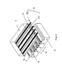
- Fig. 5 shows a schematic perspective view of a structure of a PDP on the market.
- the PDP is of a structure in which a front glass substrate 1 and back glass substrate 2 are adhered to each other.
- display electrodes 3 constituted of transparent electrodes 31 and bus electrodes 32 and the display electrodes 3 are covered with a dielectric layer 4.
- a protective layer 5 made of a MgO layer with a high secondary electron emission coefficient.
- Address electrodes 6 are provided on the back glass substrate 2 so as to intersect with the display electrodes at right angles.
- Barrier ribs 7 are provided between the address electrodes 6 in order to define light emitting regions and phosphors 8 for red, green and blue are coated on the address electrodes 6 in the respective regions divided by the barrier ribs 7.
- Ne-Xe gas is sealed in the interior of a space formed by adhering the front glass substrate 1 and the back glass substrate 2 to each other.
- Fig. 6 shows a state of a discharge cell in discharge as viewed in section.
- a voltage is applied between the display electrodes 3 each including a pair of two electrodes X and Y to form an electric field in a discharge space and to thereby excite Xe and generate gas discharge 9 and vacuum ultraviolet 10 is released therefrom.
- the ultraviolet 10 strikes the phosphor 8 to emit visible light 11.
- the discharge cell acts as a display by controlling the vacuum ultraviolet 10 in the electric field in the interior thereof. On this occasion, the vacuum ultraviolet 10 is directed to not only the phosphor 8 but also the front glass substrate 1.
- the protective layer (MgO layer) 5 and the dielectric layer 4 are formed on the front glass substrate 1 sequentially in the order starting at the discharge surface and since MgO passes a wavelength portion (165 nm or more) of the vacuum ultraviolet therethrough, part of the ultraviolet 10 reaches as far as the dielectric layer 4.
- the reference numbers 2 and 6 are the same as those in Fig. 5 in meaning.
- a method for forming a dielectric layer for use in a PDP generally known is a method in which it is formed by dispersing frit glass.
- the frit glass is provided as a paste obtained by dispersing a glass component into a vehicle made of ethyl cellulose resin as a main component.
- the frit glass in this form is coated on a substrate by printing and is baked to thereby burn out the resin component with the result of formation of a dielectric layer made of a glass component as a main component.
- a gas discharge panel substrate assembly comprising: electrodes formed on a substrate, a dielectric layer covering the electrodes, and a protective layer covering the dielectric layer and in contact with a discharge space, wherein the protective layer includes MgO and at least one compound selected from the group consisting of an Al compound, a Ti compound, a Y compound, a Zn compound, a Zr compound, a Ta compound and SiC.
- gas discharge panel substrate assembly comprising: electrodes formed on a substrate, a dielectric layer covering the electrodes, an intermediate layer covering the dielectric layer, and a protective layer covering the intermediate layer and in contact with a discharge space, wherein the protective layer includes MgO and the intermediate layer includes at least one compound selected from the group consisting of an Al compound, a Ti compound, a Y compound, a Zn compound, a Zr compound, a Ta compound and SiC.
- a production method for a gas discharge panel substrate assembly in which the dielectric layers of the first and second gas discharge panel substrate assemblies are formed with one of a CVD method, a plasma CVD method and a method in which a frit glass in the shape of a sheet is adhered on a substrate, followed by baking.
- a production method for a gas discharge panel substrate assembly in which the intermediate layer of the second gas discharge panel substrate assembly is formed with one of a vacuum evaporation method, a CVD method, a plasma CVD method, a sol-gel method and a binder method.
- a production method for a gas discharge panel substrate assembly in which the intermediate layer and the dielectric layer of the second gas discharge panel substrate assembly are continuously formed with a CVD method or a plasma CVD method.
- a production method for a gas discharge panel substrate assembly in which the intermediate layer and the protective layer of the second gas discharge panel substrate assembly are continuously formed with a vacuum evaporation method.
- an AC type gas discharge panel is provided-that uses the first or second gas discharge panel substrate assembly as a gas discharge panel substrate assembly in the front side.
- the inventors of the present invention have studied on a relationship between a method for forming a dielectric layer and a chromaticity of a PDP. As a result, it has been found that anomaly in chromaticity occurs in a case where a dielectric layer is formed with the method using frit glass in the shape of a sheet or the vapor phase film formation method such as a Plasma Enhanced CVD (PECVD) method.
- PECVD Plasma Enhanced CVD
- dielectric layers were formed in formation conditions shown in Table 1, thereafter a protective layer made of a MgO layer was formed by evaporation to a thickness of 1.0 ⁇ m and a PDP was formed in an ordinary process, followed by a display quality test on the PDP.
- Frit paste Sheet frit PECVD-SiO 2 Printing was performed on a glass substrate, after formation of electrodes, with a paste obtained by adding an ethyl cellulose binder to frit glass and the glass substrate with the print was baked in a conveyor type baking furnace under a heating program of 120 min at 350°C and then 30 min at 600°C to form a dielectric layer of 30 ⁇ m in thickness.
- a sheet obtained by adding an acrylic binder to frit glass is adhered on a glass substrate after formation of electrodes thereon and the glass substrate with the sheet was baked in a conveyor type baking furnace under a heating program of 240 min at 350°C and then 60 min at 600°C to form a dielectric layer of 30 ⁇ m in thickness.
- SiO 2 is formed as a dielectric layer on a glass substrate to a thickness of 5 ⁇ m in a parallel plate type PECVD apparatus under conditions of feeding SiH4 at a flow rate of 900 sccm, N 2 O at a flow rate of 9000 sccm, an RF output at 2.0 kW, a temperature at 400°C and a pressure at 3.0 Torr.
- White chromacity coordinates of a PDP under the conditions for forming a dielectric layer using the frit paste were (0.300, 0.300) in the CIE standard colorimetric system, while being (0.310, 0.285) in a case where the sheet frit was used and furthermore, the coordinates were also (0.320, 0.280) in a case of the PECVD-SiO 2 as well, the two latter of which display a reddish white color.
- This anomaly in chromaticity was found to be caused by degradation in green phosphor and a shift in chromaticity coordinates to follow, as a result of a study conducted by the inventors.
- discharge generated during a display test causes gas release from a dielectric layer formed with a sheet frit or PECVD and in turn the gas degrades phosphor.
- a gas source can be inferred to be a material, having a hydrocarbon bond, and remained in the layer without being burned out in the baking since the sheet layer prior to the formation of a dielectric layer obtained by using the sheet frit contains much of an organic component.
- the source inferred to be a material having bonds of hydrogen with silicon and/or carbon such as SiH 4 gas or Si(OC 2 H 5 ) 4 remaining in the layer as a material not reacted due to incomplete decomposition of a process raw gas. It is thought that the materials as the gas source are decomposed under an influence of ultraviolet generated by discharge to release hydrocarbon or hydrogen gas, and the gases pass through the MgO layer to then come out into a discharge space and degrade phosphor.
- the gases are activated by discharge so as to have a reducing ability; therefore, the activated gases are thought to reduce the protective layer (MgO).
- the reduced protective layer is colored and therefore deteriorated in transmittance. As the results, a luminance is thought to be degraded during panel display, causing a shift in chromaticity.
- the present invention has, to be concrete, one of features thereof that a protective layer has an ultraviolet shielding function (a first gas discharge substrate assembly) or alternatively, that an intermediate layer having an ultraviolet shielding function is inserted between a dielectric layer and a protective layer (a second gas discharge substrate assembly).
- the ultraviolet shielding function means a function capable of shielding ultraviolet having 200 nm or less in wavelength mainly.
- the protective layer covering the dielectric layer, and in contact with a discharge space is made of MgO for protecting the dielectric layer from a discharge electric field and at least one compound selected from the group consisting of an Al compound, a Ti compound, an Y compound, a Zn compound, a Zr compound, a Ta compound and SiC having the ultraviolet shielding function.
- Al compounds there are exemplified: alumina, aluminum nitride and others, as Ti compounds, there are exemplified: titania, titanium nitride and others, as Y compounds, there are exemplified: yttrium oxide, yttrium nitride and others, as Zn compounds, there are exemplified: zinc oxide, zinc nitride, zinc sulfide and others, as Zr compounds, there are exemplified: zirconium oxide, zirconium nitride and others and as Ta compounds, there are exemplified: tantalum oxide and others.
- the compound having the ultraviolet shielding function is preferably selected from the group consisting of Al 2 O 3 (alumina), AIN, TiO 2 (titania), Y 2 O 3 (yttrium oxide), ZnO (zinc oxide), ZrO 2 (zirconium oxide), Ta 2 O 5 (tantalum oxide) and SiC.
- Bandgaps of these compounds described above are shown in the following Table 2.
- VUV vacuum ultraviolet
- a mixing ratio of MgO and the compound having the ultraviolet shielding function is different according to a kind of a compound in use and the ratio is preferably in the range of from 95 to 85, to 5 to 15 in wt %. If a percentage of the compound having the ultraviolet shielding function is less than 5 wt %, it is not preferably since the ultraviolet shielding effect is reduced, while if the percentage of the compound is more than 15, it is not preferably either since a secondary electron emission ratio is decreased.
- a thickness of the protective layer is preferably in the range of form 0.5 to 1.5 ⁇ m.
- a method for forming a protective layer No specific limitation is imposed on a method for forming a protective layer but any of known methods in the technical field pertaining to the present invention can be used. There can be exemplified: a CVD method, a sputter method and a vacuum or an atmospheric evaporation method and among them, the vacuum evaporation method is preferably used.
- the CVD method is a method in which a raw gas (for example, a chloride) of a compound from which a protective layer is made is heated and decomposed to deposit a desired compound onto a substrate.
- a raw gas for example, a chloride
- the sputter method is a method in which a compound from which a protective layer is made is sputtered by an inert gas to deposit a desired compound onto a substrate.
- the evaporation method is a method in which a compound from which a protective layer is made is evaporated by heating with heating means such as an electron beam or the like to deposit a desired compound onto a substrate.
- the intermediate layer located between the dielectric layer and the protective layer is made of at least one compound compound selected from the group consisting of an Al compound, a Ti compound, an Y compound, a Zn compound, a Zr compound, a Ta compound and SiC, all having the ultraviolet shielding function.
- the compounds there are shown the same compounds as for the first gas discharge panel substrate assembly.
- preferable are compounds having 6.2 eV or less in bandgap.
- a thickness of the intermediate layer is preferably in the range of from 0.1 to 1 ⁇ m.
- a vacuum evaporation method As methods for forming the intermediate layer, there are exemplified: a vacuum evaporation method, a CVD method, a plasma CVD method, a sol-gel method, a binder method and others.
- the vacuum evaporation method is a method in which a compound from which an intermediate layer is made is heated and evaporated under a vacuum of 10 -3 to 10 -8 Torr with heating means such as an electron beam to deposit a desired compound onto a substrate.
- the CVD method is a method in which a raw gas (for example, a chloride) of a compound from which an intermediate layer is made is heated and decomposed by heating to deposit a desired compound onto a substrate.
- a raw gas for example, a chloride
- the plasma CVD method is a method in which a raw gas (for example, a chloride) of a compound from which an intermediate layer is made is decomposed with a plasma to deposit a desired compound onto a substrate.
- a raw gas for example, a chloride
- the sol-gel method is a method in which a solution containing a fatty acid salt or an alkoxide of a compound from which an intermediate layer is made is coated on a substrate to bake a coat on the substrate and to thereby form the intermediate layer.
- the binder method is a method in which a solution or a dispersion containing a compound from which an intermediate layer is made is coated on a substrate to bake a coat on the substrate and to thereby form the intermediate layer.
- the protective layer, formed on the intermediate layer, and in contact with the discharge space is preferably made of MgO and a thickness thereof is preferably in the range of from 0.5 to 1.5 ⁇ m.
- Methods for forming the protective layer can be methods similar to the methods for use in the first gas discharge panel substrate assembly.
- the protective layer By imparting the protective layer the ultraviolet shielding function, the number of production steps can be decreased compared with a construction in which the intermediate layer has an ultraviolet shielding function and as a result, a tact is improved and a cost is reduced.
- Structural members of the first and second gas discharge panel substrate assemblies other than the protective layer and the intermediate layer can be the same as each other.
- a substrate No specific limitation is imposed on a substrate, but any of known substrates in the technical field pertaining to the present invention can be used. To be concrete, there are exemplified: transparent substrates such as a glass substrate and a plastic substrate.
- an electrode formed on a substrate No specific limitation is imposed on an electrode formed on a substrate, but any of known electrodes in the technical field pertaining to the present invention can be used.
- transparent electrodes such as ITO and NESA.
- a metal electrode made of Cr, Cu or a stacked structure thereof may be formed on a transparent electrode in order to reduce a resistance of the transparent electrode.
- An arrangement of electrodes are formulated ordinarily in an array of stripes on a substrate, though being different according to a kind of a gas discharge panel.
- dielectric layer covering electrodes no specific limitation is imposed on a dielectric layer but any of known dielectric in the technical field pertaining to the present invention can be used. To be concrete, there are exemplified: layers made of a low-melting glass and SiO 2 .
- the low-melting glass exemplified in the first place can be formed using a frit paste or a sheet frit.
- the frit paste can be obtained by adding an ethyl cellulose binder and a solvent(arbitrary) to a low-melting glass (frit glass).
- the frit paste is coated at a prescribed position with a printing method or the like to bake the coat and to thereby obtain the dielectric layer.
- a sheet frit can be obtained by adding an acrylic binder to frit glass to form a mixture in the shape of a sheet.
- the sheet frit is adhered onto a substrate and then the sheet is baked to thereby transform the sheet into the dielectric layer.
- the dielectric layer made of a low-melting glass ordinarily has a thickness in the range of from 15 to 35 ⁇ m.
- SiO 2 which is exemplified in the second place, can be formed with a CVD method or a PECVD method.
- the SiO 2 dielectric layer can be formed such that, in a case of the PECVD method, a parallel plate type plasma CVD apparatus can be used to decompose a silane gas such as SiH 4 or Si 2 H 6 or a silicon containing compound such as tetraorthoethyl silicate (TEOS) with a plasma generated under conditions of an RF output in the range of from 1 to 2 kW, a temperature in the range of from 300 to 400°C and a pressure in the range of 1 to 3 in Torr.
- the SiO 2 dielectric layer also may be formed with an atmospheric CVD method.
- the dielectric layer made of SiO 2 ordinarily has a thickness in the range of from 5 to 15 ⁇ m.
- a method forming a dielectric layer using a sheet frit and vapor phase methods such as a CVD method and a PECVD method because of the following reason and easiness in production.
- a material having a hydrocarbon bond remains in the layer without burning out in baking. Furthermore, it is thought that in the vapor phase method, a material having bonds of silicon and/or carbon with hydrogen such as SiH 4 or Si(OC 2 H 5 ) 4 is not all decomposed and partly remains unreacted in the formed film. It is thought that the material is decomposed by ultraviolet generated by discharge to release hydrocarbon or hydrogen gas, and the gas passes through a MgO layer and is released into a discharge space to degrade a phosphor.
- the protective layer MgO layer
- the reduced protective layer is colored to degrade a transmittance. It is thought that with such results, a luminance is degraded during panel display to alter chromaticity.
- the ultraviolet shielding function is imparted to the protective layer of the first gas discharge panel substrate assembly and the intermediate layer of the second gas discharge panel substrate assembly. Therefore, it is prevented from occurring that ultraviolet generated in the discharge space reaches a dielectric layer, thereby enabling generation of hydrocarbon or hydrogen to be prevented.
- the intermediate layer and the dielectric layer may be formed continuously with a CVD method or a plasma CVD method, and the intermediate layer and the protective layer may be formed continuously with a vacuum evaporation method.
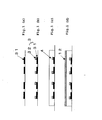
- Figs. 1(a) to 1(d) are schematic sectional views showing process steps from formation of the display electrodes (transparent electrodes and bus electrodes) to formation of a protective layer in the substrate side.
- Transparent electrodes 31 are at first formed on a glass substrate (Fig. 1(a)), subsequent to this bus electrodes (for example, a three layer structure of Cr/Cu/Cr) 32 are formed (Fig. 1(b)) and display electrodes (also referred to as sustaining electrodes) 3 are thereby formed.
- the transparent electrodes and the bus electrodes can be formed with a known method.
- a dielectric layer 4 covering display electrodes 3 is formed (Fig. 1(c)).
- methods for forming the dielectric layer 4 there are available a method in which a frit paste containing a frit glass or a sheet frit is used and a vapor phase method such as a CVD method.
- a protective layer 12 having the ultraviolet shielding function is formed at a final stage (Fig. 1(d)).
- methods for forming the protective layer 12 there can be used vapor phase film formation methods such as a CVD method, a vacuum or atmospheric evaporation method and a sputter method.
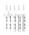
- Figs. 2(a) to 2(e) are schematic sectional views showing process steps from formation of display electrodes (a transparent electrodes and bus electrodes) to formation of a protective layer in the substrate side.
- Transparent electrodes 31 are at first formed on a glass substrate (Fig. 2(a)), subsequent to this bus electrodes 32 are formed (Fig. 2(b)) and display electrodes (also referred to as sustaining electrodes) 3 are thereby formed.
- the transparent electrodes and bus electrodes can be formed with a known method.
- a dielectric layer 4 covering the display electrodes 3 is formed (Fig. 2(c)).
- methods for forming the dielectric layer 4 there are available a method in which a frit paste containing a frit glass or a sheet frit is used and a vapor phase method such as a CVD method.
- an intermediate layer 13 having the ultraviolet shielding function is formed (Fig. 2(d)).
- a method for forming the intermediate layer 13 there can be used: a vacuum evaporation method, a CVD method, a sol-gel method, or a binder method.
- a protective layer 5 is formed at a final stage (Fig. 2(e)).
- methods for forming the protective layer 5 there are generally exemplified: vapor phase methods such as an evaporation method, a sputter method and others.
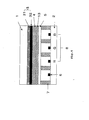
- PDPs of Figs. 3 and 4 are three-electrode AC type surface discharge PDPs.
- the PDPs illustrate cases where, in each case, sub-pixels (discharge cells) are formed with barrier ribs arranged in an array of stripes.
- the PDP of Fig. 3 is a PDP in which the first gas discharge panel substrate assembly is used and the PDP of Fig. 4 is a PDP in which the second gas discharge panel substrate assembly is used.
- the PDP of Fig. 3 is constituted of a front substrate and a back substrate.
- the first gas discharge panel substrate assembly obtained in the process of Fig. 1 is used as the front substrate as it is.
- the back substrate is generally constituted of: plural address electrodes 6 each in the shape of a stripe formed on a back glass substrate 2; plural barrier ribs 7 each in the shape of a stripe formed on the back glass substrate 2 between the adjacent address electrodes 6; and phosphors 8 formed between the barrier ribs 7 and on rib surfaces thereof.
- the phosphors 8 include: phosphors for red (R), green (G) and blue (B).
- the dielectric layer is formed on the back glass substrate 2 so as to cover the address electrodes 6 and the barrier ribs 7 may be formed on the dielectric layer.
- the dielectric layer can be formed in a similar way to that adopted in forming the dielectric layer in the front substrate side.
- the PDP of Fig. 4 has one of features that an ultraviolet shielding function is not imparted to the protective layer, as in the PDP of Fig. 3, but the intermediate layer having an ultraviolet shielding function is formed between the protective layer and the dielectric layer.
- the PDP of Fig. 4 is the same as the PDP of Fig. 3 with the exception of this particular structure.
- Example 1 (a dielectric layer constituted of a PECVD-SiO 2 and a protective layer having an ultraviolet shielding function constituted of simultaneous electron beam evaporation-MgO, and-ZrO 2, alumina, titania, Y 2 O 3, ZnS, Ta 2 O 5 or SiC)
- Transparent electrodes and bus electrodes were formed on a substrate in the front side, thereafter in a parallel plate type plasma CVD apparatus, a dielectric layer made of SiO 2 was formed to a film thickness of 5 ⁇ m under conditions of SiH 4 at a flow rate of 900 sccm, N 2 O at a flow rate of 9000 sccm, an RF output at 2.0 kW, a temperature at 400°C and a pressure at 3.0 Torr. Then, ZrO 2 and MgO were simultaneously deposited by electron beam evaporation to obtain a protective layer of a thickness of 1.0 ⁇ m. Thereafter, a PDP with the following specifications was fabricated by an ordinary process, followed by a display quality test on the PDP.
- White display at a load ratio of 10 % is measured with a luminance meter BM7 made by TOPCON CORPORATION.
- PDPs were fabricated in specifications and conditions similar to those described above with the exception that ZrO 2 was substituted for alumina, titania, Y 2 O 3, ZnS, Ta 2 O 5 or SiC. Coordinates of chromaticity of obtained PDPs are (0.301, 0.298), (0.301, 0.298), (0.303, 0.298), (0.302, 0.298), (0.300, 0.300) and (0.302, 0.298), which showed that degradation was suppressed.
- Example 2 (a dielectric layer constituted of a PECVD-SiO 2 and an intermediate layer constituted of electron beam evaporation-ZrO 2, alumina, titania, Y 2 O 3, ZnS, Ta 2 O 5 or SiC)
- Transparent electrodes and bus electrodes were formed on a substrate in the front side, thereafter in a parallel plate type plasma CVD apparatus, a dielectric layer made of SiO 2 was formed to a film thickness of 5 ⁇ m under conditions of SiH 4 at a flow rate of 900 sccm, N 2 O at a flow rate of 9000 sccm, an RF output at 2.0 kW, a temperature at 400°C and a pressure at 3.0 Torr. Then, an intermediate layer made of ZrO 2 was deposited by electron beam evaporation to a thickness of 0.3 ⁇ m. Subsequent to this a protective layer made of MgO is evaporation deposited to a thickness of 1.0 ⁇ m.
- PDPs were fabricated in specifications and conditions similar to those described above with the exception that intermediate layers were made of alumina, titania, Y 2 O 3, ZnS, Ta 2 O 5 and SiC respectively. Chromaticity coordinates were (0.302, 0.299), (0.302, 0.299), (0.301, 0.298), (0.301, 0.299), (0.300, 0.300) and (0.301, 0.299), which showed that degradation was suppressed.
- Example 3 (a dielectric layer constituted of a PECVD-SiO 2 and an intermediate layer constituted of a binder method titania-TiO 2 )
- Transparent electrodes and bus electrodes were formed on a substrate in the front side, thereafter in a parallel plate type plasma CVD apparatus, a dielectric layer made of SiO 2 was formed to a film thickness of 5 ⁇ m under conditions of SiH 4 at a flow rate of 900 sccm, N 2 O at a flow rate of 9000 sccm, an RF output at 2.0 kW, a temperature at 400°C and a pressure at 3.0 Torr.
- titania powder of 0.5 ⁇ m in average particle diameter was dispersed in a binder composed of 5 wt % ethylcellulose and 95 wt % terpineol, a coat was applied on the dielectric layer by a printing method, thereafter the coat was baked in the atmosphere at 400°C for 30 min to form an intermediate layer made of TiO 2 with a thickness of 3.0 ⁇ m.
- a protective layer made of MgO layer was deposited by evaporation to a thickness of 1.0 ⁇ m.
- a PDP was fabricated in specifications and conditions similar to those adopted in Example 1, followed by a display quality test on the PDP. As a result of the test, chromaticity coordinates were (0.301, 0.299), which showed that anomaly in chromaticity was suppressed.
- Example 4 (a dielectric layer constituted of a PECVD-SiO 2 and an intermediate layer constituted of a sol-gel method titania-TiO 2 )
- Transparent electrodes and bus electrodes were formed on a substrate in the front side, thereafter in a parallel plate type plasma CVD apparatus, a dielectric layer made of SiO 2 was formed to a film thickness of 5 ⁇ m under conditions of SiH 4 at a flow rate of 900 sccm, N 2 O at a flow rate of 9000 sccm, an RF output at 2.0 kW, a temperature at 400°C and a pressure at 3.0 Torr.
- Example 5 (a dielectric layer constituted of a PECVD-SiO 2 and an intermediate layer constituted of an atmospheric CVD titania of isopropyl titanate-TiO 2 )
- Transparent electrodes and bus electrodes were formed on a substrate in the front side, thereafter in a parallel plate type plasma CVD apparatus, a dielectric layer made of SiO 2 was formed to a film thickness of 5 ⁇ m under conditions of SiH 4 at a flow rate of 900 sccm, N 2 O at a flow rate of 9000 sccm, an RF output at 2.0 kW, a temperature at 400°C and a pressure at 3.0 Torr.
- an intermediate layer made of TiO 2 of 1.0 ⁇ m in thickness was formed under conditions of Ti[COH(CH 3 ) 2 ] 4 at a flow rate of 100 sccm, O 2 at a flow rate of 500 sccm and a substrate temperature at 400°C.
- a protective layer made of MgO layer was deposited by evaporation to a thickness of 1.0 ⁇ m.
- a PDP was fabricated in specifications and conditions similar to those adopted in Example 1, followed by a display quality test on the PDP. As a result of the test, chromaticity coordinates were (0.301, 0.298), which showed that anomaly in chromaticity was suppressed.
- Example 6 (a dielectric layer constituted of a PECVD-SiO 2 and an intermediate layer constituted of an atmospheric CVD. titania of titanium tetrachloride-TiO 2 )
- Transparent electrodes and bus electrodes were formed on a substrate in the front side, thereafter in a parallel plate type plasma CVD apparatus, a dielectric layer made of SiO 2 was formed to a film thickness of 5 ⁇ m under conditions of SiH 4 at a flow rate of 900 sccm, N 2 O at a flow rate of 9000 sccm, an RF output at 2.0 kW, a temperature at 400°C and a pressure at 3.0 Torr. Then, in an atmospheric CVD apparatus, an intermediate layer made of TiO 2 of 0.3 ⁇ m in thickness was formed under conditions of TiCl 4 at a flow rate of 100 sccm, O 2 at a flow rate of 500 sccm and a substrate temperature at 400°C.
- a protective layer made of MgO layer was deposited by evaporation to a thickness of 1.0 ⁇ m.
- a PDP was fabricated in specifications and conditions similar to those adopted in Example 1, followed by a display quality test on the PDP.
- chromaticity coordinates were (0.301, 0.298), which showed that anomaly in chromaticity was suppressed.
- Example 7 (a dielectric layer constituted of a PECVD-SiO 2 and an intermediate layer constituted of an atmospheric CVD of zirconium tetrachloride-ZrO 2 )
- Transparent electrodes and bus electrodes were formed on a substrate in the front side, thereafter in a parallel plate type plasma CVD apparatus, a dielectric layer made of SiO 2 was formed to a film thickness of 5 ⁇ m under conditions of SiH 4 at a flow rate of 900 sccm, N 2 O at a flow rate of 9000 sccm, an RF output at 2.0 kW, a temperature at 400°C and a pressure at 3.0 Torr. Then, in an atmospheric CVD apparatus, an intermediate layer made of ZrO 2 of 0.3 ⁇ m in thickness was formed under conditions of ZrCl 4 at a flow rate of 100 sccm, O 2 at a flow rate of 500 sccm and a substrate temperature at 480°C.
- a protective layer made of MgO layer was deposited by evaporation to a thickness of 1.0 ⁇ m.
- a PDP was fabricated in specifications and conditions similar to those adopted in Example 1, followed by a display quality test on the PDP.
- chromaticity coordinates were (0.301, 0.299), which showed that anomaly in chromaticity was suppressed.
- Example 8 (a dielectric layer constituted of a PECVD-SiO 2 and an intermediate layer constituted of a plasma CVD alumina-Al 2 O 3 )
- Transparent electrodes and bus electrodes were formed on a substrate in the front side, thereafter in a parallel plate type plasma CVD apparatus, a dielectric layer made of SiO 2 was formed to a film thickness of 5 ⁇ m under conditions of SiH 4 at a flow rate of 900 sccm, N 2 O at a flow rate of 9000 sccm, an RF output at 2.0 kW, a temperature at 400°C and a pressure at 3.0 Torr and successively, in the same apparatus, an intermediate layer made of Al 2 O 3 of 0.3 ⁇ m in thickness was formed under conditions of AlCl 3 at a flow rate of 100 sccm, CO 2 at a flow rate of 1000 sccm, H 2 at flow rate of 500 sccm, an RF output at 2.0 kW, a temperature at 400°C and a pressure at 3.0 Torr.
- a protective layer made of MgO layer was deposited by evaporation to a thickness of 1.0 ⁇ m.
- a PDP was fabricated in specifications and conditions similar to those adopted in Example 1, followed by a display quality test on the PDP.
- chromaticity coordinates were (0.301, 0.300), which showed that anomaly in chromaticity was suppressed.
- Example 9 (a dielectric layer constituted of a sheet frit-low-melting glass and an intermediate layer constituted of an electron beam evaporation-ZrO 2 )
- Transparent electrodes and bus electrodes were formed on a substrate in the front side, thereafter an acrylic binder was added to frit glass made of PbO-B 2 O 5 -SiO 2 to process the mixture into a sheet, the sheet was adhered onto the substrate and baked in a conveyor type baking furnace under a heating program of 240 min at 350°C and thereafter 60 min at 600°C, thereby forming an dielectric layer of 30 ⁇ m in thickness. Then, an intermediate layer made of ZrO 2 was formed with electron beam evaporation to a thickness of 0.3 ⁇ m. Subsequent to this a protective layer made of MgO layer was deposited by evaporation to a thickness of 1.0 ⁇ m.
- Example 10 (a dielectric layer constituted of a PECVD-SiO 2 and an intermediate layer constituted of an electron beam evaporation-ZrO 2 )
- Transparent electrodes and bus electrodes were formed on a substrate in the front side, thereafter in a parallel plate type plasma CVD apparatus, a dielectric layer made of SiO 2 was formed to a film thickness of 5 ⁇ m under conditions of TEOS at a flow rate of 800 sccm, O 2 at a flow rate of 2000 sccm, an RF output at 1.5 kW, a temperature at 350°C and a pressure at 1.0 Torr. Note that dielectric layers formed on a silicon substrate and a soda lime substrate had stresses of-0.7E9 dyn/cm 2 and -1.9 dyn/cm 2 , respectively.
- an intermediate layer made of ZrO 2 was deposited to a thickness of 0.3 ⁇ m by electron beam evaporation.
- a protective layer made of MgO layer was deposited by evaporation to a thickness of 1.0 ⁇ m.
- Example 11 (a dielectric layer constituted of a CVD-SiO 2 and an intermediate layer constituted of an electron beam evaporation-ZrO 2 )
- Transparent electrodes and bus electrodes were formed on a substrate in the front side, thereafter in an atmospheric CVD apparatus, a dielectric layer made of SiO 2 was formed to a film thickness of 5 ⁇ m under conditions of SiH 4 at a flow rate of 1000 sccm, N 2 O at a flow rate of 10000 sccm, and a temperature at 450°C.
- dielectric layers formed on a silicon substrate and a soda lime substrate had stresses of +4E9 dyn/cm 2 and +2.3 dyn/cm 2 , respectively.
- an intermediate layer made of ZrO 2 was deposited to a thickness of 0.3 ⁇ m by electron beam evaporation.
- a protective layer made of MgO layer was deposited by evaporation to a thickness of 1.0 ⁇ m.
- Example 12 (a dielectric layer constituted of a CVD-SiO 2 and an intermediate layer constituted of a plasma CVD tantalum oxide-Ta 2 O 5 )
- Transparent electrodes and bus electrodes were formed on a substrate in the front side, thereafter in a parallel plate type plasma CVD apparatus, a dielectric layer made of SiO 2 was formed to a film thickness of 5 ⁇ m under conditions of SiH 4 at a flow rate of 900 sccm, N 2 O at a flow rate of 9000 sccm, an RF output at 2.0 kW, a temperature at 400°C and a pressure at 3.0 Torr.
- an intermediate layer made of Ta 2 O 5 of 0.2 ⁇ m in thickness was formed under conditions of Ta(C 2 H 5 OH) 5 at a flow rate of 200 sccm (supplied directly after evaporation), O 2 at a flow rate of 1000 sccm, an RF output at 2.0 kW, a temperature at 400°C and a pressure at 4.0 Torr.
- a protective layer made of MgO layer was deposited by evaporation to a thickness of 1.0 ⁇ m.
- a structure can also be included in which a substrate provided with a dielectric layer, barrier ribs and phosphor layers thereon is arranged in the front side and a substrate provided with a protective layer and others thereon is arranged in the back side.
- Another structure can also be included in which address electrodes are covered with a dielectric layer, and barrier ribs and phosphor layers are formed on the dielectric layer, in which case a surface of the dielectric layer is desirably covered with an ultraviolet shielding film.
- the present invention can also be applied to two-electrode AC type opposite discharge PDP.
- the present invention by imparting a protective layer itself an ultraviolet shielding function or inserting an intermediate layer having an ultraviolet shielding function between a protective layer and a dielectric layer, vacuum ultraviolet generated during discharge is prevented from reaching the dielectric layer, thereby disabling disconnection of a hydrocarbon bond in the dielectric layer. Therefore, since suppression can be realized of reduction of phosphor and the protective layer caused by hydrogen generated by the disconnection, there can be obtained a gas discharge panel without degradation of phosphor.
Landscapes
- Engineering & Computer Science (AREA)
- Physics & Mathematics (AREA)
- Plasma & Fusion (AREA)
- Manufacturing & Machinery (AREA)
- Gas-Filled Discharge Tubes (AREA)
Abstract
Description
- The present invention relates to a gas discharge panel substrate assembly, a production method therefore and an AC type gas discharge panel.
- There have been reported on various types of gas discharge panels, among which an AC type plasma display panel (PDP) of a three-electrode surface discharge structure has been introduced to the market.
- Fig. 5 shows a schematic perspective view of a structure of a PDP on the market. The PDP is of a structure in which a
front glass substrate 1 andback glass substrate 2 are adhered to each other. Provided on thefront glass substrate 1 aredisplay electrodes 3 constituted oftransparent electrodes 31 andbus electrodes 32 and thedisplay electrodes 3 are covered with adielectric layer 4. Further formed on thedielectric layer 4 is aprotective layer 5 made of a MgO layer with a high secondary electron emission coefficient.Address electrodes 6 are provided on theback glass substrate 2 so as to intersect with the display electrodes at right angles.Barrier ribs 7 are provided between theaddress electrodes 6 in order to define light emitting regions andphosphors 8 for red, green and blue are coated on theaddress electrodes 6 in the respective regions divided by thebarrier ribs 7. Ne-Xe gas is sealed in the interior of a space formed by adhering thefront glass substrate 1 and theback glass substrate 2 to each other. - Fig. 6 shows a state of a discharge cell in discharge as viewed in section. A voltage is applied between the
display electrodes 3 each including a pair of two electrodes X and Y to form an electric field in a discharge space and to thereby excite Xe and generategas discharge 9 andvacuum ultraviolet 10 is released therefrom. Theultraviolet 10 strikes thephosphor 8 to emit visible light 11. The discharge cell acts as a display by controlling thevacuum ultraviolet 10 in the electric field in the interior thereof. On this occasion, thevacuum ultraviolet 10 is directed to not only thephosphor 8 but also thefront glass substrate 1. The protective layer (MgO layer) 5 and thedielectric layer 4 are formed on thefront glass substrate 1 sequentially in the order starting at the discharge surface and since MgO passes a wavelength portion (165 nm or more) of the vacuum ultraviolet therethrough, part of theultraviolet 10 reaches as far as thedielectric layer 4. In Fig. 6, thereference numbers - As a method for forming a dielectric layer for use in a PDP, generally known is a method in which it is formed by dispersing frit glass. The frit glass is provided as a paste obtained by dispersing a glass component into a vehicle made of ethyl cellulose resin as a main component. The frit glass in this form is coated on a substrate by printing and is baked to thereby burn out the resin component with the result of formation of a dielectric layer made of a glass component as a main component. Furthermore, as methods for forming a dielectric layer more suitable for mass production in recent years, there have been proposed: a method in which frit glass in the shape of a sheet obtained by dispersing frit glass in acrylic resin or the like is adhered and baked and a method to use vapor phase film formation such as a CVD method.
- It is desirable to provide a gas discharge panel substrate assembly and a gas discharge panel causing no or little phosphor degradation phenomenon, as well as production methods therefor.
- According to an aspect of the present invention there is provided a gas discharge panel substrate assembly comprising: electrodes formed on a substrate, a dielectric layer covering the electrodes, and a protective layer covering the dielectric layer and in contact with a discharge space, wherein the protective layer includes MgO and at least one compound selected from the group consisting of an Al compound, a Ti compound, a Y compound, a Zn compound, a Zr compound, a Ta compound and SiC.
- Furthermore, another aspect of the present invention provides gas discharge panel substrate assembly comprising: electrodes formed on a substrate, a dielectric layer covering the electrodes, an intermediate layer covering the dielectric layer, and a protective layer covering the intermediate layer and in contact with a discharge space, wherein the protective layer includes MgO and the intermediate layer includes at least one compound selected from the group consisting of an Al compound, a Ti compound, a Y compound, a Zn compound, a Zr compound, a Ta compound and SiC.
- Moreover, according to the present invention, a production method for a gas discharge panel substrate assembly is provided, in which the dielectric layers of the first and second gas discharge panel substrate assemblies are formed with one of a CVD method, a plasma CVD method and a method in which a frit glass in the shape of a sheet is adhered on a substrate, followed by baking.
- Besides, according to the present invention, a production method for a gas discharge panel substrate assembly is provided, in which the intermediate layer of the second gas discharge panel substrate assembly is formed with one of a vacuum evaporation method, a CVD method, a plasma CVD method, a sol-gel method and a binder method.
- Furthermore, according to the present invention, a production method for a gas discharge panel substrate assembly is provided, in which the intermediate layer and the dielectric layer of the second gas discharge panel substrate assembly are continuously formed with a CVD method or a plasma CVD method.
- Moreover, according to the present invention, a production method for a gas discharge panel substrate assembly is provided, in which the intermediate layer and the protective layer of the second gas discharge panel substrate assembly are continuously formed with a vacuum evaporation method.
- Besides, according to the present invention, an AC type gas discharge panel is provided-that uses the first or second gas discharge panel substrate assembly as a gas discharge panel substrate assembly in the front side.
- These and other objects of the present application will become more readily apparent from the detailed description given hereinafter. However, it should be understood that the detailed description and specific examples, while indicating preferred embodiments of the invention, are given by way of illustration only, since various changes and modifications within the scope of the invention will become apparent to those skilled in the art from this detailed description.
- Fig. 1(a) to 1(d) are schematic sectional views showing process steps from formation of the gas discharge panel substrate assembly of the present invention;
- Figs.2 (a) to 2(e) are schematic sectional views showing process steps from formation of the gas discharge panel substrate assembly of the present invention;
- Fig.3 is a schematic sectional view of the gas discharge panel of the present invention;
- Fig.4 is a schematic sectional view of the gas discharge panel of the present invention;
- Fig. 5 is a schematic perspective view of a structure of a PDP of prior art;
- Fig.6. is a schematic view of a state of a discharge panel in discharge.
-
- The inventors of the present invention have studied on a relationship between a method for forming a dielectric layer and a chromaticity of a PDP. As a result, it has been found that anomaly in chromaticity occurs in a case where a dielectric layer is formed with the method using frit glass in the shape of a sheet or the vapor phase film formation method such as a Plasma Enhanced CVD (PECVD) method. To be concrete, dielectric layers were formed in formation conditions shown in Table 1, thereafter a protective layer made of a MgO layer was formed by evaporation to a thickness of 1.0 µm and a PDP was formed in an ordinary process, followed by a display quality test on the PDP.
Frit paste Sheet frit PECVD-SiO2 Printing was performed on a glass substrate, after formation of electrodes, with a paste obtained by adding an ethyl cellulose binder to frit glass and the glass substrate with the print was baked in a conveyor type baking furnace under a heating program of 120 min at 350°C and then 30 min at 600°C to form a dielectric layer of 30 µm in thickness. A sheet obtained by adding an acrylic binder to frit glass is adhered on a glass substrate after formation of electrodes thereon and the glass substrate with the sheet was baked in a conveyor type baking furnace under a heating program of 240 min at 350°C and then 60 min at 600°C to form a dielectric layer of 30 µm in thickness. After formation of electrodes the glass substrate, SiO2 is formed as a dielectric layer on a glass substrate to a thickness of 5 µm in a parallel plate type PECVD apparatus under conditions of feeding SiH4 at a flow rate of 900 sccm, N2O at a flow rate of 9000 sccm, an RF output at 2.0 kW, a temperature at 400°C and a pressure at 3.0 Torr. - White chromacity coordinates of a PDP under the conditions for forming a dielectric layer using the frit paste were (0.300, 0.300) in the CIE standard colorimetric system, while being (0.310, 0.285) in a case where the sheet frit was used and furthermore, the coordinates were also (0.320, 0.280) in a case of the PECVD-SiO2 as well, the two latter of which display a reddish white color. This anomaly in chromaticity was found to be caused by degradation in green phosphor and a shift in chromaticity coordinates to follow, as a result of a study conducted by the inventors.
- It is inferred that discharge generated during a display test causes gas release from a dielectric layer formed with a sheet frit or PECVD and in turn the gas degrades phosphor.
- A gas source can be inferred to be a material, having a hydrocarbon bond, and remained in the layer without being burned out in the baking since the sheet layer prior to the formation of a dielectric layer obtained by using the sheet frit contains much of an organic component. Likewise, in the PECVD method, the source can be inferred to be a material having bonds of hydrogen with silicon and/or carbon such as SiH4 gas or Si(OC2H5)4 remaining in the layer as a material not reacted due to incomplete decomposition of a process raw gas. It is thought that the materials as the gas source are decomposed under an influence of ultraviolet generated by discharge to release hydrocarbon or hydrogen gas, and the gases pass through the MgO layer to then come out into a discharge space and degrade phosphor. The gases are activated by discharge so as to have a reducing ability; therefore, the activated gases are thought to reduce the protective layer (MgO). The reduced protective layer is colored and therefore deteriorated in transmittance. As the results, a luminance is thought to be degraded during panel display, causing a shift in chromaticity.
- The present invention has, to be concrete, one of features thereof that a protective layer has an ultraviolet shielding function (a first gas discharge substrate assembly) or alternatively, that an intermediate layer having an ultraviolet shielding function is inserted between a dielectric layer and a protective layer (a second gas discharge substrate assembly). The ultraviolet shielding function means a function capable of shielding ultraviolet having 200 nm or less in wavelength mainly.
- In the first gas discharge panel substrate assembly, the protective layer, covering the dielectric layer, and in contact with a discharge space is made of MgO for protecting the dielectric layer from a discharge electric field and at least one compound selected from the group consisting of an Al compound, a Ti compound, an Y compound, a Zn compound, a Zr compound, a Ta compound and SiC having the ultraviolet shielding function.
- As Al compounds, there are exemplified: alumina, aluminum nitride and others, as Ti compounds, there are exemplified: titania, titanium nitride and others, as Y compounds, there are exemplified: yttrium oxide, yttrium nitride and others, as Zn compounds, there are exemplified: zinc oxide, zinc nitride, zinc sulfide and others, as Zr compounds, there are exemplified: zirconium oxide, zirconium nitride and others and as Ta compounds, there are exemplified: tantalum oxide and others.
- The compound having the ultraviolet shielding function is preferably selected from the group consisting of Al2O3 (alumina), AIN, TiO2 (titania), Y2O3 (yttrium oxide), ZnO (zinc oxide), ZrO2 (zirconium oxide), Ta2O5 (tantalum oxide) and SiC. Bandgaps of these compounds described above are shown in the following Table 2.
Bandgaps(eV) MgO 8 Al2O3 7.4 AlN 3.8 TiO2 3.0 Y2O3 2.43 ZnO 3.2 ZnS 3.7 ZrO2 5.16 Ta2O5 4.2 SiC 3 - Compounds having a bandgap of 6.2 eV or less among the compounds described above are preferably used since the compounds exert a vacuum ultraviolet (VUV) shielding effect.
- A mixing ratio of MgO and the compound having the ultraviolet shielding function is different according to a kind of a compound in use and the ratio is preferably in the range of from 95 to 85, to 5 to 15 in wt %. If a percentage of the compound having the ultraviolet shielding function is less than 5 wt %, it is not preferably since the ultraviolet shielding effect is reduced, while if the percentage of the compound is more than 15, it is not preferably either since a secondary electron emission ratio is decreased.
- No specific limitation is imposed on a thickness of the protective layer as far as a prescribed function is exerted, but it is preferably in the range of form 0.5 to 1.5 µm.
- No specific limitation is imposed on a method for forming a protective layer but any of known methods in the technical field pertaining to the present invention can be used. There can be exemplified: a CVD method, a sputter method and a vacuum or an atmospheric evaporation method and among them, the vacuum evaporation method is preferably used.
- The CVD method is a method in which a raw gas (for example, a chloride) of a compound from which a protective layer is made is heated and decomposed to deposit a desired compound onto a substrate.
- The sputter method is a method in which a compound from which a protective layer is made is sputtered by an inert gas to deposit a desired compound onto a substrate.
- The evaporation method is a method in which a compound from which a protective layer is made is evaporated by heating with heating means such as an electron beam or the like to deposit a desired compound onto a substrate.
- On the other hand, in the second gas discharge panel substrate assembly, the intermediate layer located between the dielectric layer and the protective layer is made of at least one compound compound selected from the group consisting of an Al compound, a Ti compound, an Y compound, a Zn compound, a Zr compound, a Ta compound and SiC, all having the ultraviolet shielding function. As concrete examples of the compounds, there are shown the same compounds as for the first gas discharge panel substrate assembly. Furthermore, similar to the first discharge panel substrate assembly, preferable are compounds having 6.2 eV or less in bandgap.
- No specific limitation is imposed on a thickness of the intermediate layer as far as a prescribed function is exerted but it is preferably in the range of from 0.1 to 1 µm.
- As methods for forming the intermediate layer, there are exemplified: a vacuum evaporation method, a CVD method, a plasma CVD method, a sol-gel method, a binder method and others.
- The vacuum evaporation method is a method in which a compound from which an intermediate layer is made is heated and evaporated under a vacuum of 10-3 to 10-8 Torr with heating means such as an electron beam to deposit a desired compound onto a substrate.
- The CVD method is a method in which a raw gas (for example, a chloride) of a compound from which an intermediate layer is made is heated and decomposed by heating to deposit a desired compound onto a substrate.
- The plasma CVD method is a method in which a raw gas (for example, a chloride) of a compound from which an intermediate layer is made is decomposed with a plasma to deposit a desired compound onto a substrate.
- The sol-gel method is a method in which a solution containing a fatty acid salt or an alkoxide of a compound from which an intermediate layer is made is coated on a substrate to bake a coat on the substrate and to thereby form the intermediate layer.
- The binder method is a method in which a solution or a dispersion containing a compound from which an intermediate layer is made is coated on a substrate to bake a coat on the substrate and to thereby form the intermediate layer.
- Note that in the second gas discharge panel substrate assembly, the protective layer, formed on the intermediate layer, and in contact with the discharge space is preferably made of MgO and a thickness thereof is preferably in the range of from 0.5 to 1.5 µm. Methods for forming the protective layer can be methods similar to the methods for use in the first gas discharge panel substrate assembly.
- By imparting the protective layer the ultraviolet shielding function, the number of production steps can be decreased compared with a construction in which the intermediate layer has an ultraviolet shielding function and as a result, a tact is improved and a cost is reduced.
- Structural members of the first and second gas discharge panel substrate assemblies other than the protective layer and the intermediate layer can be the same as each other.
- No specific limitation is imposed on a substrate, but any of known substrates in the technical field pertaining to the present invention can be used. To be concrete, there are exemplified: transparent substrates such as a glass substrate and a plastic substrate.
- No specific limitation is imposed on an electrode formed on a substrate, but any of known electrodes in the technical field pertaining to the present invention can be used. To be concrete, there are exemplified transparent electrodes such as ITO and NESA. Furthermore, a metal electrode made of Cr, Cu or a stacked structure thereof may be formed on a transparent electrode in order to reduce a resistance of the transparent electrode. An arrangement of electrodes are formulated ordinarily in an array of stripes on a substrate, though being different according to a kind of a gas discharge panel.
- As the dielectric layer covering electrodes, no specific limitation is imposed on a dielectric layer but any of known dielectric in the technical field pertaining to the present invention can be used. To be concrete, there are exemplified: layers made of a low-melting glass and SiO2.
- The low-melting glass exemplified in the first place can be formed using a frit paste or a sheet frit. The frit paste can be obtained by adding an ethyl cellulose binder and a solvent(arbitrary) to a low-melting glass (frit glass). The frit paste is coated at a prescribed position with a printing method or the like to bake the coat and to thereby obtain the dielectric layer. A sheet frit can be obtained by adding an acrylic binder to frit glass to form a mixture in the shape of a sheet. The sheet frit is adhered onto a substrate and then the sheet is baked to thereby transform the sheet into the dielectric layer. The dielectric layer made of a low-melting glass ordinarily has a thickness in the range of from 15 to 35 µm.
- SiO2, which is exemplified in the second place, can be formed with a CVD method or a PECVD method. To be concrete, the SiO2 dielectric layer can be formed such that, in a case of the PECVD method, a parallel plate type plasma CVD apparatus can be used to decompose a silane gas such as SiH4 or Si2H6 or a silicon containing compound such as tetraorthoethyl silicate (TEOS) with a plasma generated under conditions of an RF output in the range of from 1 to 2 kW, a temperature in the range of from 300 to 400°C and a pressure in the range of 1 to 3 in Torr. The SiO2 dielectric layer also may be formed with an atmospheric CVD method. The dielectric layer made of SiO2 ordinarily has a thickness in the range of from 5 to 15 µm.
- Among the methods for forming the dielectric layer, preferable are a method forming a dielectric layer using a sheet frit and vapor phase methods such as a CVD method and a PECVD method because of the following reason and easiness in production.
- In the dielectric layer formed with a sheet frit among the dielectric layers described above, since much of an organic component is contained in a sheet layer prior to the formation, it is inferred that a material having a hydrocarbon bond remains in the layer without burning out in baking. Furthermore, it is thought that in the vapor phase method, a material having bonds of silicon and/or carbon with hydrogen such as SiH4 or Si(OC2H5)4 is not all decomposed and partly remains unreacted in the formed film. It is thought that the material is decomposed by ultraviolet generated by discharge to release hydrocarbon or hydrogen gas, and the gas passes through a MgO layer and is released into a discharge space to degrade a phosphor. Furthermore, it is thought that since the gas is activated by discharge so as to have a reducing ability, the protective layer (MgO layer) is also reduced. The reduced protective layer is colored to degrade a transmittance. It is thought that with such results, a luminance is degraded during panel display to alter chromaticity. In the present invention, the ultraviolet shielding function is imparted to the protective layer of the first gas discharge panel substrate assembly and the intermediate layer of the second gas discharge panel substrate assembly. Therefore, it is prevented from occurring that ultraviolet generated in the discharge space reaches a dielectric layer, thereby enabling generation of hydrocarbon or hydrogen to be prevented.
- Note that since even in a case where a frit paste is used as well, it is thought that a material having a hydrocarbon bond exists in the dielectric layer, a construction of the present invention is useful.
- In formation of the protective layer, and intermediate layer and dielectric layer, all described above, the intermediate layer and the dielectric layer may be formed continuously with a CVD method or a plasma CVD method, and the intermediate layer and the protective layer may be formed continuously with a vacuum evaporation method. By forming continuously, reduction in production time can be achieved and mixing into of an impurity to layers can be prevented.
- Description will be given of an example of a production method for a first gas discharge panel substrate assembly of the present invention below with reference to Figs. 1(a) to 1(d). Figs. 1(a) to 1(d) are schematic sectional views showing process steps from formation of the display electrodes (transparent electrodes and bus electrodes) to formation of a protective layer in the substrate side.
-
Transparent electrodes 31 are at first formed on a glass substrate (Fig. 1(a)), subsequent to this bus electrodes (for example, a three layer structure of Cr/Cu/Cr) 32 are formed (Fig. 1(b)) and display electrodes (also referred to as sustaining electrodes) 3 are thereby formed. The transparent electrodes and the bus electrodes can be formed with a known method. - Then, a
dielectric layer 4covering display electrodes 3 is formed (Fig. 1(c)). As methods for forming thedielectric layer 4, there are available a method in which a frit paste containing a frit glass or a sheet frit is used and a vapor phase method such as a CVD method. - A
protective layer 12 having the ultraviolet shielding function is formed at a final stage (Fig. 1(d)). As methods for forming theprotective layer 12, there can be used vapor phase film formation methods such as a CVD method, a vacuum or atmospheric evaporation method and a sputter method. - Then, description will be given of an example of a production method for a second gas discharge panel substrate assembly of the present invention below with reference to Figs. 2(a) to 2(e). Figs. 2(a) to 2(e) are schematic sectional views showing process steps from formation of display electrodes (a transparent electrodes and bus electrodes) to formation of a protective layer in the substrate side.
-
Transparent electrodes 31 are at first formed on a glass substrate (Fig. 2(a)), subsequent to thisbus electrodes 32 are formed (Fig. 2(b)) and display electrodes (also referred to as sustaining electrodes) 3 are thereby formed. The transparent electrodes and bus electrodes can be formed with a known method. - Then, a
dielectric layer 4 covering thedisplay electrodes 3 is formed (Fig. 2(c)). As methods for forming thedielectric layer 4, there are available a method in which a frit paste containing a frit glass or a sheet frit is used and a vapor phase method such as a CVD method. - Then, an
intermediate layer 13 having the ultraviolet shielding function is formed (Fig. 2(d)). As a method for forming theintermediate layer 13, there can be used: a vacuum evaporation method, a CVD method, a sol-gel method, or a binder method. - A
protective layer 5 is formed at a final stage (Fig. 2(e)). As methods for forming theprotective layer 5, there are generally exemplified: vapor phase methods such as an evaporation method, a sputter method and others. - Then, description will be given of a structure of a gas discharge panel (PDP) in a case where a gas discharge panel substrate assembly of the present invention is used in the front side below with reference to Figs. 3 and 4.
- PDPs of Figs. 3 and 4 are three-electrode AC type surface discharge PDPs. The PDPs illustrate cases where, in each case, sub-pixels (discharge cells) are formed with barrier ribs arranged in an array of stripes. The PDP of Fig. 3 is a PDP in which the first gas discharge panel substrate assembly is used and the PDP of Fig. 4 is a PDP in which the second gas discharge panel substrate assembly is used.
- The PDP of Fig. 3 is constituted of a front substrate and a back substrate.
- The first gas discharge panel substrate assembly obtained in the process of Fig. 1 is used as the front substrate as it is.
- Then, the back substrate is generally constituted of:
plural address electrodes 6 each in the shape of a stripe formed on aback glass substrate 2;plural barrier ribs 7 each in the shape of a stripe formed on theback glass substrate 2 between theadjacent address electrodes 6; andphosphors 8 formed between thebarrier ribs 7 and on rib surfaces thereof. In Fig. 3, thephosphors 8 include: phosphors for red (R), green (G) and blue (B). - Furthermore, the dielectric layer is formed on the
back glass substrate 2 so as to cover theaddress electrodes 6 and thebarrier ribs 7 may be formed on the dielectric layer. The dielectric layer can be formed in a similar way to that adopted in forming the dielectric layer in the front substrate side. - The PDP of Fig. 4 has one of features that an ultraviolet shielding function is not imparted to the protective layer, as in the PDP of Fig. 3, but the intermediate layer having an ultraviolet shielding function is formed between the protective layer and the dielectric layer. The PDP of Fig. 4 is the same as the PDP of Fig. 3 with the exception of this particular structure.
- While description will be given of the present invention below with examples and comparative examples in a further concrete manner, no limitation is placed on conditions for forming a film, thickness values of films, materials and others used therein.
- Transparent electrodes and bus electrodes were formed on a substrate in the front side, thereafter in a parallel plate type plasma CVD apparatus, a dielectric layer made of SiO2 was formed to a film thickness of 5 µm under conditions of SiH4 at a flow rate of 900 sccm, N2O at a flow rate of 9000 sccm, an RF output at 2.0 kW, a temperature at 400°C and a pressure at 3.0 Torr. Then, ZrO2 and MgO were simultaneously deposited by electron beam evaporation to obtain a protective layer of a thickness of 1.0 µm. Thereafter, a PDP with the following specifications was fabricated by an ordinary process, followed by a display quality test on the PDP.
-
- a screen size: 42 inch
- the number of pixels: 852 x 480 (VGA)
- the number of sub-pixels: 2556 x 480
- a sub-pixel size: 1080 µm x 390 µm
- material of front substrate: soda lime glass
- thickness of front substrate: 3 mm
- width of transparent electrode: 275 µm
- width of bus electrode: 100 µm
- surface discharge gap: 100 µm
- width of light shielding layer between transparent electrodes: 350 µm
- width of barrier rib: 70µm
- height of barrier rib: 140 µm
- barrier rib pitch: 360 µm
- kinds of phosphors: PDP standard RGB phosphors, red (Y, Gd)BO3: Eu, green Zn2SiO4:Mn, blue BaMgAl10O17:Eu
- driving conditions: 25 kHz at 180 V
-
- White display at a load ratio of 10 % is measured with a luminance meter BM7 made by TOPCON CORPORATION.
- As a result of the test, chromaticity coordinates in the CIE standard colorimetric system were (0.300, 0.301) and anomaly in chromaticity was suppressed.
- Furthermore, PDPs were fabricated in specifications and conditions similar to those described above with the exception that ZrO2 was substituted for alumina, titania, Y2O3, ZnS, Ta2O5 or SiC. Coordinates of chromaticity of obtained PDPs are (0.301, 0.298), (0.301, 0.298), (0.303, 0.298), (0.302, 0.298), (0.300, 0.300) and (0.302, 0.298), which showed that degradation was suppressed.
- Transparent electrodes and bus electrodes were formed on a substrate in the front side, thereafter in a parallel plate type plasma CVD apparatus, a dielectric layer made of SiO2 was formed to a film thickness of 5 µm under conditions of SiH4 at a flow rate of 900 sccm, N2O at a flow rate of 9000 sccm, an RF output at 2.0 kW, a temperature at 400°C and a pressure at 3.0 Torr. Then, an intermediate layer made of ZrO2 was deposited by electron beam evaporation to a thickness of 0.3 µm. Subsequent to this a protective layer made of MgO is evaporation deposited to a thickness of 1.0 µm. Thereafter, a PDP was fabricated in specifications and conditions similar to those adopted in Example 1, followed by a display quality test on the PDP. As a result of the test, chromaticity coordinates were (0.301, 0.302), which showed that anomaly in chromaticity was suppressed.
- Furthermore, PDPs were fabricated in specifications and conditions similar to those described above with the exception that intermediate layers were made of alumina, titania, Y2O3, ZnS, Ta2O5 and SiC respectively. Chromaticity coordinates were (0.302, 0.299), (0.302, 0.299), (0.301, 0.298), (0.301, 0.299), (0.300, 0.300) and (0.301, 0.299), which showed that degradation was suppressed.
- Transparent electrodes and bus electrodes were formed on a substrate in the front side, thereafter in a parallel plate type plasma CVD apparatus, a dielectric layer made of SiO2 was formed to a film thickness of 5 µm under conditions of SiH4 at a flow rate of 900 sccm, N2O at a flow rate of 9000 sccm, an RF output at 2.0 kW, a temperature at 400°C and a pressure at 3.0 Torr. Then, titania powder of 0.5 µm in average particle diameter was dispersed in a binder composed of 5 wt % ethylcellulose and 95 wt % terpineol, a coat was applied on the dielectric layer by a printing method, thereafter the coat was baked in the atmosphere at 400°C for 30 min to form an intermediate layer made of TiO2 with a thickness of 3.0 µm. Subsequent to this a protective layer made of MgO layer was deposited by evaporation to a thickness of 1.0 µm. Thereafter, a PDP was fabricated in specifications and conditions similar to those adopted in Example 1, followed by a display quality test on the PDP. As a result of the test, chromaticity coordinates were (0.301, 0.299), which showed that anomaly in chromaticity was suppressed.
- Transparent electrodes and bus electrodes were formed on a substrate in the front side, thereafter in a parallel plate type plasma CVD apparatus, a dielectric layer made of SiO2 was formed to a film thickness of 5 µm under conditions of SiH4 at a flow rate of 900 sccm, N2O at a flow rate of 9000 sccm, an RF output at 2.0 kW, a temperature at 400°C and a pressure at 3.0 Torr. Then, Ti(OC2H5)4 and 0.5 % dilute hydrochloric acid were mixed in a molar ratio of 1 to 8, a reaction was performed therebetween for 30 min, thereafter the mixture was diluted with ethanol to a volume ten times the original, the diluted mixture was coated on the dielectric layer with a spin coat method to form a coat, thereafter the coat was baked in the atmosphere at 400°C for 30 min to thereby form an intermediate layer made of TiO2 of 3.0 µm in thickness. Subsequent to this a protective layer made of MgO layer was deposited by evaporation to a thickness of 1.0 µm. Thereafter, a PDP was fabricated in specifications and conditions similar to those adopted in Example 1, followed by a display quality test on the PDP. As a result of the test, chromaticity coordinates were (0.300, 0.299), which showed that anomaly in chromaticity was suppressed.
- Transparent electrodes and bus electrodes were formed on a substrate in the front side, thereafter in a parallel plate type plasma CVD apparatus, a dielectric layer made of SiO2 was formed to a film thickness of 5 µm under conditions of SiH4 at a flow rate of 900 sccm, N2O at a flow rate of 9000 sccm, an RF output at 2.0 kW, a temperature at 400°C and a pressure at 3.0 Torr. Then, in an atmospheric CVD apparatus, an intermediate layer made of TiO2 of 1.0 µm in thickness was formed under conditions of Ti[COH(CH3)2]4 at a flow rate of 100 sccm, O2 at a flow rate of 500 sccm and a substrate temperature at 400°C. Subsequent to this a protective layer made of MgO layer was deposited by evaporation to a thickness of 1.0 µm. Thereafter, a PDP was fabricated in specifications and conditions similar to those adopted in Example 1, followed by a display quality test on the PDP. As a result of the test, chromaticity coordinates were (0.301, 0.298), which showed that anomaly in chromaticity was suppressed.
- Transparent electrodes and bus electrodes were formed on a substrate in the front side, thereafter in a parallel plate type plasma CVD apparatus, a dielectric layer made of SiO2 was formed to a film thickness of 5 µm under conditions of SiH4 at a flow rate of 900 sccm, N2O at a flow rate of 9000 sccm, an RF output at 2.0 kW, a temperature at 400°C and a pressure at 3.0 Torr. Then, in an atmospheric CVD apparatus, an intermediate layer made of TiO2 of 0.3 µm in thickness was formed under conditions of TiCl4 at a flow rate of 100 sccm, O2 at a flow rate of 500 sccm and a substrate temperature at 400°C. Subsequent to this a protective layer made of MgO layer was deposited by evaporation to a thickness of 1.0 µm. Thereafter, a PDP was fabricated in specifications and conditions similar to those adopted in Example 1, followed by a display quality test on the PDP. As a result of the test, chromaticity coordinates were (0.301, 0.298), which showed that anomaly in chromaticity was suppressed.
- Transparent electrodes and bus electrodes were formed on a substrate in the front side, thereafter in a parallel plate type plasma CVD apparatus, a dielectric layer made of SiO2 was formed to a film thickness of 5 µm under conditions of SiH4 at a flow rate of 900 sccm, N2O at a flow rate of 9000 sccm, an RF output at 2.0 kW, a temperature at 400°C and a pressure at 3.0 Torr. Then, in an atmospheric CVD apparatus, an intermediate layer made of ZrO2 of 0.3 µm in thickness was formed under conditions of ZrCl4 at a flow rate of 100 sccm, O2 at a flow rate of 500 sccm and a substrate temperature at 480°C. Subsequent to this a protective layer made of MgO layer was deposited by evaporation to a thickness of 1.0 µm. Thereafter, a PDP was fabricated in specifications and conditions similar to those adopted in Example 1, followed by a display quality test on the PDP. As a result of the test, chromaticity coordinates were (0.301, 0.299), which showed that anomaly in chromaticity was suppressed.
- Transparent electrodes and bus electrodes were formed on a substrate in the front side, thereafter in a parallel plate type plasma CVD apparatus, a dielectric layer made of SiO2 was formed to a film thickness of 5 µm under conditions of SiH4 at a flow rate of 900 sccm, N2O at a flow rate of 9000 sccm, an RF output at 2.0 kW, a temperature at 400°C and a pressure at 3.0 Torr and successively, in the same apparatus, an intermediate layer made of Al2O3 of 0.3 µm in thickness was formed under conditions of AlCl3 at a flow rate of 100 sccm, CO2 at a flow rate of 1000 sccm, H2 at flow rate of 500 sccm, an RF output at 2.0 kW, a temperature at 400°C and a pressure at 3.0 Torr. Subsequent to this a protective layer made of MgO layer was deposited by evaporation to a thickness of 1.0 µm. Thereafter, a PDP was fabricated in specifications and conditions similar to those adopted in Example 1, followed by a display quality test on the PDP. As a result of the test, chromaticity coordinates were (0.301, 0.300), which showed that anomaly in chromaticity was suppressed.
- Transparent electrodes and bus electrodes were formed on a substrate in the front side, thereafter an acrylic binder was added to frit glass made of PbO-B2O5-SiO2 to process the mixture into a sheet, the sheet was adhered onto the substrate and baked in a conveyor type baking furnace under a heating program of 240 min at 350°C and thereafter 60 min at 600°C, thereby forming an dielectric layer of 30 µm in thickness. Then, an intermediate layer made of ZrO2 was formed with electron beam evaporation to a thickness of 0.3 µm. Subsequent to this a protective layer made of MgO layer was deposited by evaporation to a thickness of 1.0 µm. Thereafter, a PDP was fabricated in specifications and conditions similar to those adopted in Example 1, followed by a display quality test on the PDP. As a result of the test, chromaticity coordinates were (0.301, 0.299), which showed that anomaly in chromaticity was suppressed.
- Transparent electrodes and bus electrodes were formed on a substrate in the front side, thereafter in a parallel plate type plasma CVD apparatus, a dielectric layer made of SiO2 was formed to a film thickness of 5 µm under conditions of TEOS at a flow rate of 800 sccm, O2 at a flow rate of 2000 sccm, an RF output at 1.5 kW, a temperature at 350°C and a pressure at 1.0 Torr. Note that dielectric layers formed on a silicon substrate and a soda lime substrate had stresses of-0.7E9 dyn/cm2 and -1.9 dyn/cm2, respectively. Thereafter an intermediate layer made of ZrO2 was deposited to a thickness of 0.3 µm by electron beam evaporation. Subsequent to this a protective layer made of MgO layer was deposited by evaporation to a thickness of 1.0 µm.
- Thereafter, a PDP was fabricated in specifications and conditions similar to those adopted in Example 1, followed by a display quality test on the PDP. As a result of the test, chromaticity coordinates were (0.301, 0.299), which showed that anomaly in chromaticity was suppressed.
- Transparent electrodes and bus electrodes were formed on a substrate in the front side, thereafter in an atmospheric CVD apparatus, a dielectric layer made of SiO2 was formed to a film thickness of 5 µm under conditions of SiH4 at a flow rate of 1000 sccm, N2O at a flow rate of 10000 sccm, and a temperature at 450°C. Note that dielectric layers formed on a silicon substrate and a soda lime substrate had stresses of +4E9 dyn/cm2 and +2.3 dyn/cm2, respectively. Thereafter an intermediate layer made of ZrO2 was deposited to a thickness of 0.3 µm by electron beam evaporation. Subsequent to this a protective layer made of MgO layer was deposited by evaporation to a thickness of 1.0 µm.
- Thereafter, a PDP was fabricated in specifications and conditions similar to those adopted in Example 1, followed by a display quality test on the PDP. As a result of the test, chromaticity coordinates were (0.301, 0.299), which showed that anomaly in chromaticity was suppressed.
- Transparent electrodes and bus electrodes were formed on a substrate in the front side, thereafter in a parallel plate type plasma CVD apparatus, a dielectric layer made of SiO2 was formed to a film thickness of 5 µm under conditions of SiH4 at a flow rate of 900 sccm, N2O at a flow rate of 9000 sccm, an RF output at 2.0 kW, a temperature at 400°C and a pressure at 3.0 Torr. Successively, in the same apparatus, an intermediate layer made of Ta2O5 of 0.2 µm in thickness was formed under conditions of Ta(C2H5OH)5 at a flow rate of 200 sccm (supplied directly after evaporation), O2 at a flow rate of 1000 sccm, an RF output at 2.0 kW, a temperature at 400°C and a pressure at 4.0 Torr. Subsequent to this a protective layer made of MgO layer was deposited by evaporation to a thickness of 1.0 µm.
- Thereafter, a PDP was fabricated in specifications and conditions similar to those adopted in Example 1, followed by a display quality test on the PDP. As a result of the test, chromaticity coordinates were (0.300, 0.300), which showed that anomaly in chromaticity was suppressed.
- Note that, in the present invention, no specific limitation is imposed on the examples described above, but various modification or alterations can be included. For example, a structure can also be included in which a substrate provided with a dielectric layer, barrier ribs and phosphor layers thereon is arranged in the front side and a substrate provided with a protective layer and others thereon is arranged in the back side. Another structure can also be included in which address electrodes are covered with a dielectric layer, and barrier ribs and phosphor layers are formed on the dielectric layer, in which case a surface of the dielectric layer is desirably covered with an ultraviolet shielding film. Furthermore, the present invention can also be applied to two-electrode AC type opposite discharge PDP.
- According to the present invention, by imparting a protective layer itself an ultraviolet shielding function or inserting an intermediate layer having an ultraviolet shielding function between a protective layer and a dielectric layer, vacuum ultraviolet generated during discharge is prevented from reaching the dielectric layer, thereby disabling disconnection of a hydrocarbon bond in the dielectric layer. Therefore, since suppression can be realized of reduction of phosphor and the protective layer caused by hydrogen generated by the disconnection, there can be obtained a gas discharge panel without degradation of phosphor.
Claims (15)
- A gas discharge panel substrate assembly comprising: electrodes formed on a substrate, a dielectric layer covering the electrodes, and a protective layer covering the dielectric layer and in contact with a discharge space, wherein the protective layer includes MgO and at least one compound selected from the group consisting of an Al compound, a Ti compound, a Y compound, a Zn compound, a Zr compound, a Ta compound and SiC.
- A gas discharge panel substrate assembly of claim 1, wherein the protective layer comprises a layer which does not transmit light having a wavelength of 200 nm or less.
- A gas discharge panel substrate assembly of claim 1 or 2, wherein said at least one compound selected from the group consisting of an Al compound, a Ti compound, a Y compound, a Zn compound, a Zr compound, a Ta compound and SiC is a compound having a bandgap of 6.2 eV or less.
- A gas discharge panel substrate assembly of claim 1, 2 or 3, wherein the dielectric layer contains a low-melting glass or CVD-SiO2.
- A gas discharge panel substrate assembly comprising: electrodes formed on a substrate, a dielectric layer covering the electrodes, an intermediate layer covering the dielectric layer, and a protective layer covering the intermediate layer and in contact with a discharge space, wherein the protective layer includes MgO and the intermediate layer includes at least one compound selected from the group consisting of an Al compound, a Ti compound, a Y compound, a Zn compound, a Zr compound, a Ta compound and SiC.
- A gas discharge panel substrate assembly of claim 5, wherein said at least one compound selected from the group consisting of an Al compound, a Ti compound, a Y compound, a Zn compound, a Zr compound, a Ta compound and SiC is a compound having a bandgap of 6.2 eV or less.
- A gas discharge panel substrate assembly of claim 5 or 6, wherein the intermediate layer comprises a layer which does not transmit light having a wavelength of 200 nm or less.
- A gas discharge panel substrate assembly of claim 5, 6 or 7, wherein the dielectric layer contains a low-melting glass or CVD-SiO2.
- A production method for a gas discharge panel substrate assembly, wherein the dielectric layer as claimed in claim 1, 2, 3 or 4 is formed with one of a CVD method, a plasma CVD method and a method in which a frit glass in the shape of a sheet is adhered on a substrate, followed by baking.
- A production method for a gas discharge panel substrate assembly, wherein the dielectric layer as claimed in claim 5, 6, 7 or 8 is formed with one of a CVD method, a plasma CVD method and a method in which a frit glass in the shape of a sheet is adhered on a substrate, followed by baking.
- A production method for a gas discharge panel substrate assembly, wherein the intermediate layer as claimed in claim 5, 6, 7 or 8 is formed with one of a vacuum evaporation method, a CVD method, a plasma CVD method, a sol-gel method and a binder method.
- A production method for a gas discharge panel substrate assembly, wherein the intermediate layer and the dielectric layer as claimed in claim 5, 6, 7 or 8 are continuously formed with a CVD method or a plasma CVD method.
- A production method for a gas discharge panel substrate assembly, wherein the intermediate layer and the protective layer as claimed in claim 5, 6, 7 or 8 are continuously formed with a vacuum evaporation method.
- An AC type gas discharge panel using the gas discharge panel substrate assembly as claimed in claim 1, 2, 3 or 4 as a gas discharge panel substrate assembly in the front side.
- An AC type gas discharge panel using the gas discharge panel substrate assembly as claimed in claim 5, 6, 7 or 8 as a gas discharge panel substrate assembly in the front side.
Applications Claiming Priority (2)
| Application Number | Priority Date | Filing Date | Title |
|---|---|---|---|
| JP2002228725 | 2002-08-06 | ||
| JP2002228725A JP4097480B2 (en) | 2002-08-06 | 2002-08-06 | Substrate structure for gas discharge panel, manufacturing method thereof and AC type gas discharge panel |
Publications (2)
| Publication Number | Publication Date |
|---|---|
| EP1388878A1 true EP1388878A1 (en) | 2004-02-11 |
| EP1388878B1 EP1388878B1 (en) | 2008-12-03 |
Family
ID=30437737
Family Applications (1)
| Application Number | Title | Priority Date | Filing Date |
|---|---|---|---|
| EP03254711A Expired - Lifetime EP1388878B1 (en) | 2002-08-06 | 2003-07-28 | Gas discharge panel substrate assembly |
Country Status (6)
| Country | Link |
|---|---|
| US (2) | US7372206B2 (en) |
| EP (1) | EP1388878B1 (en) |
| JP (1) | JP4097480B2 (en) |
| KR (1) | KR100743489B1 (en) |
| DE (1) | DE60324995D1 (en) |
| TW (1) | TWI267889B (en) |
Cited By (5)
| Publication number | Priority date | Publication date | Assignee | Title |
|---|---|---|---|---|
| CN100376012C (en) * | 2004-05-25 | 2008-03-19 | 三星Sdi株式会社 | plasma display panel |
| EP1617452A4 (en) * | 2003-04-22 | 2008-05-28 | Matsushita Electric Industrial Co Ltd | PLASMA SCREEN AND METHOD FOR MANUFACTURING THE SAME |
| EP1505624A4 (en) * | 2003-03-03 | 2008-08-20 | Matsushita Electric Industrial Co Ltd | PLASMA DISPLAY PANEL, METHOD FOR THE PRODUCTION THEREOF AND PROTECTIVE COATING MATERIAL THEREFOR |
| EP1650782A3 (en) * | 2004-10-19 | 2008-09-10 | Fujitsu Hitachi Plasma Display Limited | Plasma display panel and method of manufacturing the same |
| EP1777319A4 (en) * | 2004-07-14 | 2008-12-10 | Mitsubishi Materials Corp | MgO DEPOSITION MATERIAL |
Families Citing this family (13)
| Publication number | Priority date | Publication date | Assignee | Title |
|---|---|---|---|---|
| US7391156B2 (en) * | 2003-09-24 | 2008-06-24 | Matsushita Electrical Industrial Co., Ltd. | Plasma display panel |
| KR100599704B1 (en) * | 2003-10-21 | 2006-07-12 | 삼성에스디아이 주식회사 | Plasma display panel |
| WO2005076308A1 (en) * | 2004-02-09 | 2005-08-18 | Matsushita Electric Industrial Co., Ltd. | Plasma display panel |
| JP2006196307A (en) * | 2005-01-13 | 2006-07-27 | Fujitsu Hitachi Plasma Display Ltd | Plasma display panel and its manufacturing method |
| KR20060117823A (en) * | 2005-05-14 | 2006-11-17 | 삼성에스디아이 주식회사 | Electron Emission Source, Manufacturing Method Thereof and Electron Emission Device Employing The Same |
| KR100711512B1 (en) * | 2005-11-01 | 2007-04-27 | 엘지전자 주식회사 | Plasma display panel having protective layer with easy electron emission and manufacturing method thereof |
| KR100728207B1 (en) * | 2005-11-22 | 2007-06-13 | 삼성에스디아이 주식회사 | Plasma display panel |
| US20090230862A1 (en) * | 2005-12-19 | 2009-09-17 | Fijitsu Hitachi Plasma Display Limited | Substrate Assembly for Plasma Display Panel and Display Panel |
| US20070190808A1 (en) * | 2006-02-10 | 2007-08-16 | Stowell Michael W | Low-k dielectric layers for large substrates |
| WO2008038344A1 (en) * | 2006-09-27 | 2008-04-03 | Hitachi Plasma Display Limited | Gas discharge display device |
| WO2008078383A1 (en) * | 2006-12-25 | 2008-07-03 | Hitachi Plasma Display Limited | Substrate body structure for plasma display panel, and plasma display panel |
| KR100874454B1 (en) * | 2007-03-15 | 2008-12-17 | 삼성에스디아이 주식회사 | Plasma display panel |
| JPWO2011099266A1 (en) * | 2010-02-12 | 2013-06-13 | パナソニック株式会社 | Method for manufacturing plasma display panel |
Citations (7)
| Publication number | Priority date | Publication date | Assignee | Title |
|---|---|---|---|---|
| US5454861A (en) * | 1993-05-07 | 1995-10-03 | Hokuriko Toryo Kabushiki Kaisha | Composition for forming protective layer of dielectric material |
| EP0881657A2 (en) * | 1997-05-30 | 1998-12-02 | Fujitsu Limited | Plasma display panels |
| EP1085554A1 (en) * | 1999-09-15 | 2001-03-21 | Philips Corporate Intellectual Property GmbH | Plasma display panel with UV-light reflecting faceplate coating |
| US20010022498A1 (en) * | 1997-08-30 | 2001-09-20 | Yoo Min-Sun | Plasma display panel with uv reflecting layers |
| EP1221708A2 (en) * | 1995-12-15 | 2002-07-10 | Matsushita Electric Industrial Co., Ltd. | Plasma display panel suitable for high-quality display and production method |
| EP1237175A2 (en) * | 2001-03-01 | 2002-09-04 | Hitachi, Ltd. | Plasma display panel |
| EP1258902A2 (en) * | 2001-05-08 | 2002-11-20 | Philips Corporate Intellectual Property GmbH | Plasma display panel with improved white colour-point |
Family Cites Families (15)
| Publication number | Priority date | Publication date | Assignee | Title |
|---|---|---|---|---|
| JPS5661739A (en) | 1979-10-23 | 1981-05-27 | Fujitsu Ltd | Gas discharge panel |
| JP3674107B2 (en) | 1995-10-03 | 2005-07-20 | 三菱電機株式会社 | Surface discharge AC plasma display panel |
| TW423006B (en) * | 1998-03-31 | 2001-02-21 | Toshiba Corp | Discharge type flat display device |
| JPH11339665A (en) | 1998-05-27 | 1999-12-10 | Mitsubishi Electric Corp | AC type plasma display panel, substrate for AC type plasma display panel, and protective film material for AC type plasma display panel |
| JP4111298B2 (en) | 1999-06-29 | 2008-07-02 | 株式会社日立プラズマパテントライセンシング | Plasma display panel |
| TW553472U (en) * | 1999-12-22 | 2003-09-11 | Koninkl Philips Electronics Nv | Plasma display device |
| JP2001226762A (en) | 2000-02-09 | 2001-08-21 | Ishikawajima Harima Heavy Ind Co Ltd | Manufacturing method of magnesium oxide film |
| DE10009915A1 (en) * | 2000-03-01 | 2001-09-27 | Philips Corp Intellectual Pty | Plasma screen with UV light emitting layer |
| JP4878425B2 (en) | 2000-08-29 | 2012-02-15 | パナソニック株式会社 | Plasma display panel, manufacturing method thereof, and plasma display panel display device |
| US7348729B2 (en) * | 2000-08-29 | 2008-03-25 | Matsushita Electric Industrial Co., Ltd. | Plasma display panel and production method thereof and plasma display panel display unit |
| JP2002170494A (en) | 2000-12-01 | 2002-06-14 | Matsushita Electric Ind Co Ltd | Gas discharge display device and discharge lamp |
| JP2002373595A (en) * | 2001-06-15 | 2002-12-26 | Sony Corp | Plasma display device and method of manufacturing the same |
| JP4698077B2 (en) * | 2001-07-18 | 2011-06-08 | パナソニック株式会社 | Plasma display panel and manufacturing method thereof |
| JP4073201B2 (en) * | 2001-11-09 | 2008-04-09 | 株式会社日立製作所 | Plasma display panel and image display device including the same |
| JP2003331743A (en) * | 2002-05-09 | 2003-11-21 | Fujitsu Hitachi Plasma Display Ltd | Plasma display panel |
-
2002
- 2002-08-06 JP JP2002228725A patent/JP4097480B2/en not_active Expired - Fee Related
-
2003
- 2003-07-28 US US10/627,727 patent/US7372206B2/en not_active Expired - Fee Related
- 2003-07-28 TW TW092120524A patent/TWI267889B/en not_active IP Right Cessation
- 2003-07-28 DE DE60324995T patent/DE60324995D1/en not_active Expired - Lifetime
- 2003-07-28 EP EP03254711A patent/EP1388878B1/en not_active Expired - Lifetime
- 2003-08-05 KR KR1020030054023A patent/KR100743489B1/en not_active Expired - Fee Related
-
2008
- 2008-04-04 US US12/062,893 patent/US20080194165A1/en not_active Abandoned
Patent Citations (7)
| Publication number | Priority date | Publication date | Assignee | Title |
|---|---|---|---|---|
| US5454861A (en) * | 1993-05-07 | 1995-10-03 | Hokuriko Toryo Kabushiki Kaisha | Composition for forming protective layer of dielectric material |
| EP1221708A2 (en) * | 1995-12-15 | 2002-07-10 | Matsushita Electric Industrial Co., Ltd. | Plasma display panel suitable for high-quality display and production method |
| EP0881657A2 (en) * | 1997-05-30 | 1998-12-02 | Fujitsu Limited | Plasma display panels |
| US20010022498A1 (en) * | 1997-08-30 | 2001-09-20 | Yoo Min-Sun | Plasma display panel with uv reflecting layers |
| EP1085554A1 (en) * | 1999-09-15 | 2001-03-21 | Philips Corporate Intellectual Property GmbH | Plasma display panel with UV-light reflecting faceplate coating |
| EP1237175A2 (en) * | 2001-03-01 | 2002-09-04 | Hitachi, Ltd. | Plasma display panel |
| EP1258902A2 (en) * | 2001-05-08 | 2002-11-20 | Philips Corporate Intellectual Property GmbH | Plasma display panel with improved white colour-point |
Cited By (6)
| Publication number | Priority date | Publication date | Assignee | Title |
|---|---|---|---|---|
| EP1505624A4 (en) * | 2003-03-03 | 2008-08-20 | Matsushita Electric Industrial Co Ltd | PLASMA DISPLAY PANEL, METHOD FOR THE PRODUCTION THEREOF AND PROTECTIVE COATING MATERIAL THEREFOR |
| EP1617452A4 (en) * | 2003-04-22 | 2008-05-28 | Matsushita Electric Industrial Co Ltd | PLASMA SCREEN AND METHOD FOR MANUFACTURING THE SAME |
| US7439675B2 (en) | 2003-04-22 | 2008-10-21 | Matsushita Electric Industrial Co., Ltd. | Plasma display panel having a magnesium oxide protective film and method for producing same |
| CN100376012C (en) * | 2004-05-25 | 2008-03-19 | 三星Sdi株式会社 | plasma display panel |
| EP1777319A4 (en) * | 2004-07-14 | 2008-12-10 | Mitsubishi Materials Corp | MgO DEPOSITION MATERIAL |
| EP1650782A3 (en) * | 2004-10-19 | 2008-09-10 | Fujitsu Hitachi Plasma Display Limited | Plasma display panel and method of manufacturing the same |
Also Published As
| Publication number | Publication date |
|---|---|
| US20040027072A1 (en) | 2004-02-12 |
| KR100743489B1 (en) | 2007-07-30 |
| TWI267889B (en) | 2006-12-01 |
| DE60324995D1 (en) | 2009-01-15 |
| JP4097480B2 (en) | 2008-06-11 |
| US20080194165A1 (en) | 2008-08-14 |
| US7372206B2 (en) | 2008-05-13 |
| KR20040014276A (en) | 2004-02-14 |
| JP2004071338A (en) | 2004-03-04 |
| TW200405386A (en) | 2004-04-01 |
| EP1388878B1 (en) | 2008-12-03 |
Similar Documents
| Publication | Publication Date | Title |
|---|---|---|
| US20080194165A1 (en) | Gas discharge panel substrate assembly having protective layer in contact with discharge space and ac type gas discharge panel having the assembly | |
| JP3234526B2 (en) | Plasma display panel and method of manufacturing phosphor for plasma display | |
| US8030834B2 (en) | Flat display device, plasma device panel and field emission containing phosphor coated with a heat-resistant material | |
| KR100812866B1 (en) | Plasma display panel and method of making the same | |
| JP2000021304A (en) | Method of manufacturing gas discharge display device | |
| KR100884152B1 (en) | Plasma Display Panel And Method Of Manufacturing The Same | |
| KR20010074772A (en) | Production method for plasma display panel excellent in luminous characteristics | |
| US7439675B2 (en) | Plasma display panel having a magnesium oxide protective film and method for producing same | |
| KR100709188B1 (en) | Flat panel display and manufacturing method thereof | |
| EP1445786A2 (en) | Gas discharge panel and its production method | |
| JP3546987B2 (en) | Plasma display panel and method of manufacturing plasma display panel | |
| JP4360926B2 (en) | Plasma display panel | |
| JP4102073B2 (en) | Plasma display panel and manufacturing method thereof | |
| KR100759447B1 (en) | Flat panel display and manufacturing method | |
| EP1760749A2 (en) | Flat panel display devices | |
| US20080143257A1 (en) | Plasma display panel | |
| JP4839233B2 (en) | Plasma display panel | |
| JP2004220929A (en) | Gas discharge panel and method of manufacturing the same | |
| JP2008287966A (en) | Plasma display panel | |
| US20130069521A1 (en) | Plasma-display panel | |
| US20110148744A1 (en) | Plasma display panel | |
| CN101233596A (en) | Gas discharge light-emitting panel | |
| JP2002352735A (en) | Plasma display panel and method of manufacturing plasma display panel |
Legal Events
| Date | Code | Title | Description |
|---|---|---|---|
| PUAI | Public reference made under article 153(3) epc to a published international application that has entered the european phase |
Free format text: ORIGINAL CODE: 0009012 |
|
| AK | Designated contracting states |
Kind code of ref document: A1 Designated state(s): AT BE BG CH CY CZ DE DK EE ES FI FR GB GR HU IE IT LI LU MC NL PT RO SE SI SK TR |
|
| AX | Request for extension of the european patent |
Extension state: AL LT LV MK |
|
| 17P | Request for examination filed |
Effective date: 20040806 |
|
| AKX | Designation fees paid |
Designated state(s): DE FR GB |
|
| 17Q | First examination report despatched |
Effective date: 20050419 |
|
| RAP1 | Party data changed (applicant data changed or rights of an application transferred) |
Owner name: FUJITSU HITACHI PLASMA DISPLAY LIMITED Owner name: HITACHI, LTD. |
|
| 17Q | First examination report despatched |
Effective date: 20050419 |
|
| RAP1 | Party data changed (applicant data changed or rights of an application transferred) |
Owner name: FUJITSU HITACHI PLASMA DISPLAY LIMITED Owner name: HITACHI PLASMA PATENT LICENSING CO., LTD. |
|
| GRAP | Despatch of communication of intention to grant a patent |
Free format text: ORIGINAL CODE: EPIDOSNIGR1 |
|
| RAP1 | Party data changed (applicant data changed or rights of an application transferred) |
Owner name: HITACHI PLASMA PATENT LICENSING CO., LTD. Owner name: HITACHI PLASMA DISPLAY LIMITED |
|
| GRAS | Grant fee paid |
Free format text: ORIGINAL CODE: EPIDOSNIGR3 |
|
| GRAA | (expected) grant |
Free format text: ORIGINAL CODE: 0009210 |
|
| AK | Designated contracting states |
Kind code of ref document: B1 Designated state(s): DE FR GB |
|
| REG | Reference to a national code |
Ref country code: GB Ref legal event code: FG4D |
|
| REF | Corresponds to: |
Ref document number: 60324995 Country of ref document: DE Date of ref document: 20090115 Kind code of ref document: P |
|
| PLBE | No opposition filed within time limit |
Free format text: ORIGINAL CODE: 0009261 |
|
| STAA | Information on the status of an ep patent application or granted ep patent |
Free format text: STATUS: NO OPPOSITION FILED WITHIN TIME LIMIT |
|
| 26N | No opposition filed |
Effective date: 20090904 |
|
| PGFP | Annual fee paid to national office [announced via postgrant information from national office to epo] |
Ref country code: DE Payment date: 20100721 Year of fee payment: 8 Ref country code: FR Payment date: 20100805 Year of fee payment: 8 |
|
| PGFP | Annual fee paid to national office [announced via postgrant information from national office to epo] |
Ref country code: GB Payment date: 20100728 Year of fee payment: 8 |
|
| GBPC | Gb: european patent ceased through non-payment of renewal fee |
Effective date: 20110728 |
|
| REG | Reference to a national code |
Ref country code: FR Ref legal event code: ST Effective date: 20120330 |
|
| PG25 | Lapsed in a contracting state [announced via postgrant information from national office to epo] |
Ref country code: FR Free format text: LAPSE BECAUSE OF NON-PAYMENT OF DUE FEES Effective date: 20110801 Ref country code: DE Free format text: LAPSE BECAUSE OF NON-PAYMENT OF DUE FEES Effective date: 20120201 |
|
| REG | Reference to a national code |
Ref country code: DE Ref legal event code: R119 Ref document number: 60324995 Country of ref document: DE Effective date: 20120201 |
|
| PG25 | Lapsed in a contracting state [announced via postgrant information from national office to epo] |
Ref country code: GB Free format text: LAPSE BECAUSE OF NON-PAYMENT OF DUE FEES Effective date: 20110728 |