EP1388455B1 - Pedalvorrichtung eines Kraftfahrzeugs - Google Patents
Pedalvorrichtung eines Kraftfahrzeugs Download PDFInfo
- Publication number
- EP1388455B1 EP1388455B1 EP20030102438 EP03102438A EP1388455B1 EP 1388455 B1 EP1388455 B1 EP 1388455B1 EP 20030102438 EP20030102438 EP 20030102438 EP 03102438 A EP03102438 A EP 03102438A EP 1388455 B1 EP1388455 B1 EP 1388455B1
- Authority
- EP
- European Patent Office
- Prior art keywords
- connecting element
- pedal
- housing unit
- latching
- pedal plate
- Prior art date
- Legal status (The legal status is an assumption and is not a legal conclusion. Google has not performed a legal analysis and makes no representation as to the accuracy of the status listed.)
- Expired - Lifetime
Links
Images


Classifications
-
- G—PHYSICS
- G05—CONTROLLING; REGULATING
- G05G—CONTROL DEVICES OR SYSTEMS INSOFAR AS CHARACTERISED BY MECHANICAL FEATURES ONLY
- G05G1/00—Controlling members, e.g. knobs or handles; Assemblies or arrangements thereof; Indicating position of controlling members
- G05G1/30—Controlling members actuated by foot
-
- B—PERFORMING OPERATIONS; TRANSPORTING
- B60—VEHICLES IN GENERAL
- B60K—ARRANGEMENT OR MOUNTING OF PROPULSION UNITS OR OF TRANSMISSIONS IN VEHICLES; ARRANGEMENT OR MOUNTING OF PLURAL DIVERSE PRIME-MOVERS IN VEHICLES; AUXILIARY DRIVES FOR VEHICLES; INSTRUMENTATION OR DASHBOARDS FOR VEHICLES; ARRANGEMENTS IN CONNECTION WITH COOLING, AIR INTAKE, GAS EXHAUST OR FUEL SUPPLY OF PROPULSION UNITS IN VEHICLES
- B60K26/00—Arrangement or mounting of propulsion-unit control devices in vehicles
- B60K26/02—Arrangement or mounting of propulsion-unit control devices in vehicles of initiating means or elements
-
- G—PHYSICS
- G05—CONTROLLING; REGULATING
- G05G—CONTROL DEVICES OR SYSTEMS INSOFAR AS CHARACTERISED BY MECHANICAL FEATURES ONLY
- G05G1/00—Controlling members, e.g. knobs or handles; Assemblies or arrangements thereof; Indicating position of controlling members
- G05G1/30—Controlling members actuated by foot
- G05G1/46—Means, e.g. links, for connecting the pedal to the controlled unit
Definitions
- the present invention relates to a pedal device of a motor vehicle comprising a pedal plate on which force can be exerted by a user, a housing unit to which the pedal plate is hinged, a connecting member connected to power transmission means inside the housing unit and outside the housing unit the pedal plate is connected.
- Pedal devices of the aforementioned type are well known. It may be the case of the pedal formed, for example, the accelerator pedal of a motor vehicle.
- the force exerted by the user must be transmitted via the power transmission means to other parts of the pedal device.
- these may be spring-abutted parts whose movement can be detected by a sensor.
- the power transmission means are usually designed as link chains in the prior art.
- the aforementioned connecting element may be the last element of such a link chain.
- an accelerator pedal device for adjusting the driving speed of a vehicle in which a pedal plate on which a user can exert a force is connected to a housing unit.
- a connecting element in the form of an actuating rod is provided, which is arranged between the pedal plate and the housing unit.
- the problem underlying the present invention is thus to provide a pedal device of the type mentioned, in which the pedal plate is comparatively easily automatically mounted on the housing unit.
- connection between the pedal plate and connecting element can be designed as a latching connection.
- a latching receptacle can be arranged on the underside of the pedal plate, into which a locking element arranged in the connecting element can engage.
- the latching receptacle in addition to the latching receptacle can be arranged from this and each other wegerumblende guide ribs, which facilitate insertion of the latching element in the latching receptacle. In this way, a Vorhegung of the connecting element is effected, so that the latching can be done easily.
- a guide channel is formed, in which extend the force transmission means.
- the recess for receiving the guide part may be arranged in the region of the upper end of the guide channel. This arrangement of the recess facilitates the positioning of the connecting element.
- the guide part may have a cam-shaped or nose-like shape.
- Such a design can be achieved with a corresponding recess with simple structural means a comparatively secure positioning of the connecting element.
- the guide member may be mounted laterally on the connecting element. In this way, it is ensured that the connecting element can be inserted into the opening of the guide channel when the user presses on the pedal plate, wherein the laterally mounted guide member does not hinder the insertion of the connecting element in the guide channel.
- the guide part is arranged in the region of the third part facing away from the latching element, in particular in the region of the end of the connecting element facing away from the latching element. In this way, still a considerable part of the connecting element projects out of the housing unit, so that the latching process is not obstructed by the arrangement of the guide part on the guide channel.
- the power transmission means may be formed as a link chain, wherein the connecting element is pivotally connected to one of the members of the power transmission means.
- the connecting element represent the pedal plate side last element of the link chain.
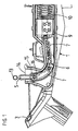
- a pedal device comprises a housing unit 1 and a pedal plate 2, which are hinged together.
- a receptacle 3 for a hinged or flexible connection part 4 connected to the pedal plate 2 is provided in the left end region of the housing unit in FIG. 2.
- the pedal device further comprises a connecting element 5 which is latched to the pedal plate 2 and produces a connection between the pedal plate 2 and further comprising of the pedal device power transmission means 6.
- the power transmission means 6 are designed as a link chain with at least two articulated members 7 (see FIGS. 3a and 3b).
- the power transmission means 6 embodied as a link chain extend through a guide channel 8 of the housing unit 1, which has a curved course, so that the downward force exerted by the pedal plate 2 on the connecting element 5 and the first link 7 of the link chain can be reduced to a position shown in FIG. 2 rightward force is converted, which exerts the right in Fig. 2 member 7 of the link chain on a cylinder 9.
- This cylinder 9 is seated in a corresponding recess of the housing unit 1 and is movable against the force of a spring 10. For example, the movements of the cylinder 9 can be detected with a corresponding sensor.
- a hollow cylinder section-shaped downwardly open locking receptacle 11 is provided on the underside of the pedal plate 2, followed by the side facing away from the pedal plate 2 side guide ribs 12, starting from the locking receptacle 11 and starting from the pedal plate 2 extend away from each other so that a substantially funnel-shaped receptacle for a locking receptacle 11 corresponding provided on the connecting element 5 locking element 13 is formed.
- the latching element 13 is, as can be seen from FIG. 3 a and FIG. 3 b, designed to be substantially cylindrical, so that it can fit snugly into the latching receptacle 11.
- the guide channel 8 terminates, as can be seen in FIGS. 1, 2 and 4, shortly below an upper opening 14 of the housing unit 1, through which the connecting element 5 can protrude outwards in the direction of the pedal plate 2.
- the connecting element 5 projects a little way with an end-side neck 15 into the guide channel 8, wherein at the end of the end-side neck 15, a head 16 is arranged for the articulated connection with the first of the links 7 of the link chain.
- a guide member 17 is attached to the outside of the connecting element 5. From Fig. 3a and Fig. 3b it can be seen that the guide member 17 has a cam-shaped or nose-shaped.
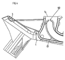
- a lateral recess 18 in the lateral upper end of the guide channel 8 can be seen.
- the recess 18 corresponds in terms of their arrangement and in terms of their shape and size to the guide member 17, so that in the position shown in Fig. 1, the guide member 17 fits into the recess 18.
- the connecting element 5 projects from the upper opening 14 of the housing unit 1 upwards substantially fixed in position. In this way, it can be ensured in an automatic application of the pedal plate 2 on the housing unit 1, that the locking receptacle 11 exactly engages with the locking element 13 of the connecting element 5. This application of the locking receptacle 11 on the locking element 13 is facilitated by the guide ribs 12.
- the counterforce required in the latching is generated, for example, by the spring 10. If the cogging forces are greater than the spring forces, the shape of the guide channel 8 and the shape of the connecting element 5 ensures that internal stops of the connecting element 5 occur in the guide channel 8, so that thereby a counterforce for the latching is generated.
Landscapes
- Engineering & Computer Science (AREA)
- Physics & Mathematics (AREA)
- General Physics & Mathematics (AREA)
- Automation & Control Theory (AREA)
- Chemical & Material Sciences (AREA)
- Combustion & Propulsion (AREA)
- Transportation (AREA)
- Mechanical Engineering (AREA)
- Mechanical Control Devices (AREA)
Description
- Die vorliegende Erfindung betrifft eine Pedalvorrichtung eines Kraftfahrzeugs umfassend eine Pedalplatte, auf die seitens eines Benutzers Kraft ausgeübt werden kann, eine Gehäuseeinheit, an der die Pedalplatte gelenkig befestigt ist, ein Verbindungselement, das mit Kraftübertragungsmitteln im Innern der Gehäuseeinheit verbunden ist und außerhalb der Gehäuseeinheit mit der Pedalplatte verbunden ist.
- Pedalvorrichtungen der vorgenannten Art sind hinlänglich bekannt. Es kann sich bei dem dabei gebildeten Pedal beispielsweise um das Gaspedal eines Kraftfahrzeugs handeln. Die von dem Benutzer ausgeübte Kraft muss über die Kraftübertragungsmittel auf weitere Teile der Pedalvorrichtung übertragen werden. Beispielsweise kann es sich dabei um federabgestützte Teile handeln, deren Bewegung von einem Sensor erfasst werden kann. Die Kraftübertragungsmittel sind in der Regel im Stand der Technik als Gliederketten ausgeführt. Beispielsweise kann hierbei das vorgenannte Verbindungselement das letzte Element einer derartigen Gliederkette sein.
- Als problematisch bei dem vorgenannten Stand der Technik erweist sich, dass eine automatische Montage der Pedalplatte an der Gehäuseeinheit der Pedalvorrichtung nur unter Schwierigkeiten durchführbar ist. Bei dieser automatischen Montage wird nämlich die Gliederkette von der Pedalplatte verdeckt, wobei gleichzeitig sichergestellt werden muss, dass das Verbindungselement sicher mit der Pedalplatte verbunden, beispielsweise verrastet wird. Bei dem Stand der Technik kann das lose Ende des Verbindungselementes eine beliebige Position einnehmen. Gleichzeitig kann aber bei der automatischen Montage der Pedalplatte eine Verbindung, insbesondere eine Verrastung nur dann erfolgen, wenn das Verbindungselement zum Zeitpunkt der Montage der Pedalplatte eine bestimmte Position einnimmt.
- Aus der DE 44 07 005 C1 ist eine Fahrpedaleinrichtung zum Einstellen der Fahrgeschwindigkeit eines Fahrzeuges bekannt, bei der eine Pedalplatte, auf die ein Benutzer eine Kraft ausüben kann, mit einer Gehäuseeinheit verbunden ist. Zur Kraftübertragung ist ein Verbindungselement in Form eine Betätigungsstange vorgesehen, die zwischen der Pedalplatte und der Gehäuseeinheit angeordnet ist.
- Das der vorliegenden Erfindung zugrundeliegende Problem ist somit die Schaffung einer Pedalvorrichtung der eingangs genannten Art, bei der die Pedalplatte vergleichsweise problemlos automatisch an der Gehäuseeinheit montierbar ist.
- Diese wird erfindungsgemäß dadurch erreicht, dass an dem Verbindungselement oder der Gehäuseeinheit ein Führungsteil angebracht ist, und dass in der Gehäuseeinheit oder in dem Verbindungselement eine Ausnehmung vorgesehen ist, in die das Führungsteil eingreift, wodurch die Herstellung der Verbindung des Verbindungselementes mit der Pedalplatte erleichtert wird. Durch das Führungsteil, das in die entsprechende Ausnehmung an der Gehäuseeinheit eingreifen kann, wird gewährleistet, dass zum Zeitpunkt der automatischen Montage der Pedalplatte das Verbindungselement in der für die Verbindung mit der Pedalplatte vorbestimmten Position ist. Dadurch wird die automatische Montage der Pedalplatte ermöglicht.
- Insbesondere kann hierbei die Verbindung zwischen Pedalplatte und Verbindungselement als Rastverbindung ausgeführt sein. Dazu kann an der Unterseite der Pedalplatte eine Rastaufnahme angeordnet sein, in die ein in dem Verbindungselement angeordnetes Rastelement eingreifen kann. Vorteilhafterweise können zusätzlich an der Rastaufnahme sich von dieser und voneinander wegerstreckende Führungsrippen angeordnet sein, die ein Einbringen des Rastelementes in die Rastaufnahme erleichtern. Auf diese Weise wird eine Vorfügung des Verbindungselementes bewirkt, so dass der Einrastvorgang problemlos erfolgen kann.
- Erfindungsgemäß kann vorgesehen sein, dass in der Gehäuseeinheit ein Führungskanal ausgebildet ist, in dem die Kraftübertragungsmittel verlaufen. Hierbei kann die Ausnehmung für die Aufnahme des Führungsteils im Bereich des oberen Endes des Führungskanals angeordnet sein. Durch diese Anordnung der Ausnehmung wird die Positionierung des Verbindungselementes erleichtert.
- Gemäß einer bevorzugten Ausführungsform der vorliegenden Erfindung kann das Führungsteil eine nocken- oder nasenförmige Gestalt aufweisen. Durch eine derartige Gestaltung kann bei entsprechender Ausnehmung mit einfachen baulichen Mitteln eine vergleichsweise sichere Positionierung des Verbindungselementes erzielt werden.
- Insbesondere kann das Führungsteil seitlich an dem Verbindungselement angebracht sein. Auf diese Weise wird gewährleistet, dass das Verbindungselement in die Öffnung des Führungskanals einschiebbar ist bei Druck des Benutzers auf die Pedalplatte, wobei das seitlich angebrachte Führungsteil das Einschieben des Verbindungselementes in den Führungskanal nicht behindert.
- Erfindungsgemäß kann weiterhin vorgesehen sein, dass das Führungsteil im Bereich des von dem Rastelement abgewandten Drittels, insbesondere im Bereich des von dem Rastelement abgewandten Endes des Verbindungselementes angeordnet ist. Auf diese Weise ragt noch ein beträchtlicher Teil des Verbindungselementes aus der Gehäuseeinheit heraus, so dass der Rastvorgang nicht durch die Anordnung des Führungsteils an dem Führungskanal behindert wird.
- Wie bei dem Stand der Technik können auch bei der Erfindung die Kraftübertragungsmittel als Gliederkette ausgebildet sein, wobei das Verbindungselement gelenkig mit einem der Glieder der Kraftübertragungsmittel verbunden ist. Auf diese Weise kann beispielsweise das Verbindungselement das pedalplattenseitig letzte Element der Gliederkette darstellen.
- Weitere Merkmale und Vorteile der vorliegenden Erfindung werden deutlich anhand der nachfolgenden Beschreibung bevorzugter Ausführungsbeispiele unter Bezugnahme auf die beiliegenden Abbildungen. Darin zeigen
- Fig. 1
- eine Seitenansicht einer erfindungsgemäßen Pedalvorrichtung ohne Pedalplatte;
- Fig. 2
- eine Fig. 1 entsprechende geschnittene Darstellung der erfindungsgemäßen Pedalvorrichtung mit aufgebrachter Pedalplatte;
- Fig. 3a
- eine Seitenansicht eines Verbindungselementes mit daran angebrachten Kraftübertragungsmitteln der erfindungsgemäßen Pedalvorrichtung;
- Fig. 3b
- eine Ansicht gemäß dem Pfeil III b in Fig. 3a;
- Fig. 4
- eine der Darstellung gemäß Fig. 1 entsprechende Detailansicht der Gehäuseeinheit der erfindungsgemäßen Pedalvorrichtung ohne Verbindungselement.
- Wie aus Fig. 2 ersichtlich ist umfasst eine erfindungsgemäße Pedalvorrichtung eine Gehäuseeinheit 1 und eine Pedalplatte 2, die gelenkig miteinander verbunden sind. Für diese gelenkige Verbindung ist im in Fig. 2 linken Endbereich der Gehäuseeinheit eine Aufnahme 3 für ein mit der Pedalplatte 2 verbundenes gelenkiges oder flexibles Verbindungsteil 4 vorgesehen.
- Die erfindungsgemäße Pedalvorrichtung umfasst weiterhin ein Verbindungselement 5, das mit der Pedalplatte 2 verrastet ist und eine Verbindung zwischen der Pedalplatte 2 und weiterhin von der Pedalvorrichtung umfassten Kraftübertragungsmitteln 6 herstellt. Die Kraftübertragungsmittel 6 sind als Gliederkette mit zumindest zwei gelenkig miteinander verbundenen Gliedern 7 ausgeführt (siehe dazu Fig. 3a und Fig. 3b). Die als Gliederkette ausgeführten Kraftübertragungsmittel 6 erstrecken sich durch einen Führungskanal 8 der Gehäuseeinheit 1, der einen gebogenen Verlauf aufweist, so dass die von der Pedalplatte 2 auf das Verbindungselement 5 und das erste Glied 7 der Gliederkette ausgeübte nach unten gerichtete Kraft in eine in Fig. 2 nach rechts gerichtete Kraft umgewandelt wird, die das in Fig. 2 rechte Glied 7 der Gliederkette auf einen Zylinder 9 ausübt. Dieser Zylinder 9 sitzt in einer entsprechenden Ausnehmung der Gehäuseeinheit 1 und ist gegen die Kraft einer Feder 10 bewegbar. Beispielsweise können die Bewegungen des Zylinders 9 mit einem entsprechenden Sensor detektiert werden.
- Für die Rastverbindung zwischen Pedalplatte 2 und Verbindungselement 5 ist an der Unterseite der Pedalplatte 2 eine hohlzylinderabschnittsförmige nach unten offene Rastaufnahme 11 vorgesehen, an die sich von der Pedalplatte 2 abgewandten Seite Führungsrippen 12 anschließen, die sich ausgehend von der Rastaufnahme 11 und ausgehend von der Pedalplatte 2 derart voneinander weg erstrecken, dass eine im wesentlichen trichterförmige Aufnahme für ein der Rastaufnahme 11 entsprechendes an dem Verbindungselement 5 vorgesehenes Rastelement 13 entsteht. Das Rastelement 13 ist, wie dies aus Fig. 3a und Fig. 3b ersichtlich ist, im wesentlichen zylindrisch gestaltet, so dass es passend in die Rastaufnahme 11 einrasten kann.
- Der Führungskanal 8 endet, wie dies aus Fig. 1, Fig. 2 und Fig. 4 ersichtlich ist, kurz unterhalb einer oberen Öffnung 14 der Gehäuseeinheit 1, durch die hindurch das Verbindungselement 5 nach außen in Richtung auf die Pedalplatte 2 herausragen kann. Das Verbindungselement 5 ragt ein Stück weit mit einem endseitigen Hals 15 in den Führungskanal 8 hinein, wobei an dem Ende des endseitigen Halses 15 ein Kopf 16 für die gelenkige Verbindung mit dem Ersten der Glieder 7 der Gliederkette angeordnet ist. Im Bereich des Halses 15 ist an der Außenseite des Verbindungselementes 5 ein Führungsteil 17 angebracht. Aus Fig. 3a und Fig. 3b ist ersichtlich, dass das Führungsteil 17 eine nocken- oder nasenförmige Gestalt aufweist.
- Aus Fig. 4 ist eine seitliche Ausnehmung 18 in dem seitlichen oberen Ende des Führungskanals 8 ersichtlich. Die Ausnehmung 18 entspricht hinsichtlich ihrer Anordnung und hinsichtlich ihrer Form und Größe dem Führungsteil 17, so dass in der in Fig. 1 dargestellten Position das Führungsteil 17 passend in die Ausnehmung 18 eingreift.
- In der in Fig. 1 dargestellten Position ragt somit das Verbindungselement 5 im wesentlichen lagefixiert aus der oberen Öffnung 14 der Gehäuseeinheit 1 nach oben heraus. Auf diese Weise kann bei einer automatischen Aufbringung der Pedalplatte 2 auf die Gehäuseeinheit 1 gewährleistet werden, dass die Rastaufnahme 11 exakt in Eingriff mit dem Rastelement 13 des Verbindungselementes 5 gelangt. Diese Aufbringung der Rastaufnahme 11 auf das Rastelement 13 wird durch die Führungsrippen 12 erleichtert. Die bei dem Verrasten notwendige Gegenkraft wird beispielsweise durch die Feder 10 erzeugt. Falls hierbei die Rastkräfte größer sind als die Federkräfte, wird durch die Form des Führungskanals 8 und die Form des Verbindungselementes 5 sichergestellt, dass innere Anschläge des Verbindungselementes 5 in dem Führungskanal 8 auftreten, so dass dadurch eine Gegenkraft für das Verrasten erzeugt wird.
- Erfindungsgemäß besteht die Möglichkeit, das Führungsteil an der Gehäuseeinheit 1 und eine entsprechende Ausnehmung an dem Verbundelement 5 anzuordnen. Mit einer derartigen Umkehrung lassen sich vergleichbare Vorteile erzielen.
-
- 1.
- Gehäuseeinheit
- 2.
- Pedalplatte
- 3.
- Aufnahme für 4
- 4.
- gelenkiges Verbindungsteil zwischen 1 und 2
- 5.
- Verbindungselement
- 6.
- Kraftübertragungsmittel (Gliederkette)
- 7.
- Glieder von 6
- 8.
- Führungskanal
- 9.
- Zylinder
- 10.
- Feder
- 11.
- Rastaufnahme
- 12.
- Führungsrippe
- 13.
- Rastelement an 5
- 14.
- obere Öffnung von 1
- 15.
- Hals an 5
- 16.
- Kopf an 15
- 17.
- Führungsteil an 5
- 18.
- Ausnehmung für 17
Claims (10)
- Pedalvorrichtung eines Kraftfahrzeugs umfassend- eine Pedalplatte (2), auf die seitens eines Benutzers Kraft ausgeübt werden kann,- eine Gehäuseeinheit (1), an der die Pedalplatte (2) gelenkig befestigt ist,- ein Verbindungselement (5), das mit Kraftübertragungsmitteln (6) im Innern der Gehäuseeinheit (1) verbunden ist und außerhalb der Gehäuseeinheit (1) mit der Pedalplatte (2) verbunden ist,dadurch gekennzeichnet, dass- an dem Verbindungselement (5) oder an der Gehäuseeinheit (1) ein Führungsteil (17) angebracht ist, und dass- in der Gehäuseeinheit (1) oder in dem Verbindungselement (5) eine Ausnehmung (18) vorgesehen ist, in die das Führungsteil (17) eingreift,- wodurch die Herstellung der Verbindung des Verbindungselementes (5) mit der Pedalplatte (2) erleichtert wird.
- Pedalvorrichtung nach Anspruch 1, dadurch gekennzeichnet, dass die Verbindung zwischen Pedalplatte (2) und Verbindungselement (5) als Rastverbindung ausgeführt ist.
- Pedalvorrichtung nach Anspruch 2, dadurch gekennzeichnet, dass an der Unterseite der Pedalplatte (2) eine Rastaufnahme (11) angeordnet ist, in die ein an dem Verbindungselement (5) angeordnetes Rastelement (13) eingreifen kann.
- Pedalvorrichtung nach Anspruch 3, dadurch gekennzeichnet, dass an der Rastaufnahme (11) sich von dieser und voneinander wegerstreckende Führungsrippen (12) angeordnet sind, die ein Einbringen des Rastelementes (13) in die Rastaufnahme (11) erleichtern.
- Pedalvorrichtung nach einem der Ansprüche 1 bis 4, dadurch gekennzeichnet, dass in der Gehäuseeinheit (1) ein Führungskanal (8) ausgebildet ist, in dem die Kraftübertragungsmittel (6) verlaufen.
- Pedalvorrichtung nach Anspruch 5, dadurch gekennzeichnet, dass die Ausnehmung (18) für die Aufnahme des Führungsteils (17) im Bereich des oberen Endes des Führungskanals (8) angeordnet ist.
- Pedalvorrichtung nach einem der Ansprüche 1 bis 6, dadurch gekennzeichnet, dass das Führungsteil (17) eine nocken- oder nasenförmige Gestalt aufweist.
- Pedalvorrichtung nach einem der Ansprüche 1 bis 7, dadurch gekennzeichnet, dass das Führungsteil (17) seitlich an dem Verbindungselement (5) angebracht ist.
- Pedalvorrichtung nach einem der Ansprüche 1 bis 8, dadurch gekennzeichnet, dass das Führungsteil (17) im Bereich des von dem Rastelement (13) abgewandten Drittels, insbesondere im Bereich des von dem Rastelement (13) abgewandten Endes des Verbindungselementes (5) angeordnet ist.
- Pedalvorrichtung nach einem der Ansprüche 1 bis 9, dadurch gekennzeichnet, dass die Kraftübertragungsmittel (6) als Gliederkette ausgebildet sind, wobei das Verbindungselement (5) gelenkig mit einem der Glieder (7) der Kraftübertragungsmittel (6) verbunden ist.
Applications Claiming Priority (2)
| Application Number | Priority Date | Filing Date | Title |
|---|---|---|---|
| DE10236358 | 2002-08-08 | ||
| DE2002136358 DE10236358A1 (de) | 2002-08-08 | 2002-08-08 | Pedalvorrichtung eines Kraftfahrzeugs |
Publications (2)
| Publication Number | Publication Date |
|---|---|
| EP1388455A1 EP1388455A1 (de) | 2004-02-11 |
| EP1388455B1 true EP1388455B1 (de) | 2006-03-22 |
Family
ID=30128775
Family Applications (1)
| Application Number | Title | Priority Date | Filing Date |
|---|---|---|---|
| EP20030102438 Expired - Lifetime EP1388455B1 (de) | 2002-08-08 | 2003-08-06 | Pedalvorrichtung eines Kraftfahrzeugs |
Country Status (3)
| Country | Link |
|---|---|
| EP (1) | EP1388455B1 (de) |
| DE (2) | DE10236358A1 (de) |
| ES (1) | ES2258698T3 (de) |
Families Citing this family (4)
| Publication number | Priority date | Publication date | Assignee | Title |
|---|---|---|---|---|
| DE102006035882B4 (de) * | 2006-07-31 | 2008-05-29 | MÄNNLE, Erik | Pedalanordnung mit einem stehenden Pedal |
| JP4433007B2 (ja) | 2007-07-10 | 2010-03-17 | 株式会社デンソー | 回転角検出装置 |
| DE202008017713U1 (de) * | 2008-08-30 | 2010-04-29 | MÄNNLE, Erik | Pedalanordnung mit einem um eine horizontale Achse schwenkbaren stehenden Pedal |
| US12157367B1 (en) * | 2023-06-23 | 2024-12-03 | GM Global Technology Operations LLC | Adjustable pedal system |
Family Cites Families (7)
| Publication number | Priority date | Publication date | Assignee | Title |
|---|---|---|---|---|
| SE443671B (sv) * | 1984-07-16 | 1986-03-03 | Leif Conny Rost | Pedalanordning |
| US5666860A (en) * | 1993-12-21 | 1997-09-16 | Dr. Ing. H.C.F. Porsche Ag | Gas pedal arrangement for a motor vehicle |
| DE4407005C1 (de) * | 1994-03-03 | 1995-03-09 | Hella Kg Hueck & Co | Fahrpedaleinrichtung |
| GB2295352A (en) * | 1994-11-26 | 1996-05-29 | Ford Motor Co | A pedal |
| DE29519852U1 (de) * | 1995-12-14 | 1996-02-01 | Vofa-Werk Xavier Vorbrüggen GmbH & Co KG, 40549 Düsseldorf | Pedaleinrichtung |
| DE19814765A1 (de) * | 1998-04-02 | 1999-10-07 | Porsche Ag | Gaspedaleinrichtung für ein Kraftfahrzeug |
| DE10133194A1 (de) * | 2001-07-07 | 2003-01-16 | Hella Kg Hueck & Co | Fahrpedaleinrichtung zum Einstellen der Fahrgeschwindigkeit eines Fahrzeuges |
-
2002
- 2002-08-08 DE DE2002136358 patent/DE10236358A1/de not_active Withdrawn
-
2003
- 2003-08-06 ES ES03102438T patent/ES2258698T3/es not_active Expired - Lifetime
- 2003-08-06 EP EP20030102438 patent/EP1388455B1/de not_active Expired - Lifetime
- 2003-08-06 DE DE50302732T patent/DE50302732D1/de not_active Expired - Lifetime
Also Published As
| Publication number | Publication date |
|---|---|
| EP1388455A1 (de) | 2004-02-11 |
| DE10236358A1 (de) | 2004-02-19 |
| DE50302732D1 (de) | 2006-05-11 |
| ES2258698T3 (es) | 2006-09-01 |
Similar Documents
| Publication | Publication Date | Title |
|---|---|---|
| DE102012213992B4 (de) | Luftklappenvorrichtung mit gesondertem Lagerbauteil zur vereinfachten Montage | |
| DE112020000008T5 (de) | Bündig versenkbarer Griff für eine Fahrzeugtür | |
| WO2008061836A1 (de) | Elektromechanische antriebsvorrichtung zum einsatz in einer heckklappe eines kraftfahrzeugs | |
| DE60015473T2 (de) | Verbinder | |
| EP3405997A1 (de) | Elektrischer steckverbinder und verfahren zu dessen montage | |
| DE60020179T3 (de) | Türgriff für Kraftfahrzeug | |
| DE19914598B4 (de) | Montageanordnung und Stellglied für ein Fenster mit elektrischem Scheibenheber | |
| EP3700023B1 (de) | Steckverbindergehäuse und steckverbindung | |
| DE202013101929U1 (de) | Zugentlastungsgehäuse | |
| DE10336254A1 (de) | Verbinder und Verbinderanordnung | |
| WO2021254821A1 (de) | Modularer steckverbinder | |
| EP0806317A1 (de) | Tankklappe mit integrierter Aufspringmechanik | |
| DE102020100367B4 (de) | Signalkommunikationssteckdose | |
| DE102018102706A1 (de) | Leiteranschlussklemme, Betätigungswerkzeug und Set daraus | |
| EP2949842B1 (de) | Türgriffanordnung für ein kraftfahrzeug | |
| DE19651436A1 (de) | Vorrichtung zum Verbinden von elektrischen Kontakten | |
| EP1388455A1 (de) | Pedalvorrichtung eines Kraftfahrzeugs | |
| DE102007035641B3 (de) | Übertragungssystem | |
| DE102005033621A1 (de) | Vorrichtung mit einer Dichtungstülle für einen Leitungsübergang zwischen relativ zueinander bewegbaren Fahrzeugteilen | |
| EP2466117A1 (de) | Startvorrichtung für einen Brennkraftmotor | |
| DE102020202346A1 (de) | Verbindungsvorrichtung für kabel | |
| EP1489712B1 (de) | Zugentlastung für ein Elektrokabel | |
| DE102011056659A1 (de) | Schraubklemmanschluss-Vorrichtung | |
| DE20205665U1 (de) | Verbindungsklemme zum Anschluß und Abgriff von elektrischen Leitern | |
| DE202005005241U1 (de) | Schwerer elektrischer Steckverbinder mit Verriegelungsklammern |
Legal Events
| Date | Code | Title | Description |
|---|---|---|---|
| PUAI | Public reference made under article 153(3) epc to a published international application that has entered the european phase |
Free format text: ORIGINAL CODE: 0009012 |
|
| AK | Designated contracting states |
Kind code of ref document: A1 Designated state(s): AT BE BG CH CY CZ DE DK EE ES FI FR GB GR HU IE IT LI LU MC NL PT RO SE SI SK TR |
|
| AX | Request for extension of the european patent |
Extension state: AL LT LV MK |
|
| 17P | Request for examination filed |
Effective date: 20040730 |
|
| AKX | Designation fees paid |
Designated state(s): DE ES FR GB IT SE |
|
| RAP1 | Party data changed (applicant data changed or rights of an application transferred) |
Owner name: HELLA KGAA HUECK & CO. |
|
| 17Q | First examination report despatched |
Effective date: 20050221 |
|
| GRAP | Despatch of communication of intention to grant a patent |
Free format text: ORIGINAL CODE: EPIDOSNIGR1 |
|
| GRAS | Grant fee paid |
Free format text: ORIGINAL CODE: EPIDOSNIGR3 |
|
| GRAA | (expected) grant |
Free format text: ORIGINAL CODE: 0009210 |
|
| AK | Designated contracting states |
Kind code of ref document: B1 Designated state(s): DE ES FR GB IT SE |
|
| REG | Reference to a national code |
Ref country code: GB Ref legal event code: FG4D Free format text: NOT ENGLISH |
|
| REG | Reference to a national code |
Ref country code: SE Ref legal event code: TRGR |
|
| REF | Corresponds to: |
Ref document number: 50302732 Country of ref document: DE Date of ref document: 20060511 Kind code of ref document: P |
|
| GBT | Gb: translation of ep patent filed (gb section 77(6)(a)/1977) |
Effective date: 20060505 |
|
| PGFP | Annual fee paid to national office [announced via postgrant information from national office to epo] |
Ref country code: FR Payment date: 20060808 Year of fee payment: 4 |
|
| PGFP | Annual fee paid to national office [announced via postgrant information from national office to epo] |
Ref country code: IT Payment date: 20060831 Year of fee payment: 4 |
|
| REG | Reference to a national code |
Ref country code: ES Ref legal event code: FG2A Ref document number: 2258698 Country of ref document: ES Kind code of ref document: T3 |
|
| PGFP | Annual fee paid to national office [announced via postgrant information from national office to epo] |
Ref country code: ES Payment date: 20060921 Year of fee payment: 4 |
|
| ET | Fr: translation filed | ||
| PLBE | No opposition filed within time limit |
Free format text: ORIGINAL CODE: 0009261 |
|
| STAA | Information on the status of an ep patent application or granted ep patent |
Free format text: STATUS: NO OPPOSITION FILED WITHIN TIME LIMIT |
|
| 26N | No opposition filed |
Effective date: 20061227 |
|
| PGFP | Annual fee paid to national office [announced via postgrant information from national office to epo] |
Ref country code: SE Payment date: 20060804 Year of fee payment: 4 |
|
| EUG | Se: european patent has lapsed | ||
| GBPC | Gb: european patent ceased through non-payment of renewal fee |
Effective date: 20070806 |
|
| PG25 | Lapsed in a contracting state [announced via postgrant information from national office to epo] |
Ref country code: SE Free format text: LAPSE BECAUSE OF NON-PAYMENT OF DUE FEES Effective date: 20070807 |
|
| REG | Reference to a national code |
Ref country code: FR Ref legal event code: ST Effective date: 20080430 |
|
| PG25 | Lapsed in a contracting state [announced via postgrant information from national office to epo] |
Ref country code: FR Free format text: LAPSE BECAUSE OF NON-PAYMENT OF DUE FEES Effective date: 20070831 |
|
| REG | Reference to a national code |
Ref country code: ES Ref legal event code: FD2A Effective date: 20070807 |
|
| PG25 | Lapsed in a contracting state [announced via postgrant information from national office to epo] |
Ref country code: GB Free format text: LAPSE BECAUSE OF NON-PAYMENT OF DUE FEES Effective date: 20070806 |
|
| PG25 | Lapsed in a contracting state [announced via postgrant information from national office to epo] |
Ref country code: ES Free format text: LAPSE BECAUSE OF NON-PAYMENT OF DUE FEES Effective date: 20070807 |
|
| PG25 | Lapsed in a contracting state [announced via postgrant information from national office to epo] |
Ref country code: IT Free format text: LAPSE BECAUSE OF NON-PAYMENT OF DUE FEES Effective date: 20070806 |
|
| REG | Reference to a national code |
Ref country code: DE Ref legal event code: R084 Ref document number: 50302732 Country of ref document: DE |
|
| REG | Reference to a national code |
Ref country code: DE Ref legal event code: R084 Ref document number: 50302732 Country of ref document: DE Effective date: 20111028 |
|
| PGFP | Annual fee paid to national office [announced via postgrant information from national office to epo] |
Ref country code: DE Payment date: 20170801 Year of fee payment: 15 |
|
| REG | Reference to a national code |
Ref country code: DE Ref legal event code: R081 Ref document number: 50302732 Country of ref document: DE Owner name: HELLA GMBH CO. KGAA, DE Free format text: FORMER OWNER: HELLA KGAA HUECK CO., 59557 LIPPSTADT, DE Ref country code: DE Ref legal event code: R081 Ref document number: 50302732 Country of ref document: DE Owner name: HELLA GMBH & CO. KGAA, DE Free format text: FORMER OWNER: HELLA KGAA HUECK & CO., 59557 LIPPSTADT, DE |
|
| REG | Reference to a national code |
Ref country code: DE Ref legal event code: R119 Ref document number: 50302732 Country of ref document: DE |
|
| PG25 | Lapsed in a contracting state [announced via postgrant information from national office to epo] |
Ref country code: DE Free format text: LAPSE BECAUSE OF NON-PAYMENT OF DUE FEES Effective date: 20190301 |