EP1387973B1 - Ventilantrieb - Google Patents
Ventilantrieb Download PDFInfo
- Publication number
- EP1387973B1 EP1387973B1 EP02727864A EP02727864A EP1387973B1 EP 1387973 B1 EP1387973 B1 EP 1387973B1 EP 02727864 A EP02727864 A EP 02727864A EP 02727864 A EP02727864 A EP 02727864A EP 1387973 B1 EP1387973 B1 EP 1387973B1
- Authority
- EP
- European Patent Office
- Prior art keywords
- ring
- valve actuator
- actuator according
- housing
- valve
- Prior art date
- Legal status (The legal status is an assumption and is not a legal conclusion. Google has not performed a legal analysis and makes no representation as to the accuracy of the status listed.)
- Expired - Lifetime
Links
- 230000008878 coupling Effects 0.000 claims description 10
- 238000010168 coupling process Methods 0.000 claims description 10
- 238000005859 coupling reaction Methods 0.000 claims description 10
- 230000002265 prevention Effects 0.000 claims description 3
- 230000001419 dependent effect Effects 0.000 abstract 1
- 238000006073 displacement reaction Methods 0.000 description 4
- 230000002093 peripheral effect Effects 0.000 description 3
- 238000013459 approach Methods 0.000 description 2
- 230000000694 effects Effects 0.000 description 2
- 238000010438 heat treatment Methods 0.000 description 2
- 239000007788 liquid Substances 0.000 description 2
- 230000006978 adaptation Effects 0.000 description 1
- 230000008602 contraction Effects 0.000 description 1
- 230000007423 decrease Effects 0.000 description 1
- 238000013461 design Methods 0.000 description 1
- 230000000763 evoking effect Effects 0.000 description 1
- 230000005484 gravity Effects 0.000 description 1
- 230000013011 mating Effects 0.000 description 1
- 238000000034 method Methods 0.000 description 1
- 238000012549 training Methods 0.000 description 1
- 238000013519 translation Methods 0.000 description 1
Images


Classifications
-
- F—MECHANICAL ENGINEERING; LIGHTING; HEATING; WEAPONS; BLASTING
- F16—ENGINEERING ELEMENTS AND UNITS; GENERAL MEASURES FOR PRODUCING AND MAINTAINING EFFECTIVE FUNCTIONING OF MACHINES OR INSTALLATIONS; THERMAL INSULATION IN GENERAL
- F16K—VALVES; TAPS; COCKS; ACTUATING-FLOATS; DEVICES FOR VENTING OR AERATING
- F16K31/00—Actuating devices; Operating means; Releasing devices
- F16K31/02—Actuating devices; Operating means; Releasing devices electric; magnetic
- F16K31/04—Actuating devices; Operating means; Releasing devices electric; magnetic using a motor
- F16K31/046—Actuating devices; Operating means; Releasing devices electric; magnetic using a motor with electric means, e.g. electric switches, to control the motor or to control a clutch between the valve and the motor
-
- F—MECHANICAL ENGINEERING; LIGHTING; HEATING; WEAPONS; BLASTING
- F16—ENGINEERING ELEMENTS AND UNITS; GENERAL MEASURES FOR PRODUCING AND MAINTAINING EFFECTIVE FUNCTIONING OF MACHINES OR INSTALLATIONS; THERMAL INSULATION IN GENERAL
- F16K—VALVES; TAPS; COCKS; ACTUATING-FLOATS; DEVICES FOR VENTING OR AERATING
- F16K31/00—Actuating devices; Operating means; Releasing devices
- F16K31/02—Actuating devices; Operating means; Releasing devices electric; magnetic
- F16K31/04—Actuating devices; Operating means; Releasing devices electric; magnetic using a motor
- F16K31/047—Actuating devices; Operating means; Releasing devices electric; magnetic using a motor characterised by mechanical means between the motor and the valve, e.g. lost motion means reducing backlash, clutches, brakes or return means
Definitions
- the invention relates to a valve drive with a Housing and a motor.
- valve drive which is known from EP 0 380 787, is used to To control opening degree of a valve.
- valves come in particular liquid valves for liquid control of air heating systems, as for the heating of tents, halls or halls be used. These valves usually have a closure member cooperating with a valve seat.
- the closing element is in many cases in Opening direction with a spring (or another Force).
- the valve drive must therefore only generate a force to close the valve.
- the Opening the valve is controlled by the Spindle to which the valve element is connected, more or less far out.
- the invention will therefore be the For simplicity, by biased in the opening direction Valves described. She is in the corresponding Way also biased in the closing direction Valves applicable.
- the invention is based on the object, a valve drive automatically adapt to different valves.
- This valve drive does not monitor the stroke the valve spindle. One controls only, if one Load on the actuating rod acts or not. It is assumed that the opening spring of Valve causes a load on the actuating rod, as long as the operating rod on the valve stem press with a force greater than one predetermined threshold. If now the closing element of the valve in its maximum open position it can not move any further. When the actuating rod of the valve drive on the other hand moved further in the opening direction, then lifts it off the valve stem. In this take off, but at the latest after taking off the operating rod no longer loaded by the valve spindle. This load drop is from the load sensor detected by the fact that the valve his maximum open position has taken.
- the load sensor is coupled to a control device, which shuts off the engine due to this signal.
- the shutdown can be limited to that the motor stops turning in the opening direction. A drive in the opposite direction, however, would be still possible.
- the end of load is always recognized regardless of the length of the stroke.
- the valve actuator can therefore practically without changes be used with different valves.
- the load sensor has a switch on, actuated by an actuator assembly is, via a clutch detachable with the drive part is connected, wherein the switching state of the coupling of the axial position of the drive member relative to the Housing depends.
- actuating rod upon actuation of the valve protrudes down from the drive part. If so the actuating rod through the opening spring of the valve is loaded, then the operating rod is slightly raised and with it the drive part. Thereby when the clutch is released, i. open. The Actuator assembly is released from the drive part. If however, the operating rod far enough in the drive part she has been pushed in, then she will no longer supported by the valve stem.
- the drive part is designed as a nut, screwed onto a thread on the actuator rod is.
- This embodiment has several advantages. On the one hand can be with the help of such a screw drive achieve a relatively large translation, so that the engine are dimensioned relatively weak can. But above all, it is important that the operating rod and the nut in the axial direction, i. in the direction of movement the operating rod, practically rigid coupled together so that a movement of the Actuating rod transferred directly to the mother that will be directly on the clutch again can work.
- the clutch a displaceable relative to the drive part Ring with an actuating attachment and an internal toothing which is in an operating position with an external toothing on the drive part in engagement can be brought.
- the drive part can thus be the clutch and move out, where the shift depends on the burden situation.
- the coupling thus forms a Part of the load sensor.
- the ring is displaceable in the radial direction and the internal toothing is at a predetermined peripheral portion limited.
- the ring is in the radial direction, ie perpendicular to the axis of the drive part, moves is, then is only a relatively small movement necessary to disengage the internal teeth the external teeth on the drive part to bring.
- the Displacement movement can therefore affect the depth of the restrict both gears.
- the ring disengaged is, then the external teeth on the drive part Although in contact with the inner wall of the ring stand.
- Friction that is insufficient to ring the clutch take.
- the ring has a wedge-shaped cam on, which in a rotation of the ring in a corresponding adapted wedge-shaped groove engages in the housing. So if the ring is turned, comes the wedge-shaped cams after a predetermined angle of rotation in engagement with the wedge-shaped groove. At another Rotational movement of the ring is the cam through the corresponding edge of the groove literally in the radial direction pulled out. Because the cam is attached to the ring is, the ring follows the cam, so that the ring in the radial direction is relocated. This movement comes the internal teeth on the ring out of engagement with the external teeth on the drive part.
- a Return spring arranged, which turns the ring towards loaded the engaged position. If now the ring again is turned in the other direction, which generates Return spring the restoring force that is necessary again engagement between the ring and the drive part to effect.
- This return spring can be relative be weak. It's enough if you has a relatively small lay length. It only has to to be able to relocate the ring so far that an engagement between the internal teeth on the ring and the external teeth on the drive part again is set up.
- the restoring prevention device by a respective friction surface on Ring and is formed on the housing.
- the friction between These two areas are enough to reset to prevent.
- the prerequisite for this, of course, is that the return spring is adapted accordingly.
- the clutch a spreadable ring with an actuating attachment on, with a toothing on the drive part in not spread state is engaged. If the ring is spread, so at least a partial increase in diameter has experienced, then comes the gearing on the drive part and a corresponding toothing on Ring out of engagement. When the drive part, for example the mother turns, then the ring turns not with. If necessary, one can ensure that the ring in the spread state by a smaller one or greater friction force held in the housing becomes. If, however, the spread canceled, then come the gearing engaged with each other and the Ring then rotates together with the drive part.
- the actuation attachment something stands out from the ring, so that he is able to operate a switch.
- the actuator can be integral with the ring be educated. Its length and size depends among other things depending on where the switch is positioned and as he is trained.
- the ring has a slot.
- the Slit the ring becomes compliant, i. he lets himself widen or spread more easily.
- the ring has an internal toothing on, which extends over a part of its inner circumference.
- Such shortened gearing is sufficient to take the ring when closing the clutch and subsequently to operate the switch.
- An im otherwise smooth inner peripheral wall of the ring reduces the Risk of accidental misoperation of the ring he follows.
- the ring is provided with a ring spring. So you do not rely on the inherent elasticity anymore of the ring, but supports the contraction of the ring through the ring spring.
- the ring has an inner cone, which cooperates with a spreading arrangement in the housing.
- This is a relatively simple way to axial movement implement the ring in the spreading process. If the ring with its inner cone against the spreading arrangement is pressed, then widens the ring, so that its toothing with that of the drive part except Intervention comes. If, however, the inner cone of the Spreizanix is deducted, then the ring can contract again and engage accordingly with the drive part.
- the spreading arrangement has an outer cone on.
- the inner cone and the outer cone are particularly effective good and gentle together, so that a long life is guaranteed.
- the outer cone is on a pipe end face arranged.
- a tube can easily in Housing to be mounted. It allows free access on the screwed onto the operating rod nut.
- a valve drive 1 serves a schematic, Dashed valve 2 to control, i. one To move closing element 3 on a valve seat 4 and to close, or the valve element 3 from the valve seat 4 and thus open.
- the closing movement is limited by the fact that the closing element. 3 abuts the valve seat 4.
- An opening movement is thereby limited that the closing element 3 on a housing 5 or against another stop.
- Fig. 1 the maximum open position of the valve 2 is shown.
- the movement of the closing element 3 is controlled by a valve stem 6, by a spring 7 in the opening direction is preloaded.
- the spring 7 is supported on the housing 5.
- the valve drive 1 has an actuating rod, which, based on the illustration of FIG. 1, upward and is movable downwards.
- the closing element 3 When the operating rod 8 is moved down and in contact with the valve stem 6 comes, then the closing element 3 at further movement of the actuating rod 8 on the valve seat 4 to move.
- the operating rod 8 after is moved above then follows the valve stem 6 of Actuating rod 8 until the closing element. 3 rests against the housing 5.
- the actuating rod 8 in turn is driven by a nut 9, which has a gear 10-12 of a motor 13 (partially by the operating rod 8 hidden) is driven.
- the engine 13 displaces the Mother 9 in rotary motion.
- the operating rod 8 is rotatably held, so that the rotational movement of the Nut 9 via a thread 14 in a translatory Movement of the actuating rod 8 converts.
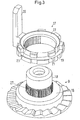
- the nut 9 has an increase in diameter 15, which forms a bearing surface 16 on which a ring 17th rests.
- the ring 17 surrounds a portion 18 of the Mother.
- the ring has, as can be seen from Fig. 2 is a slot 19 and an actuating attachment 20th on.
- the ring has an inner cone 22. On his inner wall the ring has an internal toothing 23 which but only over a part of the inner circumference extends.
- a tube 25 is arranged, that is an outer cone 26 on its front side having.
- This outer cone 26 interacts with the inner cone 22 of the ring 17 together. If the ring 17 on this Outside cone 26 is pushed, then spreads the Outer cone 26, the ring 17 against the force of the annular spring 21 on. If you do not use the ring 17 against the Outer cone 26 presses, then the ring is under the effect the annular spring 21 contracted again.
- the nut 9 has at the portion 18 above the Support surface 16 an outer toothing 27, which with the internal toothing 23 of the ring 17 engages, when the ring 17 is not spread. In this case the ring 17 is taken with a rotation of the nut 9.
- the actuation attachment 20 then comes after one small turn into engagement with a switch 28 and press this.
- the switch 28 is not one connected control device, the due to the operation of the switch 28, the motor 13th shuts down.
- the valve drive 1 now works as follows:
- the motor 13 is thus always stopped when the Closing element 3 is assumed its maximum opening position regardless of how big the stroke overall is. It is therefore possible, the valve drive at different valves with different stroke paths without complicated adaptation measures required are.
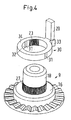
- Fig. 4 shows a modified embodiment of a Coupling, in the same parts with the same reference numerals are provided as in the design of FIG. 3rd Has changed mainly the ring 30.
- the ring 30 now no longer has a slot. He is rather closed trained. He has one of the circular shape deviating form. More precisely, he is elongated formed, which symbolizes in Fig. 4 thereby is that he has extension sections between two halves of the circle 31 has.
- the internal toothing 23 is at a predetermined peripheral portion limited on the inside 32. Of the The remaining area of the inside 32 is smooth.
- a wedge-shaped cam 33 is provided, in connection will be explained with Fig. 5.
- the inner diameter of the ring 30 in the longitudinal direction is sufficient for a corresponding displacement movement of the ring 30 relative to the nut 9, which is substantially takes place parallel to the support surface 16, the Internal toothing 23 out of engagement with the external toothing 27 to come to the mother 9.
- the inner diameter in the direction transverse to the greatest longitudinal extent can be approximately the outer diameter of the mother. 9 in the outer toothing 27 correspond.
- the ring 30 has on its axial top one Pressure surface 34, which at a corresponding axial Pressurization (in the present case from below) on a corresponding mating surface (not closer shown) in the housing comes to rest.
- the printing surface 34 and the counter surface in the housing then form a Friction, to overcome a predetermined Force is required.
- Fig. 5 shows now various operating positions of Coupling of Fig. 4.
- the nut 9 is shown as a continuous bolt.
- the operating rod 8 can be screwed.
- Fig. 5a illustrates a situation in which the ring 30th upon rotation of the nut 9 in the clockwise direction is taken.
- the wedge-shaped cam 33 comes in engagement with a corresponding wedge-shaped groove 36 on the housing 5, more precisely with a wedge-shaped Flank 37 of this groove 36.
- the wedge-shaped edge 37 acts with a corresponding counter flank on the wedge-shaped Cam 33 together so that the ring 30 radially something is shifted, as shown in Fig. 5b is.
- the internal teeth 23 on the ring 30 comes with it out of engagement with the external teeth 27 on the nut 9. This displacement movement takes place against the force a return spring 35, which, however, relatively weak is trained.
- Fig. 5c now shows the situation where the nut 9 in the opposite direction is turned.
- the ring 30 can be taken something.
- the groove 36 points but a boundary edge 38, which is another Rotation of the ring 30 prevents.
- the switch 28 is So still not pressed.
Landscapes
- Engineering & Computer Science (AREA)
- General Engineering & Computer Science (AREA)
- Mechanical Engineering (AREA)
- Mechanically-Actuated Valves (AREA)
- Hydraulic Clutches, Magnetic Clutches, Fluid Clutches, And Fluid Joints (AREA)
- Magnetically Actuated Valves (AREA)
- Valve-Gear Or Valve Arrangements (AREA)
- Valve Device For Special Equipments (AREA)
- Electrically Driven Valve-Operating Means (AREA)
Applications Claiming Priority (3)
| Application Number | Priority Date | Filing Date | Title |
|---|---|---|---|
| DE10123706 | 2001-05-15 | ||
| DE10123706A DE10123706B4 (de) | 2001-05-15 | 2001-05-15 | Ventilantrieb |
| PCT/IB2002/001602 WO2002095276A1 (de) | 2001-05-15 | 2002-05-10 | Ventilantrieb |
Publications (2)
| Publication Number | Publication Date |
|---|---|
| EP1387973A1 EP1387973A1 (de) | 2004-02-11 |
| EP1387973B1 true EP1387973B1 (de) | 2005-02-16 |
Family
ID=7684925
Family Applications (1)
| Application Number | Title | Priority Date | Filing Date |
|---|---|---|---|
| EP02727864A Expired - Lifetime EP1387973B1 (de) | 2001-05-15 | 2002-05-10 | Ventilantrieb |
Country Status (7)
| Country | Link |
|---|---|
| EP (1) | EP1387973B1 (pl) |
| CN (1) | CN1509384A (pl) |
| AT (1) | ATE289394T1 (pl) |
| DE (1) | DE10123706B4 (pl) |
| PL (1) | PL364075A1 (pl) |
| RU (1) | RU2003136755A (pl) |
| WO (1) | WO2002095276A1 (pl) |
Families Citing this family (1)
| Publication number | Priority date | Publication date | Assignee | Title |
|---|---|---|---|---|
| JP6557921B2 (ja) * | 2015-04-27 | 2019-08-14 | 株式会社テージーケー | 電動弁装置および電動弁制御装置 |
Family Cites Families (4)
| Publication number | Priority date | Publication date | Assignee | Title |
|---|---|---|---|---|
| US4063707A (en) * | 1976-01-23 | 1977-12-20 | Philadelphia Gear Corporation | Valve protective mechanism for power operated valves |
| DE3703478A1 (de) * | 1986-06-02 | 1987-12-03 | Siemens Ag | Doppeltwirkender drehantrieb fuer ein stellorgan |
| US4898362A (en) * | 1989-01-31 | 1990-02-06 | Liberty Technology Center, Inc. | Thrust actuated control for motor operated valve |
| US5090239A (en) * | 1991-01-18 | 1992-02-25 | Teledyne Industries, Inc. | Strain sensing valve |
-
2001
- 2001-05-15 DE DE10123706A patent/DE10123706B4/de not_active Expired - Fee Related
-
2002
- 2002-05-10 EP EP02727864A patent/EP1387973B1/de not_active Expired - Lifetime
- 2002-05-10 PL PL02364075A patent/PL364075A1/pl unknown
- 2002-05-10 WO PCT/IB2002/001602 patent/WO2002095276A1/de not_active Ceased
- 2002-05-10 CN CNA02810126XA patent/CN1509384A/zh active Pending
- 2002-05-10 RU RU2003136755/06A patent/RU2003136755A/ru not_active Application Discontinuation
- 2002-05-10 AT AT02727864T patent/ATE289394T1/de not_active IP Right Cessation
Also Published As
| Publication number | Publication date |
|---|---|
| CN1509384A (zh) | 2004-06-30 |
| RU2003136755A (ru) | 2005-05-20 |
| EP1387973A1 (de) | 2004-02-11 |
| ATE289394T1 (de) | 2005-03-15 |
| PL364075A1 (pl) | 2004-12-13 |
| WO2002095276A1 (de) | 2002-11-28 |
| DE10123706A1 (de) | 2002-12-05 |
| DE10123706B4 (de) | 2004-11-11 |
Similar Documents
| Publication | Publication Date | Title |
|---|---|---|
| DE2303618B2 (de) | Vorrichtung zum Nachstellen von Reibungskupplungen | |
| DE202008002265U1 (de) | Vorrichtung zum Aufweiten von Rohren | |
| EP3361017B1 (de) | Befestigungsvorrichtung | |
| EP0348854A2 (de) | Steuervorrichtung für mindestens ein Ventil | |
| EP3372315B1 (de) | Schwenkbrause mit absperrventil | |
| DE2733083C3 (pl) | ||
| EP2891826A2 (de) | Elektromotorischer Linearantrieb | |
| DE2813841C2 (pl) | ||
| DE1425206B2 (de) | Selbsttätige mechanische Nachstellvorrichtung für druckmittelbetätigte Gestänge einer Reibungskupplung oder Bremse | |
| DE60020917T2 (de) | Betätigungseinrichtung einer Entkupplungsvorrichtung für einen Getriebemotorantrieb einer Schliess- oder Sonnenschutzeinrichtung | |
| EP1387973B1 (de) | Ventilantrieb | |
| DE10027598B4 (de) | Ventil | |
| DE2554284C2 (de) | Schnellschluß-Sicherheitshahn mit in einem Gehäuse gelagerten Kugelküken | |
| DE2521315C3 (de) | Hydraulische Überlastkupplung, insbesondere für Förderer- und Hobelantriebe u.dgl | |
| DE10123705C2 (de) | Ventilantrieb | |
| DE202014100217U1 (de) | Gargerät | |
| DE102014005628A1 (de) | Armaturen-Schaltvorrichtung und Armaturen-Stellanordnung | |
| DE102006016666A1 (de) | Vorrichtung zur Betätigung einer Kupplung | |
| DE602004004696T2 (de) | Getriebe mit einer Schneckenwelle für Rolladen | |
| EP0178599B1 (de) | Stellventil, insbesondere Drosselventil | |
| DE2723043C3 (pl) | ||
| EP0266594A1 (de) | Kugelhahn | |
| DE102010054391A1 (de) | Schaltvorrichtung für Stellantriebe, insbesondere zur Ansteuerung von Ventilklappen | |
| DE19543543C2 (de) | Katheterventil | |
| DE102004049796B4 (de) | Linearantrieb |
Legal Events
| Date | Code | Title | Description |
|---|---|---|---|
| PUAI | Public reference made under article 153(3) epc to a published international application that has entered the european phase |
Free format text: ORIGINAL CODE: 0009012 |
|
| 17P | Request for examination filed |
Effective date: 20031030 |
|
| AK | Designated contracting states |
Kind code of ref document: A1 Designated state(s): AT BE CH CY DE DK ES FI FR GB GR IE IT LI LU MC NL PT SE TR |
|
| AX | Request for extension of the european patent |
Extension state: AL LT LV MK RO SI |
|
| GRAP | Despatch of communication of intention to grant a patent |
Free format text: ORIGINAL CODE: EPIDOSNIGR1 |
|
| GRAS | Grant fee paid |
Free format text: ORIGINAL CODE: EPIDOSNIGR3 |
|
| GRAA | (expected) grant |
Free format text: ORIGINAL CODE: 0009210 |
|
| RBV | Designated contracting states (corrected) |
Designated state(s): AT BE CH CY DK ES FI FR GB GR IE IT LI LU MC NL PT SE TR |
|
| AK | Designated contracting states |
Kind code of ref document: B1 Designated state(s): AT BE CH CY DK ES FI FR GB GR IE IT LI LU MC NL PT SE TR |
|
| PG25 | Lapsed in a contracting state [announced via postgrant information from national office to epo] |
Ref country code: FI Free format text: LAPSE BECAUSE OF FAILURE TO SUBMIT A TRANSLATION OF THE DESCRIPTION OR TO PAY THE FEE WITHIN THE PRESCRIBED TIME-LIMIT Effective date: 20050216 Ref country code: NL Free format text: LAPSE BECAUSE OF FAILURE TO SUBMIT A TRANSLATION OF THE DESCRIPTION OR TO PAY THE FEE WITHIN THE PRESCRIBED TIME-LIMIT Effective date: 20050216 Ref country code: TR Free format text: LAPSE BECAUSE OF FAILURE TO SUBMIT A TRANSLATION OF THE DESCRIPTION OR TO PAY THE FEE WITHIN THE PRESCRIBED TIME-LIMIT Effective date: 20050216 Ref country code: IE Free format text: LAPSE BECAUSE OF FAILURE TO SUBMIT A TRANSLATION OF THE DESCRIPTION OR TO PAY THE FEE WITHIN THE PRESCRIBED TIME-LIMIT Effective date: 20050216 |
|
| REG | Reference to a national code |
Ref country code: GB Ref legal event code: FG4D Free format text: NOT ENGLISH |
|
| REG | Reference to a national code |
Ref country code: CH Ref legal event code: EP |
|
| REG | Reference to a national code |
Ref country code: DE Ref legal event code: 8566 |
|
| REG | Reference to a national code |
Ref country code: IE Ref legal event code: FG4D Free format text: GERMAN |
|
| PG25 | Lapsed in a contracting state [announced via postgrant information from national office to epo] |
Ref country code: LU Free format text: LAPSE BECAUSE OF NON-PAYMENT OF DUE FEES Effective date: 20050510 Ref country code: AT Free format text: LAPSE BECAUSE OF NON-PAYMENT OF DUE FEES Effective date: 20050510 Ref country code: CY Free format text: LAPSE BECAUSE OF FAILURE TO SUBMIT A TRANSLATION OF THE DESCRIPTION OR TO PAY THE FEE WITHIN THE PRESCRIBED TIME-LIMIT Effective date: 20050510 |
|
| REG | Reference to a national code |
Ref country code: CH Ref legal event code: NV Representative=s name: LUCHS & PARTNER PATENTANWAELTE |
|
| PG25 | Lapsed in a contracting state [announced via postgrant information from national office to epo] |
Ref country code: SE Free format text: LAPSE BECAUSE OF FAILURE TO SUBMIT A TRANSLATION OF THE DESCRIPTION OR TO PAY THE FEE WITHIN THE PRESCRIBED TIME-LIMIT Effective date: 20050516 Ref country code: DK Free format text: LAPSE BECAUSE OF FAILURE TO SUBMIT A TRANSLATION OF THE DESCRIPTION OR TO PAY THE FEE WITHIN THE PRESCRIBED TIME-LIMIT Effective date: 20050516 Ref country code: GR Free format text: LAPSE BECAUSE OF FAILURE TO SUBMIT A TRANSLATION OF THE DESCRIPTION OR TO PAY THE FEE WITHIN THE PRESCRIBED TIME-LIMIT Effective date: 20050516 |
|
| PG25 | Lapsed in a contracting state [announced via postgrant information from national office to epo] |
Ref country code: ES Free format text: LAPSE BECAUSE OF FAILURE TO SUBMIT A TRANSLATION OF THE DESCRIPTION OR TO PAY THE FEE WITHIN THE PRESCRIBED TIME-LIMIT Effective date: 20050527 |
|
| PG25 | Lapsed in a contracting state [announced via postgrant information from national office to epo] |
Ref country code: MC Free format text: LAPSE BECAUSE OF NON-PAYMENT OF DUE FEES Effective date: 20050531 Ref country code: BE Free format text: LAPSE BECAUSE OF NON-PAYMENT OF DUE FEES Effective date: 20050531 |
|
| GBT | Gb: translation of ep patent filed (gb section 77(6)(a)/1977) |
Effective date: 20050516 |
|
| NLV1 | Nl: lapsed or annulled due to failure to fulfill the requirements of art. 29p and 29m of the patents act | ||
| PG25 | Lapsed in a contracting state [announced via postgrant information from national office to epo] |
Ref country code: PT Free format text: LAPSE BECAUSE OF FAILURE TO SUBMIT A TRANSLATION OF THE DESCRIPTION OR TO PAY THE FEE WITHIN THE PRESCRIBED TIME-LIMIT Effective date: 20050804 |
|
| REG | Reference to a national code |
Ref country code: IE Ref legal event code: FD4D |
|
| BERE | Be: lapsed |
Owner name: DANFOSS TRATA D.O.O. Effective date: 20050531 |
|
| PLBE | No opposition filed within time limit |
Free format text: ORIGINAL CODE: 0009261 |
|
| STAA | Information on the status of an ep patent application or granted ep patent |
Free format text: STATUS: NO OPPOSITION FILED WITHIN TIME LIMIT |
|
| ET | Fr: translation filed | ||
| 26N | No opposition filed |
Effective date: 20051117 |
|
| PGFP | Annual fee paid to national office [announced via postgrant information from national office to epo] |
Ref country code: CH Payment date: 20070516 Year of fee payment: 6 |
|
| PGFP | Annual fee paid to national office [announced via postgrant information from national office to epo] |
Ref country code: GB Payment date: 20070509 Year of fee payment: 6 |
|
| BERE | Be: lapsed |
Owner name: DANFOSS TRATA D.O.O. Effective date: 20050531 |
|
| PGFP | Annual fee paid to national office [announced via postgrant information from national office to epo] |
Ref country code: IT Payment date: 20070507 Year of fee payment: 6 |
|
| PGFP | Annual fee paid to national office [announced via postgrant information from national office to epo] |
Ref country code: FR Payment date: 20070510 Year of fee payment: 6 |
|
| REG | Reference to a national code |
Ref country code: CH Ref legal event code: PL |
|
| GBPC | Gb: european patent ceased through non-payment of renewal fee |
Effective date: 20080510 |
|
| PG25 | Lapsed in a contracting state [announced via postgrant information from national office to epo] |
Ref country code: LI Free format text: LAPSE BECAUSE OF NON-PAYMENT OF DUE FEES Effective date: 20080531 Ref country code: CH Free format text: LAPSE BECAUSE OF NON-PAYMENT OF DUE FEES Effective date: 20080531 |
|
| REG | Reference to a national code |
Ref country code: FR Ref legal event code: ST Effective date: 20090119 |
|
| PG25 | Lapsed in a contracting state [announced via postgrant information from national office to epo] |
Ref country code: FR Free format text: LAPSE BECAUSE OF NON-PAYMENT OF DUE FEES Effective date: 20080602 |
|
| PG25 | Lapsed in a contracting state [announced via postgrant information from national office to epo] |
Ref country code: GB Free format text: LAPSE BECAUSE OF NON-PAYMENT OF DUE FEES Effective date: 20080510 |
|
| PG25 | Lapsed in a contracting state [announced via postgrant information from national office to epo] |
Ref country code: IT Free format text: LAPSE BECAUSE OF NON-PAYMENT OF DUE FEES Effective date: 20080510 |