EP1386825A2 - Lenkanlage für Mobilfahrzeuge - Google Patents
Lenkanlage für Mobilfahrzeuge Download PDFInfo
- Publication number
- EP1386825A2 EP1386825A2 EP03016950A EP03016950A EP1386825A2 EP 1386825 A2 EP1386825 A2 EP 1386825A2 EP 03016950 A EP03016950 A EP 03016950A EP 03016950 A EP03016950 A EP 03016950A EP 1386825 A2 EP1386825 A2 EP 1386825A2
- Authority
- EP
- European Patent Office
- Prior art keywords
- steering
- steering system
- circuit
- steering actuator
- actuator
- Prior art date
- Legal status (The legal status is an assumption and is not a legal conclusion. Google has not performed a legal analysis and makes no representation as to the accuracy of the status listed.)
- Withdrawn
Links
Images
Classifications
-
- B—PERFORMING OPERATIONS; TRANSPORTING
- B62—LAND VEHICLES FOR TRAVELLING OTHERWISE THAN ON RAILS
- B62D—MOTOR VEHICLES; TRAILERS
- B62D5/00—Power-assisted or power-driven steering
- B62D5/06—Power-assisted or power-driven steering fluid, i.e. using a pressurised fluid for most or all the force required for steering a vehicle
- B62D5/30—Safety devices, e.g. alternate emergency power supply or transmission means to ensure steering upon failure of the primary steering means
-
- B—PERFORMING OPERATIONS; TRANSPORTING
- B62—LAND VEHICLES FOR TRAVELLING OTHERWISE THAN ON RAILS
- B62D—MOTOR VEHICLES; TRAILERS
- B62D5/00—Power-assisted or power-driven steering
- B62D5/04—Power-assisted or power-driven steering electrical, e.g. using an electric servo-motor connected to, or forming part of, the steering gear
- B62D5/0403—Power-assisted or power-driven steering electrical, e.g. using an electric servo-motor connected to, or forming part of, the steering gear characterised by constructional features, e.g. common housing for motor and gear box
- B62D5/0406—Power-assisted or power-driven steering electrical, e.g. using an electric servo-motor connected to, or forming part of, the steering gear characterised by constructional features, e.g. common housing for motor and gear box including housing for electronic control unit
-
- B—PERFORMING OPERATIONS; TRANSPORTING
- B62—LAND VEHICLES FOR TRAVELLING OTHERWISE THAN ON RAILS
- B62D—MOTOR VEHICLES; TRAILERS
- B62D5/00—Power-assisted or power-driven steering
- B62D5/04—Power-assisted or power-driven steering electrical, e.g. using an electric servo-motor connected to, or forming part of, the steering gear
- B62D5/0421—Electric motor acting on or near steering gear
- B62D5/0424—Electric motor acting on or near steering gear the axes of motor and final driven element of steering gear, e.g. rack, being parallel
-
- B—PERFORMING OPERATIONS; TRANSPORTING
- B62—LAND VEHICLES FOR TRAVELLING OTHERWISE THAN ON RAILS
- B62D—MOTOR VEHICLES; TRAILERS
- B62D5/00—Power-assisted or power-driven steering
- B62D5/06—Power-assisted or power-driven steering fluid, i.e. using a pressurised fluid for most or all the force required for steering a vehicle
- B62D5/10—Power-assisted or power-driven steering fluid, i.e. using a pressurised fluid for most or all the force required for steering a vehicle characterised by type of power unit
- B62D5/12—Piston and cylinder
Definitions
- the invention relates to a steering system for mobile vehicles, in particular vehicles for agricultural use, with the features of the preamble of claim 1.
- a two-circuit steering system is known from DE 199 10 001 for mobile vehicles, in particular vehicles for agricultural use, with a first, hydrostatic Steering circuit with a double-acting pressure medium cylinder, the one with an axle bridge housing and on its two Ends connected to steerable wheel hubs via tie rods is and a second steering circuit with an electric Steering actuator.
- the electric steering actuator is over the tie rods and a piston rod of the double-acting pressure medium cylinder connected to the steerable wheel hubs.
- the double-acting pressure cylinder is at this stand the technology in front of the axle and the electric steering actuator provided behind the axle.
- a disadvantage of this stand The technology is that the large steering angle in vehicles for agricultural use and the necessary large displacement paths of the actuators to a high space requirement guide and with the described installation of the electric steering actuator is difficult to implement.
- the electric steering actuator and its supply lines are through their exposed positions are insufficient from damage protected by obstacles.
- the electric steering actuator must be constructed so that it is in addition to the occurring Steering forces also carries its own weight, the to initiate the large steering forces acting spatially necessary joint elements between the electric steering actuator and the wheel hub or axle are very large. It is with This state of the art also two steering units with corresponding articulation points on the wheel hub and axle as well increased number of components and the associated to apply increased assembly effort.
- the object of the invention is to provide a steering system for mobile vehicles, especially agricultural vehicles Use to create with the disadvantages of the stand of technology are eliminated.
- a steering system for mobile vehicles in particular vehicles for agricultural use, with a first, for example a hydrostatic, Steering circuit with a double-acting pressure medium cylinder, the one with an axle housing and at both ends is connected to steerable wheel hubs via tie rods and a second steering circuit, for example with a electric steering actuator.
- the hydrostatic Steering circuit can also be used as a second and the electric steering circuit be provided as the first steering circuit.
- the electric actuated steering actuator is in front of, below, above or mounted behind on the pressure cylinder and with a Coupling element equipped to transmit the actuating movements of the electrically operated steering actuator on a piston rod of the hydrostatic steering circuit.
- the pressure cylinder and the electrically operated Steering controller housed in a common housing, the is preferably variably mountable on different axes, so that the assembly effort is reduced according to the invention.
- control and power electronics for the electrically operated steering actuator in the common housing accommodated.
Landscapes
- Engineering & Computer Science (AREA)
- Chemical & Material Sciences (AREA)
- Combustion & Propulsion (AREA)
- Transportation (AREA)
- Mechanical Engineering (AREA)
- Steering-Linkage Mechanisms And Four-Wheel Steering (AREA)
- Power Steering Mechanism (AREA)
Abstract
Description
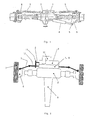
Es zeigen:
- Fig. 1
- eine Lenkanlage an einer angetriebenen Achse des Standes der Technik und
- Fig. 2
- eine schematisch dargestellte Lenkanlage an einer angetriebenen Achse gemäß der Erfindung.
- Fig. 1: Eine Lenkanlage des Standes der Technik eines Fahrzeugs (nicht dargestellt) für landwirtschaftlichen Einsatz weist einen ersten, hydrostatischen Lenkkreis mit einem doppelt wirkenden Druckmittelzylinder 1 auf, der vor einem Achsbrückengehäuse 2 montiert ist und an seinen beiden Enden über Spurstangen 3 und je ein Gelenkgehäuse 6 mit lenkbaren Radnaben 7 verbunden ist. Ein zweiter Lenkkreis mit einem elektrischen Lenksteller 4 ist dem Druckmittelzylinder 1 gegenüberliegend hinter dem Achsbrückengehäuse 2 montiert und über ein Kugelgelenk 5 an ein Gelenkgehäuse 6 einer lenkbaren Radnabe 7 gebunden.
- Fig. 2: Eine fremdkraftbetätigbare Lenkanlage eines Fahrzeugs (nicht dargestellt) für landwirtschaftlichen Einsatz weist einen ersten, hydrostatischen Lenkkreis mit einem doppelt wirkenden Druckmittelzylinder 1 in einem Gehäuse 8 auf, der vor einem Achsgehäuse 2 mit Schubrohr 9 montiert ist. Ein zweiter Lenkkreis mit einem von einem elektrischen Motor 10 betätigten elektrischen Lenksteller 4 ist ebenfalls in dem Gehäuse 8 an dem Druckmittelzylinder 1 vor dem Achsgehäuse 2 montiert und über eine Kolbenstange 13 und ein Koppelelement 11 mit der Kolbenstange 12 des Druckmittelzylinders 1 verbunden. Die Kolbenstange 12 ist an ihren beiden Enden über Spurstangen 3 und je ein Gelenkgehäuse 6 mit den lenkbaren Rädern 7 verbunden.Die Verkabelung und/oder Verrohrung (nicht dargestellt) ist zentral mit der Steuerung und Leistungselektronik (nicht dargestellt) für den elektrisch betätigten Lenksteller 4 in dem gemeinsamen Gehäuse 8 untergebracht.
- 1
- Druckmittelzylinder
- 2
- Achsgehäuse
- 3
- Spurstange
- 4
- elektrischer Lenksteller
- 5
- Kugelgelenk
- 6
- Gelenkgehäuse
- 7
- Rad (nabe)
- 8
- Gehäuse
- 9
- Schubrohr
- 10
- elektrischer Motor
- 11
- Koppelelement
- 12
- Kolbenstange
- 13
- Kolbenstange
Claims (5)
- Lenkanlage für Mobilfahrzeuge, insbesondere Fahrzeuge für landwirtschaftlichen Einsatz, mit einem ersten, beispielsweise einem hydrostatischen, Lenkkreis mit einem doppelt wirkenden Druckmittelzylinder (1), der mit einem Achsgehäuse (2) und an seinen beiden Enden über Spurstangen (3) mit lenkbaren Radnaben (7) verbunden ist und einem zweiten Lenkkreis, beispielsweise mit einem elektrischen Lenksteller (4), dadurch gekennzeichnet, dass der elektrisch betätigbare Lenksteller (4) parallel vor, unter, über oder hinten an dem Druckmittelzylinder (1) montiert ist und mit einem Koppelelement (11) ausgestattet ist zur Übertragung der Stellbewegungen des elektrisch betätigten Lenkstellers (4) auf eine Kolbenstange (12) des hydrostatischen Lenkkreises.
- Lenkanlage gemäß Anspruch 1, dadurch gekennzeichnet, dass der Druckmittelzylinder (1) und der elektrisch betätigte Lenksteller (4) in einem gemeinsamen Gehäuse (8) untergebracht sind.
- Lenkanlage gemäß Anspruch 3, dadurch gekennzeichnet, dass das gemeinsame Gehäuse (8) variabel montierbar an verschiedenen Achsen (2) ist.
- Lenkanlage gemäß Anspruch 3, dadurch gekennzeichnet , dass an dem gemeinsamen Gehäuse (8) die Verkabelung und/oder Verrohrung zentral angebracht ist.
- Lenkanlage gemäß Anspruch 3, dadurch gekennzeichnet, dass Steuerung und Leistungselektronik für den elektrisch betätigten Lenksteller (4) in dem gemeinsamen Gehäuse (8) untergebracht sind.
Applications Claiming Priority (2)
| Application Number | Priority Date | Filing Date | Title |
|---|---|---|---|
| DE2002135107 DE10235107A1 (de) | 2002-08-01 | 2002-08-01 | Lenkanlage für Mobilfahrzeuge |
| DE10235107 | 2002-08-01 |
Publications (2)
| Publication Number | Publication Date |
|---|---|
| EP1386825A2 true EP1386825A2 (de) | 2004-02-04 |
| EP1386825A3 EP1386825A3 (de) | 2007-05-02 |
Family
ID=30010545
Family Applications (1)
| Application Number | Title | Priority Date | Filing Date |
|---|---|---|---|
| EP03016950A Withdrawn EP1386825A3 (de) | 2002-08-01 | 2003-07-25 | Lenkanlage für Mobilfahrzeuge |
Country Status (2)
| Country | Link |
|---|---|
| EP (1) | EP1386825A3 (de) |
| DE (1) | DE10235107A1 (de) |
Cited By (4)
| Publication number | Priority date | Publication date | Assignee | Title |
|---|---|---|---|---|
| NL1033771C2 (nl) * | 2007-04-27 | 2008-10-28 | Transp Industry Dev Ct Bv | Stuurinrichting. |
| WO2010041926A1 (en) * | 2008-10-10 | 2010-04-15 | Transport Industry Development Centre B.V. | Steering system |
| ITMO20100143A1 (it) * | 2010-05-12 | 2011-11-13 | Ivan Borghi | Gruppo di sterzatura per ruote di veicoli |
| EP2248708A3 (de) * | 2009-05-08 | 2017-03-29 | ZF Friedrichshafen AG | Lenkbare Fahrzeugachse |
Families Citing this family (1)
| Publication number | Priority date | Publication date | Assignee | Title |
|---|---|---|---|---|
| DE102012207005A1 (de) | 2012-04-27 | 2013-10-31 | Schaeffler Technologies AG & Co. KG | Elektromechanische Fahrzeuglenkung |
Family Cites Families (6)
| Publication number | Priority date | Publication date | Assignee | Title |
|---|---|---|---|---|
| JPH0447025Y2 (de) * | 1986-04-23 | 1992-11-06 | ||
| DE19603568C2 (de) * | 1996-02-01 | 1998-03-26 | Daimler Benz Ag | Lenkung für Kraftfahrzeuge |
| DE19910001B4 (de) * | 1999-03-08 | 2008-04-17 | Zf Friedrichshafen Ag | Zweikreis-Lenkanlage für Mobilfahrzeuge |
| DE19918225A1 (de) * | 1999-04-22 | 2000-11-02 | Daimler Chrysler Ag | Randwinkelsteller |
| DE10023584A1 (de) * | 2000-05-13 | 2001-11-15 | Bosch Gmbh Robert | Verbesserte Anordnung des Drehmomentsensors bzw. des Hydroventils einer servo-unterstützten Lenkung mit Stellglied für Kraftfahrzeuge |
| DE10048697A1 (de) * | 2000-09-30 | 2002-04-18 | Bosch Gmbh Robert | Steer-by-Wire-Lenkanlage mit Zahnstangen-Hydrolenksteller |
-
2002
- 2002-08-01 DE DE2002135107 patent/DE10235107A1/de not_active Withdrawn
-
2003
- 2003-07-25 EP EP03016950A patent/EP1386825A3/de not_active Withdrawn
Cited By (6)
| Publication number | Priority date | Publication date | Assignee | Title |
|---|---|---|---|---|
| NL1033771C2 (nl) * | 2007-04-27 | 2008-10-28 | Transp Industry Dev Ct Bv | Stuurinrichting. |
| EP1985525A1 (de) * | 2007-04-27 | 2008-10-29 | Transport Industry Development Centre B.V. | Lenksystem |
| WO2010041926A1 (en) * | 2008-10-10 | 2010-04-15 | Transport Industry Development Centre B.V. | Steering system |
| EP2248708A3 (de) * | 2009-05-08 | 2017-03-29 | ZF Friedrichshafen AG | Lenkbare Fahrzeugachse |
| ITMO20100143A1 (it) * | 2010-05-12 | 2011-11-13 | Ivan Borghi | Gruppo di sterzatura per ruote di veicoli |
| WO2011141794A3 (en) * | 2010-05-12 | 2012-01-05 | Ivan Borghi | Steering unit for vehicle wheels |
Also Published As
| Publication number | Publication date |
|---|---|
| EP1386825A3 (de) | 2007-05-02 |
| DE10235107A1 (de) | 2004-02-19 |
Similar Documents
| Publication | Publication Date | Title |
|---|---|---|
| DE102013200388A1 (de) | Antrieb für ein Flurförderzeug mit Lenkunterstützung | |
| EP3437961B1 (de) | Hydraulisches lenksystem | |
| DE2948181C2 (de) | Vorrichtung zur Steuerung der Lenkbarkeit einer selbstlenkenden Schlepp- oder Vorlaufachse | |
| DE2451743A1 (de) | Verkehrsleiteinrichtung | |
| DE19727289A1 (de) | Einsatzfahrzeug, insbesondere Feuerwehrfahrzeug, für den Straßen- und Schienenbetrieb | |
| DE102014009036A1 (de) | Transportfahrzeug, insbesondere selbstangetriebenes Transportfahrzeug, mit variabler Breite | |
| DE10300513A1 (de) | Kutsche | |
| DE10235107A1 (de) | Lenkanlage für Mobilfahrzeuge | |
| EP2920105B1 (de) | Lenksystem für ein flurförderzeug | |
| DE102023134396A1 (de) | Radaufhängung für ein Fahrzeug und Fahrzeug mit einer Radaufhängung | |
| DE602005002020T2 (de) | Lenkachse für fahrzeuge, insbesondere für arbeitsmaschinen oder ackerschlepper | |
| DE102018201808A1 (de) | Achsenanordnung und Fahrzeug | |
| DE202014005055U1 (de) | Transportfahrzeug, insbesondere selbstangetriebenes Transportfahrzeug, mit variabler Breite | |
| EP3649038B1 (de) | Verstelleinrichtung für ein fahrwerk eines kraftfahrzeuges sowie hinterachslenkung | |
| DE102019007492A1 (de) | Verstellvorrichtung für eine Umgebungserfassungseinrichtung eines Kraftfahrzeugs sowie Verfahren | |
| EP3315382B1 (de) | Lenksystem für ein kraftfahrzeug, vorzugsweise ein fahrschul-kraftfahrzeug | |
| DE202011108878U1 (de) | Hinterachslenkvorrichtung für Anhängefahrzeuge, insbesondere für Schneidwerkswagen | |
| DE102018116617A1 (de) | Lenkradeinheit mit Positionierungssystem für ein elektromechanisches Lenksystem | |
| WO1989001435A1 (fr) | Vehicule special avec direction et cabine du conducteur pouvant etre abaissee | |
| EP1243497B1 (de) | Kraftfahrzeug mit mindestens einer Hinter-Achse mit lenkbaren Hinterrädern | |
| EP0544086A2 (de) | Hydraulische Hilfskraft-Lenkeinrichtung für Kraftfahrzeuge | |
| DE2752570B2 (de) | Lenkvorrichtung für Kraftfahrzeuge | |
| AT395572B (de) | Hydrostatische lenkanlage | |
| EP4190673B1 (de) | Fahrzeugachse und deren anordnung an einem fahrzeug | |
| DE202019001615U1 (de) | Schneidwerkswagen |
Legal Events
| Date | Code | Title | Description |
|---|---|---|---|
| PUAI | Public reference made under article 153(3) epc to a published international application that has entered the european phase |
Free format text: ORIGINAL CODE: 0009012 |
|
| AK | Designated contracting states |
Kind code of ref document: A2 Designated state(s): AT BE BG CH CY CZ DE DK EE ES FI FR GB GR HU IE IT LI LU MC NL PT RO SE SI SK TR |
|
| AX | Request for extension of the european patent |
Extension state: AL LT LV MK |
|
| PUAL | Search report despatched |
Free format text: ORIGINAL CODE: 0009013 |
|
| AK | Designated contracting states |
Kind code of ref document: A3 Designated state(s): AT BE BG CH CY CZ DE DK EE ES FI FR GB GR HU IE IT LI LU MC NL PT RO SE SI SK TR |
|
| AX | Request for extension of the european patent |
Extension state: AL LT LV MK |
|
| AKX | Designation fees paid | ||
| STAA | Information on the status of an ep patent application or granted ep patent |
Free format text: STATUS: THE APPLICATION IS DEEMED TO BE WITHDRAWN |
|
| 18D | Application deemed to be withdrawn |
Effective date: 20071103 |
|
| REG | Reference to a national code |
Ref country code: DE Ref legal event code: 8566 |