EP1386575A1 - Geschirrspülmaschine mit durch den Spülwasserstrom rotierbarer Filter- und Zerkleinerungsvorrichtung - Google Patents
Geschirrspülmaschine mit durch den Spülwasserstrom rotierbarer Filter- und Zerkleinerungsvorrichtung Download PDFInfo
- Publication number
- EP1386575A1 EP1386575A1 EP02425497A EP02425497A EP1386575A1 EP 1386575 A1 EP1386575 A1 EP 1386575A1 EP 02425497 A EP02425497 A EP 02425497A EP 02425497 A EP02425497 A EP 02425497A EP 1386575 A1 EP1386575 A1 EP 1386575A1
- Authority
- EP
- European Patent Office
- Prior art keywords
- sump
- microfilter
- dishwashing machine
- machine according
- filter
- Prior art date
- Legal status (The legal status is an assumption and is not a legal conclusion. Google has not performed a legal analysis and makes no representation as to the accuracy of the status listed.)
- Granted
Links
Images
Classifications
-
- A—HUMAN NECESSITIES
- A47—FURNITURE; DOMESTIC ARTICLES OR APPLIANCES; COFFEE MILLS; SPICE MILLS; SUCTION CLEANERS IN GENERAL
- A47L—DOMESTIC WASHING OR CLEANING; SUCTION CLEANERS IN GENERAL
- A47L15/00—Washing or rinsing machines for crockery or tableware
- A47L15/42—Details
- A47L15/4202—Water filter means or strainers
- A47L15/4206—Tubular filters
-
- A—HUMAN NECESSITIES
- A47—FURNITURE; DOMESTIC ARTICLES OR APPLIANCES; COFFEE MILLS; SPICE MILLS; SUCTION CLEANERS IN GENERAL
- A47L—DOMESTIC WASHING OR CLEANING; SUCTION CLEANERS IN GENERAL
- A47L15/00—Washing or rinsing machines for crockery or tableware
- A47L15/42—Details
- A47L15/4214—Water supply, recirculation or discharge arrangements; Devices therefor
- A47L15/4225—Arrangements or adaption of recirculation or discharge pumps
- A47L15/4227—Arrangements or adaption of recirculation or discharge pumps with macerator arrangements for chopping entrained food particles
Definitions
- This invention pertains to a dishwashing machine with macerator filter caused to rotate by the wash liquid flow.
- the first requirement is to have reduced consumption of water and detergent, hence of heating power, in the hot washing stages.
- the water used in the different stages of a washing cycle (that may include, in this sequence, subsequent stages of prewash, wash, 1 st rinse, 2 nd rinse) is recirculated.
- the washing tub is filled with a given volume of liquid, generally ranging 1 to 1.5 litres, next the latter is conveyed by a pump to one or several spray arms placed in the wash chamber.
- the jets flowing out of the arms spray all over the dishes, the water falls within the tub, and is collected in a pan or sump. From there it is sucked out again by the recirculation pump.
- the volume of water used in each stage cannot be less than a given amount: actually, it must be ensured that the recirculation circuit is filled up completely (this circuit has a remarkable capacity, mainly due to the collection pan size) in order to prevent pump cavitation.
- Water recirculation permits to remove by dish spraying the food soil present on them.
- it calls for use of filters, to prevent soil from being recirculated as well. This might damage the recirculation pump and re-soil the dishes .
- Two cascaded filters are generally used: one large-meshed, retaining the larger sized (>1-2 mm)food soil particles, the other one fine-meshed, the so-called microfilter, retaining the finer particles (ranging 0.2 to 0.3 mm).
- the large-meshed filter if appropriate connected with a small filter-basin, makes up the top closure of the collection sump, whereas the microfilter is housed inside the sump, upstream the recirculation pump.
- Both the large-meshed filter and the microfilter are removable for hand cleaning, even if, as we will see, microfilter self-cleaning systems have been developed.
- microfilter fitted within the recirculation circuit produces considerable loss of pressure and it can even get clogged. This may block or significantly limit the recirculation flow.
- the most frequently adopted solution provides for splitting the recirculation flow: only part of the flow passes through the microfilter, the rest is directly sucked by the recirculation pump, only passing through the large-meshed filter.
- the vortex produced in the liquid causes - at least in theory - the filter to rotate.
- This invention solves all the above mentioned problems and provides for a dishwashing machine with extremely reduced volumetric capacity of the recirculation circuit, removable microfilter automatically cleaned in counterflow to the recirculation flow and caused to rotate by the recirculation flow throughout the duration of the washing and rinsing stages, so to evenly distribute the soil deposit onto the microfilter.
- the torque acting onto the filter is large enough to enable the latter to macerate and emulsify the soil particles passing through the large-meshed filter; the soil particle size is thus considerably reduced.
- the particles, reduced in size, once retained by the microfilter, are less likely to develop lumps and can be more easily detached from the filter meshes and kept in suspension in the liquid that is drained, without forming films, specially fat ones, adhering to the walls.
- Reduction in particle size also involves reduction in particle size distribution provoked by the different density of the suspended particles, and hence the agglomeration of several particles of the same type.
- Maceration ultimately has a synergetic effect on the use of a microfilter, in that it promotes self-cleaning, calling for less mechanical action to remove soil particles from the filter.
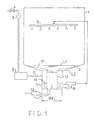
- Figure 1 shows a schematic overall drawing of a dishwashing machine that, except the special features that will be stated, can be regarded as known art, such as for instance the one disclosed in IT-1,197,983 and EP-752,231.
- the machine includes a wash chamber 1 ending at the bottom with a tub 2 extending below to form a collection sump 3, generally of a cylindrical form, with diameter ⁇ B ranging 100-120 mm and depth ranging 80-100 mm.
- a given volume of water (approx. 1,2-1,5 litres) is admitted into the sump through an inlet valve 4, an air jump separator 5, required to comply with safety regulations, a resin water softener 6, and a supply pipe 7. This water fills the sump and the washing tub up to a L1 level.
- a large-meshed filtering plate 11 is placed in tub 2, the former aimed at separating collection sump from the wash chamber.
- the filtering plate 11 can be equipped, at the sump, of a recess in the form of a basin, generally removable, in which the coarser fraction of the solid residues settle down.
- a fine-meshed filter 12 or microfilter generally of a cylindrical form, housed in sump 3.
- This microfilter divides the sump volume in a center cylindrical section, and in a cylindrical annular crown.
- the recirculation flow passing through filtering plate 11 partly enters the annular crown and partly flows into the center cylindrical section. Next it is sucked by the suction pump.
- microfilter 12 The liquid entering the central section and sucked by the pump passes through microfilter 12 from the inside to the outside and undergoes an additional filtration, whereas the liquid entering the circular crown is not further filtered, and conveys in itself the finest solid particles. However, during the subsequent recirculation this liquid as well, mixed with that further filtered, ends up passing through the microfilter, so that the whole recirculation flow is filtered by the microfilter, onto the wall of which the finest soil particles are deposited.
- the coarsest particles, if present, are collected in the basin of filtering plate 11.
- the clean water jet from pipe 7 is adequately oriented in order to hit the filtering wall.
- the filter is rotably mounted within the sump, and is caused to rotate by same spraying jet. Accordingly, the whole filtering wall is sprayed and passed through in countercurrent by the jet.
- drain pump 10 Even when drain pump 10 is not operative, to fill the internal volume of microfilter, the liquid present into the sump must pass through it in countercurrent, thus it tends to remove soil from the microfilter and to place it in suspension.
- a rotably supported filter also provides an additional benefit: whenever during a washing cycle the filter may take a shifted position, different from the subsequent stages of the cycle, a more even distribution of the soil particles on the filtering wall can be achieved.
- Patent EP-752,231 proposes to exploit the vortex induced within sump 3 by the recirculation flow suctioned through an orifice placed tangent to the circumferential wall of the sump.
- the action of the vortex proves inadequate to consistently produce this effect. Also, for the vortex to be produced, it is required to make use of a suitably sized sump, that increases the volumetric capacity of the recirculation circuit, calling for a larger volume of supply water and hence larger consumption.
- this invention provides substantial enhancement: it cannot be denied that besides a possible vortex effect there is, in the sump, an axial flow from the top to the bottom, with an average speed determined by the flow rate of the recirculation pump and by the sump cross-section.
- the pump flow rate typically ranges 80 to 120 litres/minute.
- the value of 90 litres/minute equal to 1.5 l/s.
- the average rate of the axial flow provoked by the recirculation pump is approximately equal to 0.15 m/s, provided that the diameter ⁇ B of the sump is equal to 120 mm. Nevertheless, it increases to approximately 0.3 m/s if diameter ⁇ B is reduced to 80 mm, and even to over 0.5 m/s if the diameter is reduced to 60 mm.
- the axial flow mainly concentrates in the annular crown outside the filter, it is clear that - even with a sump diameter equal to 80 mm and a microfilter diameter indicatively equal to 60 mm, the axial velocity of the flow in the annular crown must range 0.3 m/s to 0.54 m/s and the closer to the upper limit, the larger the microfilter resistance to passing through it.
- the average axial velocity of the flow into the annular crown is approximately equal to 0.4 m/s. This value increases, besides with the degree of microfilter clogging, along the axial direction of the sump, from the top to the bottom, except in the bottom area where the suction orifice opens up, where the average axial velocity becomes less meaningful, and where incidentally the average speed of the suctioned flow is much larger and is a function of the suction orifice diameter.
- microfilter rotation is ensured.
- the rotating microfilter can also act as an emulsifying food soil macerator.
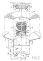
- FIG. 2 an exploded perspective view, partly in diametral section, relevant to the concerned machine components only, identified by the same number references already used in Fig.1 shows a preferred embodiment of the invention 1.
- the washing tub in the shape of a large tapered funnel, develops at its bottom section in a cylindrical sump 3, with smaller diameter than the conventional one, preferably approximately equal to 80 mm.
- Depth H of sump is approximately the same, preferably somehow larger, for instance 100 mm.
- the sump houses a cylindrical microfilter 12, consisting of a stiff frame formed by two end rings 121,122, joined by vertical uprights 123. Frame supports a cylindrical fine-meshed wire netting 124.
- the frame can be easily made by plastic material moulding.
- the filtering wire mesh made of metal or plastic, is fixed to frame by bonding or hot-sealing.
- Two or more helical blades 125 preferably made of metal (or plastic as well), with outside diameter preferably slightly less than the sump, in order to form with the sump walls a given gap, preferably ranging 0.2 to 0.3 mm, and anyway not exceeding 0.5 mm, are fitted around the external circumference of the frame.
- Blades 125 as well can be secured to frame by bonding, hot-sealing or forced fitting into special slits machined into uprights 123.
- blades are adequately designed with a shape such as to provide maximum efficiency and maximum rotation speed.
- a peripheral speed coefficient can be achieved, larger than 2, and hence a rotation speed even up to 300 r.p.m.
- the outside diameter of microfilter frame can be 60 mm.
- the bottom of sump 3 features a circular recess 14 with diameter slightly exceeding the frame outside diameter, designed for free housing of the frame bottom ring 12 forming with the latter a labyrinth sealing.
- sump extends below to form a pan 15 in which a drain hole 16 is provided for connection with the drain pump.
- Pan 15 can be cylindrical and closed at the bottom, as shown, or also hemispherical.
- Drain hole 16 can be placed on the circumference of pan, as shown, or onto the bottom, or at any intermediate position as well.
- a similar recirculation connection 17 with the recirculation pump is provided at the bottom of the circumferential sump wall.
- connection axis is oriented tangent to the sump.
- connection 17 without substantial changes in direction and with minimum pressure loss.
- microfilter Since microfilter is subject to an axial recirculation flow, due to the interference of blades 125 with the flow, it is subject to a relatively high axial thrust, ranging several hundred grams. At the same time microfilter is also subject to a tangential thrust of the same order of magnitude, that causes it to rotate ( with blades arranged as shown in Figure 2 in the direction pointed by arrow 30). To avoid that the axial thrust locks, due to friction, the microfilter in the circular groove 14, microfilter does not rest into the groove. It is instead supported and centered within the sump by a support pin 18, the end of which fits into a mating seat 19 of a spoked support 20, integral with the lower ring 122 of microfilter, and coupled to the latter by forced fitting or hot sealing.
- Support 21 should be preferably made of hard metal, i.e. stainless steel, for the reasons that will be hereinafter considered.
- Drive pin 22 is fitted into a driving recess 23 of a filter-basin 24 equipped with a pair of diametrically opposed indented arms 25,26, for snap-on removable securing filter-basin 24 to the mouth of sump 3.
- the sump mouth has suitable recesses 27,28 for fitting-in the indented ends of arms 25,26.
- Snap-on engaging the indented arms into the applicable recesses ensures exact positioning, both axis and center-related, of the basin onto the sump, and accordingly of microfilter within the sump.
- basin 24 can be fitted with additional, circumferentially distributed arms, partly engaging the sump, thus ensuring perfect centering.
- the latter arms are complete with a shoulder for resting onto the edge of tub 2.
- the assembly is completed by a filtering plate 11 resting onto the bottom of the wash tub 2,thus developing a space in-between.
- the filtering plate features a central opening, flanged to accommodate the filter-basin 24, matched to plate, superimposed to the latter and forming with it a sealing labyrinth.
- a catch lug 27, integral with filter-basin 27, provides for easy removal and subsequent microfilter pull-out of sump, for possible check and cleaning, with no need for removal of plate 11.
- filter-basin 24 can even make up a single piece with filtering plate 11.
- the latter as well can be made of hard metal, such as stainless steel.
- microfilter blades 125 when microfilter is caused to rotate by the recirculation flow: coarse food soil particles passing through filtering plate 11, and the peripheral section 29 of filter-basin 24 and are conveyed by recirculation flow into sump 3, and namely into the cylindrical annular crown enclosed between the sump wall and the filtering wall 124 of microfilter, are somewhat cut by the leading edge of blades 125.
- the high speed of the flow outside the microfilter also promotes the drawing of a flow passing through the microfilter, from its inside to the outside.
- the food soil particles progressively accumulating onto the microfilter filtering wall feature as an average a very small size, and can be more easily removed, brought into suspension and cleared out by the countercurrent flow developing during draining of the washing and rinsing water.
- the draining of the salt solution can take place at the same time as the liquid admittance (in which case the admitted volume is based on the measurement of the admission time duration) or immediately thereafter (in which case the admitted volume is based on the measurement of the filling level).
- This volume of liquid can be used for further microfilter cleaning.
- the inlet duct 7 in pan 3 can be caused to rotate by the thrust of the incident jet (in the same direction of rotation enforced by the axial flow, or preferably in the direction opposed thereto) in order to progressively expose different parts of the filtering wall to the incident jet passing through the wall in countercurrent , and thus cleaning it evenly.
- the turbulence effect adds, provoked by the rotation of the filter on the volume of liquid inside the microfilter. This turbulence detaches the food soil particles from the filtering wall, and brings them into suspension, so that they are cleared out with the immediately subsequent drain-off.
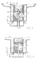
- pan 3 can be truncated-cone shape, with smaller diameter at the bottom and microfilter blades designed accordingly.
- the filtering wall of microfilter as well can be truncated cone in shape.
- microfilter support pin 18 can be replaced by a pin passing through the full axial length of microfilter, or a part thereof, supporting microfilter by means of a shoulder placed either at the base, at the top or at both positions.
- Filter-basin 24 can extend with its peripheral wall 29 and its bottom 28 inside microfilter 12.
- pin 18 supporting the microfilter 12 is hollow, and complete with spraying nozzles 31,32. It acts as inlet duct of the washing water that, in this case, sprays microfilter in the same direction of the recirculation water flow.
- filter-basin 24 is replaced by a cylindrical or truncated-cone extension 33 of filtering plate 11, partly protruding into microfilter 12, down to a large-meshed filtering plate 34, integral with microfilter.
- Plate 34 replaces the spoked support.
- a blade 35 is arranged above plate 34, integral and rotating with microfilter. With its rotation, the latter crushes the soil particles that are collected in the cylindrical extension. This enables particles to pass through plate 34 and to gather within pan 15 (or to be catched by the microfilter).
- microfilter acts as collection filter-basin.
- blade 35 can be integral with extension 33: in this case, the relative motion between solid particles and crushing blade is provoked by the rotation of the plate and the vortex induced by the latter.
Priority Applications (2)
| Application Number | Priority Date | Filing Date | Title |
|---|---|---|---|
| EP20020425497 EP1386575B1 (de) | 2002-07-31 | 2002-07-31 | Geschirrspülmaschine mit durch den Spülwasserstrom rotierbarer Filter- und Zerkleinerungsvorrichtung |
| DE2002606490 DE60206490T2 (de) | 2002-07-31 | 2002-07-31 | Geschirrspülmaschine mit durch den Spülwasserstrom rotierbarer Filter- und Zerkleinerungsvorrichtung |
Applications Claiming Priority (1)
| Application Number | Priority Date | Filing Date | Title |
|---|---|---|---|
| EP20020425497 EP1386575B1 (de) | 2002-07-31 | 2002-07-31 | Geschirrspülmaschine mit durch den Spülwasserstrom rotierbarer Filter- und Zerkleinerungsvorrichtung |
Publications (2)
| Publication Number | Publication Date |
|---|---|
| EP1386575A1 true EP1386575A1 (de) | 2004-02-04 |
| EP1386575B1 EP1386575B1 (de) | 2005-10-05 |
Family
ID=30011316
Family Applications (1)
| Application Number | Title | Priority Date | Filing Date |
|---|---|---|---|
| EP20020425497 Expired - Fee Related EP1386575B1 (de) | 2002-07-31 | 2002-07-31 | Geschirrspülmaschine mit durch den Spülwasserstrom rotierbarer Filter- und Zerkleinerungsvorrichtung |
Country Status (2)
| Country | Link |
|---|---|
| EP (1) | EP1386575B1 (de) |
| DE (1) | DE60206490T2 (de) |
Cited By (52)
| Publication number | Priority date | Publication date | Assignee | Title |
|---|---|---|---|---|
| EP1598465A1 (de) * | 2004-05-17 | 2005-11-23 | The Procter & Gamble Company | Verfahren und Vorrichtung zum Waschen |
| EP1598470A1 (de) * | 2004-05-17 | 2005-11-23 | The Procter & Gamble Company | Verfahren und Vorrichtung zum Waschen |
| WO2006063894A1 (de) | 2004-12-17 | 2006-06-22 | BSH Bosch und Siemens Hausgeräte GmbH | Geschirrspülmaschine mit wartungsarmem siebsystem |
| US20080248075A1 (en) * | 2005-05-04 | 2008-10-09 | Electrolux Home Products Corporation N.V. | Domestic Appliance |
| WO2009077279A2 (de) * | 2007-12-14 | 2009-06-25 | BSH Bosch und Siemens Hausgeräte GmbH | Wasserführendes haushaltsgerät |
| EP2213217A1 (de) * | 2009-01-29 | 2010-08-04 | Electrolux Home Products Corporation N.V. | Geschirrspüler und Verfahren zum Reinigen eines Filters, der zwischen einem Zuber und einem Sammelbehälter eines Geschirrspülers vorgesehen ist |
| EP2263512A1 (de) * | 2009-06-17 | 2010-12-22 | Bonferraro S.p.A. | Haubenartiger industrieller Geschirrspüler mit verbesserter Filteranordnung |
| US20110061682A1 (en) * | 2009-09-17 | 2011-03-17 | Whirlpool Corporation | Rotary drum filter for a dishwashing machine |
| WO2011039253A1 (en) * | 2009-10-01 | 2011-04-07 | Arcelik Anonim Sirketi | A dishwasher comprising a microfilter |
| US20110146714A1 (en) * | 2009-12-21 | 2011-06-23 | Whirlpool Corporation | Rotating filter for a dishwashing machine |
| US20120138106A1 (en) * | 2010-12-03 | 2012-06-07 | Whirlpool Corporation | Dishwasher with single valve to fill multiple compartments |
| US8215322B2 (en) * | 2008-12-22 | 2012-07-10 | Whirlpool Corporation | Dishwasher with soil removal |
| US8240321B2 (en) | 2009-12-18 | 2012-08-14 | Whirlpool Corporation | Magnetic drive controlled rotation for dishwasher spray arm |
| US20120291822A1 (en) * | 2011-05-16 | 2012-11-22 | Whirlpool Corporation | Dishwasher with filter assembly |
| EP2556784A1 (de) * | 2010-12-13 | 2013-02-13 | Whirlpool Corporation | Drehender Filter für einen Geschirrspüler |
| US8733376B2 (en) | 2011-05-16 | 2014-05-27 | Whirlpool Corporation | Dishwasher with filter assembly |
| US8746261B2 (en) | 2009-12-21 | 2014-06-10 | Whirlpool Corporation | Rotating drum filter for a dishwashing machine |
| US8789544B2 (en) * | 2007-08-10 | 2014-07-29 | Lg Electronics Inc. | Filter assembly and dishwasher having the same |
| US9005369B2 (en) | 2011-06-20 | 2015-04-14 | Whirlpool Corporation | Filter assembly for a dishwasher |
| US9010344B2 (en) | 2011-06-20 | 2015-04-21 | Whirlpool Corporation | Rotating filter for a dishwashing machine |
| US9034112B2 (en) | 2010-12-03 | 2015-05-19 | Whirlpool Corporation | Dishwasher with shared heater |
| CN104768441A (zh) * | 2012-11-08 | 2015-07-08 | 伊莱克斯家用产品公司 | 检测过滤器堵塞 |
| US9113766B2 (en) | 2010-11-16 | 2015-08-25 | Whirlpool Corporation | Method and apparatus for dishwasher with common heating element for multiple treating chambers |
| US20150265129A1 (en) * | 2009-12-21 | 2015-09-24 | Whirlpool Corporation | Automatic dishwasher with pump assembly |
| CN104947387A (zh) * | 2014-03-27 | 2015-09-30 | 海尔集团公司 | 一种具有自清洁功能的洗衣机循环节水过滤装置及洗衣机 |
| US20150342438A1 (en) * | 2010-12-03 | 2015-12-03 | Whirlpool Corporation | Dishwasher with unitary wash module |
| US9237836B2 (en) | 2012-05-30 | 2016-01-19 | Whirlpool Corporation | Rotating filter for a dishwasher |
| US9265401B2 (en) | 2011-06-20 | 2016-02-23 | Whirlpool Corporation | Rotating filter for a dishwashing machine |
| US9301667B2 (en) | 2012-02-27 | 2016-04-05 | Whirlpool Corporation | Soil chopping system for a dishwasher |
| US9451862B2 (en) | 2012-06-01 | 2016-09-27 | Whirlpool Corporation | Dishwasher with unitary wash module |
| US9532700B2 (en) | 2012-06-01 | 2017-01-03 | Whirlpool Corporation | Dishwasher with overflow conduit |
| US9554688B2 (en) | 2012-10-23 | 2017-01-31 | Whirlpool Corporation | Rotating filter for a dishwasher and methods of cleaning a rotating filter |
| CN106419795A (zh) * | 2016-12-06 | 2017-02-22 | 江苏理工学院 | 餐具清洁及残羹处理设备 |
| US9668636B2 (en) | 2010-11-16 | 2017-06-06 | Whirlpool Corporation | Method and apparatus for dishwasher with common heating element for multiple treating chambers |
| US9730570B2 (en) | 2012-05-30 | 2017-08-15 | Whirlpool Corporation | Reduced sound with a rotating filter for a dishwasher |
| EP2478818A3 (de) * | 2011-01-21 | 2017-10-25 | BSH Hausgeräte GmbH | Geschirrspülmaschine mit Siebreinigungseinrichtung |
| US9833120B2 (en) | 2012-06-01 | 2017-12-05 | Whirlpool Corporation | Heating air for drying dishes in a dishwasher using an in-line wash liquid heater |
| US9861251B2 (en) | 2011-06-20 | 2018-01-09 | Whirlpool Corporation | Filter with artificial boundary for a dishwashing machine |
| US9918609B2 (en) | 2009-12-21 | 2018-03-20 | Whirlpool Corporation | Rotating drum filter for a dishwashing machine |
| JP2018102557A (ja) * | 2016-12-26 | 2018-07-05 | ホシザキ株式会社 | 洗浄機 |
| EP2671497A3 (de) * | 2012-06-04 | 2018-07-25 | Samsung Electronics Co., Ltd | Geschirrspüler |
| CN108451464A (zh) * | 2017-08-04 | 2018-08-28 | 施贵平 | 清洗机 |
| US10398283B2 (en) | 2013-03-01 | 2019-09-03 | Whirlpool Corporation | Dishwasher with sprayer |
| US10653291B2 (en) | 2011-06-20 | 2020-05-19 | Whirlpool Corporation | Ultra micron filter for a dishwasher |
| WO2020247538A1 (en) | 2019-06-03 | 2020-12-10 | Ecolab Usa Inc. | Dishwasher sump and dishwasher apparatus |
| IT201900018521A1 (it) * | 2019-10-10 | 2021-04-10 | Univ Degli Studi Padova | Pompa, sistema di filtraggio microplastiche e macchina di lavaggio comprendente un tale sistema |
| CN113235719A (zh) * | 2021-06-15 | 2021-08-10 | 广东皓升建设工程有限公司 | 一种市政排水系统 |
| WO2021191215A1 (en) * | 2020-03-23 | 2021-09-30 | Fresh Works Ltd | Filter for a treatment apparatus |
| US11478121B1 (en) | 2021-06-29 | 2022-10-25 | Midea Group Co., Ltd. | Filtration assembly with grinding mechanism |
| WO2023129323A1 (en) * | 2021-12-30 | 2023-07-06 | Repligen Corporation | Vessel, system, and associated method for product concentration |
| EP4154792A4 (de) * | 2020-09-16 | 2023-07-26 | Guangdong Midea White Home Appliance Technology Innovation Center Co., Ltd. | Geschirrwaschvorrichtung und filtervorrichtung dafür |
| CN117547858A (zh) * | 2023-11-27 | 2024-02-13 | 品源(随州)现代农业发展有限公司 | 一种香菇多糖的提取设备及工艺 |
Families Citing this family (8)
| Publication number | Priority date | Publication date | Assignee | Title |
|---|---|---|---|---|
| KR101633932B1 (ko) | 2009-11-25 | 2016-06-27 | 엘지전자 주식회사 | 식기 세척기 |
| US9693672B2 (en) | 2011-09-22 | 2017-07-04 | Whirlpool Corporation | Dishwasher with sprayer |
| US9307885B2 (en) | 2012-01-11 | 2016-04-12 | Whirlpool Corporation | Rotating filter assembly for a dishwasher |
| US9713413B2 (en) | 2013-07-01 | 2017-07-25 | Whirlpool Corporation | Dishwasher for treating dishes |
| US9532699B2 (en) | 2013-07-15 | 2017-01-03 | Whirlpool Corporation | Dishwasher with sprayer |
| DE102017124169A1 (de) * | 2017-10-17 | 2019-04-18 | Miele & Cie. Kg | Sammeltopf für eine Geschirrspülmaschine |
| KR102603450B1 (ko) * | 2018-11-28 | 2023-11-20 | 엘지전자 주식회사 | 히트펌프를 구비한 식기세척기 |
| KR20200064267A (ko) * | 2018-11-28 | 2020-06-08 | 엘지전자 주식회사 | 히트펌프를 구비한 식기세척기 |
Citations (3)
| Publication number | Priority date | Publication date | Assignee | Title |
|---|---|---|---|---|
| CH169630A (de) * | 1933-04-18 | 1934-06-15 | Baumgaertel Otto | Vorrichtung im Spülwasser-Kreislaufsystem von Geschirrwaschmaschinen zum Reinigen des umlaufenden Spülwassers. |
| US5271571A (en) * | 1991-02-19 | 1993-12-21 | Maynard Jr Stuart T | Water driven device for agitating and fragmenting debris in a sink drain |
| EP0752231A1 (de) * | 1995-07-06 | 1997-01-08 | Merloni Elettrodomestici S.p.A. | Geschirrspülmaschine mit Filtereinrichtung und -verfahren |
-
2002
- 2002-07-31 EP EP20020425497 patent/EP1386575B1/de not_active Expired - Fee Related
- 2002-07-31 DE DE2002606490 patent/DE60206490T2/de not_active Expired - Lifetime
Patent Citations (3)
| Publication number | Priority date | Publication date | Assignee | Title |
|---|---|---|---|---|
| CH169630A (de) * | 1933-04-18 | 1934-06-15 | Baumgaertel Otto | Vorrichtung im Spülwasser-Kreislaufsystem von Geschirrwaschmaschinen zum Reinigen des umlaufenden Spülwassers. |
| US5271571A (en) * | 1991-02-19 | 1993-12-21 | Maynard Jr Stuart T | Water driven device for agitating and fragmenting debris in a sink drain |
| EP0752231A1 (de) * | 1995-07-06 | 1997-01-08 | Merloni Elettrodomestici S.p.A. | Geschirrspülmaschine mit Filtereinrichtung und -verfahren |
Cited By (96)
| Publication number | Priority date | Publication date | Assignee | Title |
|---|---|---|---|---|
| EP1598465A1 (de) * | 2004-05-17 | 2005-11-23 | The Procter & Gamble Company | Verfahren und Vorrichtung zum Waschen |
| EP1598470A1 (de) * | 2004-05-17 | 2005-11-23 | The Procter & Gamble Company | Verfahren und Vorrichtung zum Waschen |
| WO2006063894A1 (de) | 2004-12-17 | 2006-06-22 | BSH Bosch und Siemens Hausgeräte GmbH | Geschirrspülmaschine mit wartungsarmem siebsystem |
| US8808462B2 (en) | 2004-12-17 | 2014-08-19 | Bsh Bosch Und Siemens Hausgeraete Gmbh | Dishwasher with a low-maintenance filter system |
| US20080248075A1 (en) * | 2005-05-04 | 2008-10-09 | Electrolux Home Products Corporation N.V. | Domestic Appliance |
| US8763618B2 (en) * | 2005-05-04 | 2014-07-01 | Electrolux Home Products Corporation N.V. | Domestic appliance |
| US8789544B2 (en) * | 2007-08-10 | 2014-07-29 | Lg Electronics Inc. | Filter assembly and dishwasher having the same |
| WO2009077279A2 (de) * | 2007-12-14 | 2009-06-25 | BSH Bosch und Siemens Hausgeräte GmbH | Wasserführendes haushaltsgerät |
| WO2009077279A3 (de) * | 2007-12-14 | 2009-08-13 | Bsh Bosch Siemens Hausgeraete | Wasserführendes haushaltsgerät |
| US8215322B2 (en) * | 2008-12-22 | 2012-07-10 | Whirlpool Corporation | Dishwasher with soil removal |
| EP2213217A1 (de) * | 2009-01-29 | 2010-08-04 | Electrolux Home Products Corporation N.V. | Geschirrspüler und Verfahren zum Reinigen eines Filters, der zwischen einem Zuber und einem Sammelbehälter eines Geschirrspülers vorgesehen ist |
| EP2263512B1 (de) | 2009-06-17 | 2015-06-17 | Bonferraro S.p.A. | Haubenartiger industrieller Geschirrspüler mit verbesserter Filteranordnung |
| EP2263512A1 (de) * | 2009-06-17 | 2010-12-22 | Bonferraro S.p.A. | Haubenartiger industrieller Geschirrspüler mit verbesserter Filteranordnung |
| EP2263512B2 (de) † | 2009-06-17 | 2019-01-09 | Bonferraro S.p.A. | Haubenartiger industrieller Geschirrspüler mit verbesserter Filteranordnung |
| US20110061682A1 (en) * | 2009-09-17 | 2011-03-17 | Whirlpool Corporation | Rotary drum filter for a dishwashing machine |
| US8776808B2 (en) * | 2009-09-17 | 2014-07-15 | Whirlpool Corporation | Rotary drum filter for a dishwashing machine |
| US9538899B2 (en) * | 2009-10-01 | 2017-01-10 | Arcelik Anonim Sirketi | Dishwasher comprising a microfilter |
| US20120180824A1 (en) * | 2009-10-01 | 2012-07-19 | Ismail Kokbiyik | Dishwasher comprising a microfilter |
| WO2011039253A1 (en) * | 2009-10-01 | 2011-04-07 | Arcelik Anonim Sirketi | A dishwasher comprising a microfilter |
| US8240321B2 (en) | 2009-12-18 | 2012-08-14 | Whirlpool Corporation | Magnetic drive controlled rotation for dishwasher spray arm |
| US8746261B2 (en) | 2009-12-21 | 2014-06-10 | Whirlpool Corporation | Rotating drum filter for a dishwashing machine |
| US10779703B2 (en) | 2009-12-21 | 2020-09-22 | Whirlpool Corporation | Rotating drum filter for a dishwashing machine |
| US8667974B2 (en) * | 2009-12-21 | 2014-03-11 | Whirlpool Corporation | Rotating filter for a dishwashing machine |
| US20110146714A1 (en) * | 2009-12-21 | 2011-06-23 | Whirlpool Corporation | Rotating filter for a dishwashing machine |
| US9211047B2 (en) | 2009-12-21 | 2015-12-15 | Whirlpool Corporation | Rotating filter for a dishwashing machine |
| US20150265129A1 (en) * | 2009-12-21 | 2015-09-24 | Whirlpool Corporation | Automatic dishwasher with pump assembly |
| US9918609B2 (en) | 2009-12-21 | 2018-03-20 | Whirlpool Corporation | Rotating drum filter for a dishwashing machine |
| US9375129B2 (en) | 2009-12-21 | 2016-06-28 | Whirlpool Corporation | Rotating filter for a dishwashing machine |
| US9687135B2 (en) | 2009-12-21 | 2017-06-27 | Whirlpool Corporation | Automatic dishwasher with pump assembly |
| US9668636B2 (en) | 2010-11-16 | 2017-06-06 | Whirlpool Corporation | Method and apparatus for dishwasher with common heating element for multiple treating chambers |
| US9113766B2 (en) | 2010-11-16 | 2015-08-25 | Whirlpool Corporation | Method and apparatus for dishwasher with common heating element for multiple treating chambers |
| US9034112B2 (en) | 2010-12-03 | 2015-05-19 | Whirlpool Corporation | Dishwasher with shared heater |
| US9572473B2 (en) | 2010-12-03 | 2017-02-21 | Whirlpool Corporation | Dishwasher with unitary wash module |
| US20120138106A1 (en) * | 2010-12-03 | 2012-06-07 | Whirlpool Corporation | Dishwasher with single valve to fill multiple compartments |
| US20150342438A1 (en) * | 2010-12-03 | 2015-12-03 | Whirlpool Corporation | Dishwasher with unitary wash module |
| US9532697B2 (en) * | 2010-12-03 | 2017-01-03 | Whirlpool Corporation | Dishwasher with unitary wash module |
| US9532696B2 (en) | 2010-12-03 | 2017-01-03 | Whirlpool Corporation | Dishwasher with unitary wash module |
| EP2556784A1 (de) * | 2010-12-13 | 2013-02-13 | Whirlpool Corporation | Drehender Filter für einen Geschirrspüler |
| US8627832B2 (en) | 2010-12-13 | 2014-01-14 | Whirlpool Corporation | Rotating filter for a dishwashing machine |
| US9364131B2 (en) | 2010-12-13 | 2016-06-14 | Whirlpool Corporation | Rotating filter for a dishwashing machine |
| EP2478818A3 (de) * | 2011-01-21 | 2017-10-25 | BSH Hausgeräte GmbH | Geschirrspülmaschine mit Siebreinigungseinrichtung |
| US10004377B2 (en) | 2011-01-21 | 2018-06-26 | BSH Hausgeräte GmbH | Dishwasher |
| US9538898B2 (en) | 2011-05-16 | 2017-01-10 | Whirlpool Corporation | Dishwasher with filter assembly |
| US9107559B2 (en) * | 2011-05-16 | 2015-08-18 | Whirlpool Corporation | Dishwasher with filter assembly |
| US20140230852A1 (en) * | 2011-05-16 | 2014-08-21 | Whirlpool Corporation | Dishwasher with filter assembly |
| US9700196B2 (en) | 2011-05-16 | 2017-07-11 | Whirlpool Corporation | Dishwasher with filter assembly |
| US11882977B2 (en) | 2011-05-16 | 2024-01-30 | Whirlpool Corporation | Dishwasher with filter assembly |
| US8733376B2 (en) | 2011-05-16 | 2014-05-27 | Whirlpool Corporation | Dishwasher with filter assembly |
| US9167950B2 (en) * | 2011-05-16 | 2015-10-27 | Whirlpool Corporation | Dishwasher with filter assembly |
| US20120291822A1 (en) * | 2011-05-16 | 2012-11-22 | Whirlpool Corporation | Dishwasher with filter assembly |
| US10813525B2 (en) | 2011-06-20 | 2020-10-27 | Whirlpool Corporation | Ultra micron filter for a dishwasher |
| US10314457B2 (en) | 2011-06-20 | 2019-06-11 | Whirlpool Corporation | Filter with artificial boundary for a dishwashing machine |
| US10178939B2 (en) | 2011-06-20 | 2019-01-15 | Whirlpool Corporation | Filter with artificial boundary for a dishwashing machine |
| US10653291B2 (en) | 2011-06-20 | 2020-05-19 | Whirlpool Corporation | Ultra micron filter for a dishwasher |
| US9861251B2 (en) | 2011-06-20 | 2018-01-09 | Whirlpool Corporation | Filter with artificial boundary for a dishwashing machine |
| US9265401B2 (en) | 2011-06-20 | 2016-02-23 | Whirlpool Corporation | Rotating filter for a dishwashing machine |
| US10070769B2 (en) | 2011-06-20 | 2018-09-11 | Whirlpool Corporation | Rotating filter for a dishwashing machine |
| US10058227B2 (en) | 2011-06-20 | 2018-08-28 | Whirlpool Corporation | Filter assembly for a dishwasher |
| US9010344B2 (en) | 2011-06-20 | 2015-04-21 | Whirlpool Corporation | Rotating filter for a dishwashing machine |
| US9005369B2 (en) | 2011-06-20 | 2015-04-14 | Whirlpool Corporation | Filter assembly for a dishwasher |
| US9301667B2 (en) | 2012-02-27 | 2016-04-05 | Whirlpool Corporation | Soil chopping system for a dishwasher |
| US9730570B2 (en) | 2012-05-30 | 2017-08-15 | Whirlpool Corporation | Reduced sound with a rotating filter for a dishwasher |
| US11134825B2 (en) | 2012-05-30 | 2021-10-05 | Whirlpool Corporation | Reduced sound with a rotating filter for a dishwasher |
| US9237836B2 (en) | 2012-05-30 | 2016-01-19 | Whirlpool Corporation | Rotating filter for a dishwasher |
| US10376128B2 (en) | 2012-05-30 | 2019-08-13 | Whirlpool Corporation | Reduced sound with a rotating filter for a dishwasher |
| US10076226B2 (en) | 2012-05-30 | 2018-09-18 | Whirlpool Corporation | Rotating filter for a dishwasher |
| US9451862B2 (en) | 2012-06-01 | 2016-09-27 | Whirlpool Corporation | Dishwasher with unitary wash module |
| US9532700B2 (en) | 2012-06-01 | 2017-01-03 | Whirlpool Corporation | Dishwasher with overflow conduit |
| US9833120B2 (en) | 2012-06-01 | 2017-12-05 | Whirlpool Corporation | Heating air for drying dishes in a dishwasher using an in-line wash liquid heater |
| EP2671497A3 (de) * | 2012-06-04 | 2018-07-25 | Samsung Electronics Co., Ltd | Geschirrspüler |
| US9554688B2 (en) | 2012-10-23 | 2017-01-31 | Whirlpool Corporation | Rotating filter for a dishwasher and methods of cleaning a rotating filter |
| US9826882B2 (en) | 2012-10-23 | 2017-11-28 | Whirlpool Corporation | Rotating filter for a dishwasher and methods of cleaning a rotating filter |
| US9649007B2 (en) | 2012-10-23 | 2017-05-16 | Whirlpool Corporation | Rotating filter for a dishwasher and methods of cleaning a rotating filter |
| US9757008B2 (en) | 2012-10-23 | 2017-09-12 | Whirlpool Corporation | Rotating filter for a dishwasher and methods of cleaning a rotating filter |
| US9962060B2 (en) | 2012-10-23 | 2018-05-08 | Whirlpool Corporation | Rotating filter for a dishwasher and methods of cleaning a rotating filter |
| CN104768441A (zh) * | 2012-11-08 | 2015-07-08 | 伊莱克斯家用产品公司 | 检测过滤器堵塞 |
| CN104768441B (zh) * | 2012-11-08 | 2018-07-03 | 伊莱克斯家用产品公司 | 检测过滤器堵塞 |
| US10398283B2 (en) | 2013-03-01 | 2019-09-03 | Whirlpool Corporation | Dishwasher with sprayer |
| CN104947387A (zh) * | 2014-03-27 | 2015-09-30 | 海尔集团公司 | 一种具有自清洁功能的洗衣机循环节水过滤装置及洗衣机 |
| CN106419795A (zh) * | 2016-12-06 | 2017-02-22 | 江苏理工学院 | 餐具清洁及残羹处理设备 |
| JP2018102557A (ja) * | 2016-12-26 | 2018-07-05 | ホシザキ株式会社 | 洗浄機 |
| CN108451464B (zh) * | 2017-08-04 | 2023-10-31 | 施贵平 | 清洗机 |
| CN108451464A (zh) * | 2017-08-04 | 2018-08-28 | 施贵平 | 清洗机 |
| EP3975814A4 (de) * | 2019-06-03 | 2023-10-25 | Ecolab USA Inc. | Sammelbehälter für geschirrspülmaschine und geschirrspülmaschine |
| JP2022535825A (ja) * | 2019-06-03 | 2022-08-10 | エコラボ ユーエスエー インコーポレイティド | 食器洗い機サンプおよび食器洗い機装置 |
| WO2020247538A1 (en) | 2019-06-03 | 2020-12-10 | Ecolab Usa Inc. | Dishwasher sump and dishwasher apparatus |
| US11903545B2 (en) | 2019-06-03 | 2024-02-20 | Ecolab Usa Inc. | Dishwasher sump and dishwasher apparatus |
| IT201900018521A1 (it) * | 2019-10-10 | 2021-04-10 | Univ Degli Studi Padova | Pompa, sistema di filtraggio microplastiche e macchina di lavaggio comprendente un tale sistema |
| WO2021191215A1 (en) * | 2020-03-23 | 2021-09-30 | Fresh Works Ltd | Filter for a treatment apparatus |
| EP4154792A4 (de) * | 2020-09-16 | 2023-07-26 | Guangdong Midea White Home Appliance Technology Innovation Center Co., Ltd. | Geschirrwaschvorrichtung und filtervorrichtung dafür |
| CN113235719A (zh) * | 2021-06-15 | 2021-08-10 | 广东皓升建设工程有限公司 | 一种市政排水系统 |
| US11478121B1 (en) | 2021-06-29 | 2022-10-25 | Midea Group Co., Ltd. | Filtration assembly with grinding mechanism |
| US11903544B2 (en) | 2021-06-29 | 2024-02-20 | Midea Group Co., Ltd. | Filtration assembly with grinding mechanism |
| WO2023129323A1 (en) * | 2021-12-30 | 2023-07-06 | Repligen Corporation | Vessel, system, and associated method for product concentration |
| CN117547858A (zh) * | 2023-11-27 | 2024-02-13 | 品源(随州)现代农业发展有限公司 | 一种香菇多糖的提取设备及工艺 |
| CN117547858B (zh) * | 2023-11-27 | 2024-04-19 | 品源(随州)现代农业发展有限公司 | 一种香菇多糖的提取设备及工艺 |
Also Published As
| Publication number | Publication date |
|---|---|
| DE60206490T2 (de) | 2006-05-18 |
| EP1386575B1 (de) | 2005-10-05 |
| DE60206490D1 (de) | 2005-11-10 |
Similar Documents
| Publication | Publication Date | Title |
|---|---|---|
| EP1386575B1 (de) | Geschirrspülmaschine mit durch den Spülwasserstrom rotierbarer Filter- und Zerkleinerungsvorrichtung | |
| CA1071507A (en) | Dishwasher filter flushing system | |
| US5762080A (en) | Dishwasher cycle pulsing pump out of collection chamber | |
| US4150680A (en) | Dishwasher soil separator | |
| US5909743A (en) | Automatic purge filtration system for a dishwasher | |
| US5143306A (en) | Waste disintegrating device for a dishwasher | |
| US5333631A (en) | Cleaning wash-arm for dishwashing filter | |
| CA2183285C (en) | Soil separation channel for dishwasher pump system | |
| US4972861A (en) | Washing machine including improved apparatus for cleaning a recirculating filter thereof | |
| US5628334A (en) | Dishwasher with food particle macerator and mincer | |
| US6782899B2 (en) | Dishwasher | |
| US4347861A (en) | Dishwasher soil separator | |
| US4350306A (en) | Chopper for dishwasher soil separator | |
| CN101884520B (zh) | 洗碗机 | |
| US20130174879A1 (en) | Rotating filter assembly for a dishwasher | |
| CN111759253A (zh) | 一种洗碗机碎渣与水循环集成系统及其运作方法 | |
| CN218683919U (zh) | 一种优化排液阀的食品加工机 | |
| EP0842632B1 (de) | Filtereinrichtung mit automatischer Reinigungsvorrichtung für Geschirrspülmaschine | |
| CN109717804B (zh) | 一种用于清洗机的集渣结构以及应用有该集渣结构的清洗机 | |
| CN111227749A (zh) | 用于清洗机的旋转喷臂及应用有该旋转喷臂的清洗机 | |
| EP0913119B1 (de) | Nebenabflusssystem | |
| KR100457597B1 (ko) | 식기세척기의 필터장치 | |
| KR100457596B1 (ko) | 식기세척기의 필터장치 | |
| CN214760961U (zh) | 一种渣篮、具有该渣篮的水槽式清洗机 | |
| CN213129384U (zh) | 一种洗碗机碎渣与水循环集成系统 |
Legal Events
| Date | Code | Title | Description |
|---|---|---|---|
| PUAI | Public reference made under article 153(3) epc to a published international application that has entered the european phase |
Free format text: ORIGINAL CODE: 0009012 |
|
| AK | Designated contracting states |
Kind code of ref document: A1 Designated state(s): AT BE BG CH CY CZ DE DK EE ES FI FR GB GR IE IT LI LU MC NL PT SE SK TR |
|
| AX | Request for extension of the european patent |
Extension state: AL LT LV MK RO SI |
|
| 17P | Request for examination filed |
Effective date: 20040213 |
|
| 17Q | First examination report despatched |
Effective date: 20040910 |
|
| AKX | Designation fees paid |
Designated state(s): DE FR GB IT |
|
| GRAP | Despatch of communication of intention to grant a patent |
Free format text: ORIGINAL CODE: EPIDOSNIGR1 |
|
| GRAS | Grant fee paid |
Free format text: ORIGINAL CODE: EPIDOSNIGR3 |
|
| GRAA | (expected) grant |
Free format text: ORIGINAL CODE: 0009210 |
|
| AK | Designated contracting states |
Kind code of ref document: B1 Designated state(s): DE FR GB IT |
|
| REG | Reference to a national code |
Ref country code: GB Ref legal event code: FG4D |
|
| REF | Corresponds to: |
Ref document number: 60206490 Country of ref document: DE Date of ref document: 20051110 Kind code of ref document: P |
|
| ET | Fr: translation filed | ||
| PLBE | No opposition filed within time limit |
Free format text: ORIGINAL CODE: 0009261 |
|
| STAA | Information on the status of an ep patent application or granted ep patent |
Free format text: STATUS: NO OPPOSITION FILED WITHIN TIME LIMIT |
|
| 26N | No opposition filed |
Effective date: 20060706 |
|
| REG | Reference to a national code |
Ref country code: FR Ref legal event code: PLFP Year of fee payment: 15 |
|
| REG | Reference to a national code |
Ref country code: FR Ref legal event code: PLFP Year of fee payment: 16 |
|
| PGFP | Annual fee paid to national office [announced via postgrant information from national office to epo] |
Ref country code: FR Payment date: 20170731 Year of fee payment: 16 Ref country code: IT Payment date: 20170706 Year of fee payment: 16 Ref country code: GB Payment date: 20170719 Year of fee payment: 16 |
|
| PGFP | Annual fee paid to national office [announced via postgrant information from national office to epo] |
Ref country code: DE Payment date: 20170929 Year of fee payment: 16 |
|
| REG | Reference to a national code |
Ref country code: DE Ref legal event code: R119 Ref document number: 60206490 Country of ref document: DE |
|
| GBPC | Gb: european patent ceased through non-payment of renewal fee |
Effective date: 20180731 |
|
| PG25 | Lapsed in a contracting state [announced via postgrant information from national office to epo] |
Ref country code: DE Free format text: LAPSE BECAUSE OF NON-PAYMENT OF DUE FEES Effective date: 20190201 Ref country code: GB Free format text: LAPSE BECAUSE OF NON-PAYMENT OF DUE FEES Effective date: 20180731 Ref country code: FR Free format text: LAPSE BECAUSE OF NON-PAYMENT OF DUE FEES Effective date: 20180731 |
|
| PG25 | Lapsed in a contracting state [announced via postgrant information from national office to epo] |
Ref country code: IT Free format text: LAPSE BECAUSE OF NON-PAYMENT OF DUE FEES Effective date: 20180731 |