EP1386411B1 - Verfahren zur detektion von mehrwegesignalen - Google Patents
Verfahren zur detektion von mehrwegesignalen Download PDFInfo
- Publication number
- EP1386411B1 EP1386411B1 EP01943035A EP01943035A EP1386411B1 EP 1386411 B1 EP1386411 B1 EP 1386411B1 EP 01943035 A EP01943035 A EP 01943035A EP 01943035 A EP01943035 A EP 01943035A EP 1386411 B1 EP1386411 B1 EP 1386411B1
- Authority
- EP
- European Patent Office
- Prior art keywords
- impulse response
- reference signal
- cross
- signal
- scaled
- Prior art date
- Legal status (The legal status is an assumption and is not a legal conclusion. Google has not performed a legal analysis and makes no representation as to the accuracy of the status listed.)
- Expired - Lifetime
Links
- 238000000034 method Methods 0.000 title claims abstract description 45
- 230000004044 response Effects 0.000 claims abstract description 87
- 238000001514 detection method Methods 0.000 claims description 7
- 238000010586 diagram Methods 0.000 description 18
- 230000006870 function Effects 0.000 description 4
- 101100129500 Caenorhabditis elegans max-2 gene Proteins 0.000 description 2
- 101100083446 Danio rerio plekhh1 gene Proteins 0.000 description 2
- 230000003292 diminished effect Effects 0.000 description 2
- 230000002123 temporal effect Effects 0.000 description 2
- 230000005540 biological transmission Effects 0.000 description 1
- 150000001875 compounds Chemical class 0.000 description 1
- 230000003247 decreasing effect Effects 0.000 description 1
- 230000001934 delay Effects 0.000 description 1
- 230000001419 dependent effect Effects 0.000 description 1
- 230000001066 destructive effect Effects 0.000 description 1
- 238000001914 filtration Methods 0.000 description 1
- 238000007781 pre-processing Methods 0.000 description 1
Images



Classifications
-
- H—ELECTRICITY
- H04—ELECTRIC COMMUNICATION TECHNIQUE
- H04B—TRANSMISSION
- H04B1/00—Details of transmission systems, not covered by a single one of groups H04B3/00 - H04B13/00; Details of transmission systems not characterised by the medium used for transmission
- H04B1/69—Spread spectrum techniques
- H04B1/707—Spread spectrum techniques using direct sequence modulation
- H04B1/7097—Interference-related aspects
- H04B1/711—Interference-related aspects the interference being multi-path interference
- H04B1/7115—Constructive combining of multi-path signals, i.e. RAKE receivers
-
- H—ELECTRICITY
- H04—ELECTRIC COMMUNICATION TECHNIQUE
- H04B—TRANSMISSION
- H04B1/00—Details of transmission systems, not covered by a single one of groups H04B3/00 - H04B13/00; Details of transmission systems not characterised by the medium used for transmission
- H04B1/69—Spread spectrum techniques
- H04B1/707—Spread spectrum techniques using direct sequence modulation
- H04B1/7097—Interference-related aspects
- H04B1/711—Interference-related aspects the interference being multi-path interference
- H04B1/7115—Constructive combining of multi-path signals, i.e. RAKE receivers
- H04B1/7117—Selection, re-selection, allocation or re-allocation of paths to fingers, e.g. timing offset control of allocated fingers
Definitions
- the invention relates to a method for detecting multipath signals, in particular for operating a RAKE receiver, according to claim 1 and a RAKE receiver according to the preamble of claim 5.
- signals In a mobile channel, signals generally propagate via multiple paths (multipath propagation). Every single one Receive signal has according to its Ubertragungspfad a different transit time, amplitude and Doppler shift on. The various reception signals are superimposed at the antenna of a receiver either constructive or destructive and thereby complicate the detection of the by the Signals transmitted symbols.
- Such a RAKE receiver allows a significant profit through the use of multipath signals that come with different Propagation delays at a receiving antenna a mobile device arrive. This is done by the antenna incoming signal in the receiver in multiple paths, the so-called "fingers" of the RAKE receiver, processed. Everyone This finger is each with an optimized phase position the pseudo noise episodes, which are used to encode one over the mobile channel to be transmitted signal on each set a component of the received multipath signals.
- a RAKE receiver has a Mobile station at least three and a base station at least four such fingers. Furthermore, there are both in the mobile station as well as in the base station at least one each "Search finger", which is constantly looking for stronger multipath signals examined. Once the search finger a stronger multipath signal discovered, becomes the finger of the hitherto weakest multipath signal optimally adjusted to the new stronger multipath signal. Typically, it can be used in the mobile station up to to three and in the base station up to four of the strongest Multipath signals with a time delay of at least 0.8 to 1 ⁇ s demodulated and using maximum ratio combining be combined.
- the object of the present invention is therefore a method for the detection of multipath signals and a corresponding To propose RAKE receivers, the one opposite known Detection method less complexity of data processing and thus fundamentally shorter response times as well have a lower demand for processor capacity.
- the idea underlying the invention is, from the total impulse response successively peaks or maxima means To determine cross-correlation. After the determination of a first maximum, the total impulse response becomes a reference signal, that for determining the first maximum with the total impulse response was cross-correlated, diminished. This means, that step by step out of the overall impulse response By means of the reference signal maxima are determined, which are the indicate possible position of fingers.
- the method is used in a RAKE receiver.
- RAKE receivers become in particular used in code division mobile radio systems.
- a RAKE receiver in principle uses the propagation time differences of multipath signals by having multiple paths or fingers, each to the phase position of a signal of the multipath signals is set.
- the in the individual paths or fingers of the RAKE receiver are optimized signals then combined into a common received signal.
- the method according to the invention can function as a function of a RAKE receiver are significantly improved, especially in terms a total impulse response in the individual signal components only very short time differences (about 1 ⁇ 4 chip) have.
- the reference signal used according to the method a fingerpattern, which is a typical cellphone channel equivalent.
- a typical mobile channel is this understood a mobile channel, the limited transit time differences due to multipath propagation of transmitted Has signals and a good approximation for a variety represents real mobile radio channels.
- the reference signal is preferably scaled such that a scaled reference signal substantially with that in step b) of the method determined maximum cross-correlation matches. This will increase the efficiency of step c) the process significantly improved.
- the invention relates to a receiver for carrying out of the method, the multiple paths or fingers for Processing of received multipath signals has.
- the receiver assigns a cross-correlator Cross-correlating a total impulse response with a reference signal, a memory for the total impulse response and a scaler and subtractor for reducing the overall impulse response around the reference signal.
- the cross-correlator, the memory and the Scaler and subtractor as program routines of a program for a signal processor for processing the total impulse response or as programmable or hardwired Logic, especially in an ASIC trained.
- a signal processor has special functions and / or commands Signal processing and can therefore the aforementioned program routines run very efficiently.
- such is one Signal processor operable at a very high clock frequency, to be able to process the occurring high data rates.
- the implementation in logic has the advantage that it is very fast and therefore handles even higher data rates can.
- FIG. 1 will be brief in the following brief Sequence of the inventive method to an embodiment clarified. Subsequently, with reference to FIG. 2, 3, 4 and 5 show exemplary courses of total impulse response and Search pattern or reference signal explained.
- the total impulse response 10.of received multipath signals is shown in diagram A.
- the total impulse response 10 essentially has three maxima 12, 14 and 16, which occur at different reception times.
- the total impulse response 10 is cross-correlated with a reference signal (not shown).
- the result of the cross-correlation and determination of a maximum and scaling factor is the signal shown in diagram B, which essentially has a maximum 18 corresponding to maximum 14 at time ⁇ max1 in diagram A, likewise at time ⁇ max1 .
- the total impulse response 10 shown in diagram A is reduced by the scaled reference signal.
- the result of this subtraction is shown in diagram C of FIG.
- the signal 20 shown in diagram C now has essentially two maxima 22 and 24.
- the maximum 22 at the time ⁇ max2 should be determined from the signal 20 in a next step.
- the determination is again carried out by means of the cross-correlation according to the method according to the invention.
- the result of the cross-correlation is shown in Diagram D. This shows a maximum 26 at the time ⁇ max2 , which corresponds to a second signal component in the total impulse response .
- the signal 20 shown in diagram C is in turn reduced by the scaled reference signal, so that the signal 28 shown in diagram E is obtained.
- This has essentially only a maximum 30 at the time ⁇ max3 .
- This maximum corresponds to a third signal component in the total impulse response 10.
- the maximum 32 shown in diagram F is finally obtained at the instant ⁇ max3 .
- this again becomes the diagram E illustrated signal 28 around the scaled reference signal decreased, resulting in the graph shown in diagram G.
- Signal 34 results.
- This signal 34 essentially comprises only noise, so that at this point the inventive Method for detecting multipath signals ends. Specifically, this means that the diagrams shown in diagrams B, D and F illustrated maxima 18, 26 and 32 correspondingly different Propagation paths and maturities in the mobile radio channel have been extracted.
- Fig. 2 is the exemplary course of a total impulse response 11 after passing through a matched filter in one RAKE receiver shown.
- the total impulse response comprises signal components of the different propagation paths in a mobile channel.
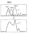
- Fig. 5 is an example of how such a Total impulse response 13 from the superimposition of several individual impulses 15, 17, 19 and a noise component 21 composed.
- the noise component 21 is with noise designated.
- the individual impulses each correspond to a propagation path and typically meet at different times in a receiver at.
- FIG. 3 is an exemplary course of a virtual total impulse response shown.
- This virtual total impulse response consists of a scalable search pattern or reference signal and an additional component ⁇ together.
- the search pattern is with a scaling factor ⁇ scaled.
- the component ⁇ corresponds to a noise component.
- FIG. 4 shows the search pattern contained in the virtual total impulse response of FIG. 3.
- a main maximum of the search pattern is at ⁇ min , a secondary maximum at ⁇ max .
- the flowchart shown in Fig. 6 illustrates, with which steps out of a total impulse response the individual Finger positions are extracted according to the invention.
- the first step S1 becomes the impulse response received by a receiver a mobile channel subjected to a matched filtering.
- a finger position counter is set to zero.
- the total impulse response cross-correlated with a reference function.
- the result of Cross-correlation is processed in a third step S3.
- A1 is checked if the maximum is a finger. Is found that the maximum is not a finger, the process is over, since the "residual" total impulse response only contains noise.
- step S4 the maximum is detected finger position and the total impulse response scaled by the proportionality factor ⁇ Search pattern or reference signal reduced.
- the finger position counter will also be incremented.
- a subsequent one Interrogation step A2 checks if the value of the finger position counter has already exceeded a predetermined value.
- the default value corresponds to a predetermined number of Maxima or finger positions.
- the method can namely a certain number of maxima or finger positions aborted become. Typically, this number corresponds to Maxima or finger positions on the "fingers" of a RAKE receiver. However, if the given value has not yet been reached, the process continues with step S2.
- the search pattern in the Total impulse response is detected.
- the method of the least squares applied Specifically, this means that the search pattern is detected in the total impulse response right there is where the quadratic deviation of the total impulse response from the virtual total impulse response (the only one Propagation path) is minimal. This will be essentially obtained by the cross-correlation. In other words This means that at the point where the cross-correlation the total impulse response with the search pattern or the reference signal is maximum, a finger position is present. Particular importance is attached to the proportionality factor ⁇ too. Namely, the total impulse response is scaled by the one scaled by ⁇ Search pattern or reference signal reduced.
- the receiver R comprises in this sense a cross-correlator 40, a matched filter 42, and a subtractor and scaler 44. Further, a multiplexer 46 is provided, whose Output signal is supplied to a pulse response memory.
- a data signal transmitted over a mobile radio channel is supplied to the matched filter 42 in the receiver R.
- the matched filter 42 is used to equalize the received Data signal.
- the matched filter supplies as output signal 42 the total impulse response 54 of the mobile radio channel.
- the Total impulse response 54 is a first input of a multiplexer 46 supplied. Via the multiplexer 46 is the total impulse response 54 an impulse response memory 48 can be fed. This serves to temporarily store the samples of the total impulse response.
- the output of the impulse response memory 48 is the cross-correlator 40 and the subtractor and Scaler 44 supplied.
- the cross-correlator 40 cross-correlates the total impulse response stored in the impulse response memory 48 with a supplied reference signal 50.
- cross correlator 40 which is a finger position signal 56 is the subtractor and scaler 44 fed. This is also the reference signal via a switch 50 can be fed.
- the subtractor and scaler 44 first scales the reference signal supplied through the switch 50 corresponding to the finger position signal 56. Then diminished he the supplied and in the impulse response memory 48 cached total impulse response around the scaled reference signal 50.
- the subtraction output 52 is called second input signal to the multiplexer 46, respectively.
- the RAKE receiver R works as follows:
- a signal received via an antenna is subjected to the usual signal preprocessing and the Matched filter 42 supplied.
- the output signal of the matched filter 42 is the total impulse response 54 and is transmitted over the Multiplexer cached directly in the impulse response memory 48. More specifically, the impulse response memory stores 48 samples of the total impulse response 54.
- the impulse response memory 48 cached total impulse response is via the correlator 40 and the subtractor and Scaler 44 processed by the method according to the invention.
- the multiplexer 46 is set to switched second input, d. H. the subtraction output 52 is sent via the multiplexer 46 in the impulse response memory 48 cached.
- Control will now be in the impulse response memory 48 cached total impulse response as long as after process according to the invention, until either the Finger position signal 56 no longer new finger positions indicates or already a predetermined number of finger positions was determined. This can be done, for example, by simple Counting signaled by the finger position signal 56 Finger positions take place.
Landscapes
- Engineering & Computer Science (AREA)
- Computer Networks & Wireless Communication (AREA)
- Signal Processing (AREA)
- Noise Elimination (AREA)
Abstract
Description
- 10, 11, 13
- Gesamtimpulsantwort
- 12, 14, 16, 22, 24, 30
- Maximum
- 15, 17, 19
- Einzelimpulse
- 18, 26, 32
- detektiertes Maximum
- 20, 28
- Mehrwegesignale, um das Referenzsignal vermindert
- 21
- Rauschanteil
- 34
- Rauschsignale
- 40
- Kreuzkorrelator
- 42
- Matched-Filter
- 44
- Subtrahierer und Skalierer
- 46
- Multiplexer/Demultiplexer
- 48
- Impulsantwortspeicher
- 50
- Referenzsignal
- 52
- Subtrahierungsausgangssignal
- 54
- Gesamtimpulsantwort
- 56
- Fingerpositions-Signal
- R
- RAKE-Empfänger
Claims (7)
- Verfahren zur Detektion von über einen Mobilfunkkanal empfangenen Mehrwegesignalen (10), insbesondere zum Betrieb eines RAKE-Empfängers, mit den folgenden Schritten:a) Kreuzkorrelieren einer Gesamtimpulsantwort (10) mit einem Referenzsignal,b) Ermitteln und Speichern eines Maximums (18) des Ergebnisses der Kreuzkorrelation und eines Proportionalitätsfaktors α,c) Vermindern der Gesamtimpulsantwort (10) um das mit α skalierte Referenzsignal,d) Durchführen der Schritte a) bis c) mit der um das skalierte Referenzsignal verminderten Gesamtimpulsantwort (10, 20, 28) bis eine vorgegebene Anzahl von Maxima (18, 26, 32) erhalten worden ist oder bis der Skalierungsfaktor α einen vorgegebenen Wert unterschreitet.
- Verfahren nach Anspruch 1,
dadurch gekennzeichnet, dass
das Referenzsignal die fensterbegrenzte Impulsantwort eines Pfades des Mobilfunkkanals ist. - Verfahren nach Anspruch 1 oder 2,
dadurch gekennzeichnet, dass
das Referenzsignal derart skaliert ist, dass das skalierte Referenzsignal im wesentlichen mit dem in Schritt b) ermittelten Maximum der Kreuzkorrelation übereinstimmt. - Verfahren nach einem der vorhergehenden Ansprüche,
dadurch gekennzeichnet, dass
bei Durchführung der Schritte a) bis d) im wesentlichen Multiply-and-Accumulate-Operationen durchgeführt werden. - RAKE-Empfänger zur Durchführung des Verfahrens nach einem der vorhergehenden Ansprüche, der mehrere Pfade bzw. Finger zur Verarbeitung von empfangenen Mehrwegesignalen (10) aufweist,
dadurch gekennzeichnet, dassein Kreuzkorrelator (40) zum Kreuzkorrelieren der Gesamtimpulsantwort (10) mit einem Referenzsignal (50),einen Speicher (48) für die Gesamtimpulsantwort undein Subtrahierer und Skalierer (44) zum Vermindern der Gesamtimpulsantwort um das skalierte Referenzsignal vorgesehen sind. - RAKE-Empfänger nach Anspruch 5,
dadurch gekennzeichnet, dass
ferner eine Steuerungslogik zur Steuerung des Kreuzkorrelators (40) und des Subtrahierers und Skalierers (44) vorgesehen ist. - RAKE-Empfänger nach Anspruch 5 oder 6,
dadurch gekennzeichnet, dass
der Kreuzkorrelator (40), der Speicher (48) und der Subtrahierer und Skalierer (44) als Programmroutinen eines Programms für einen Signalprozessor zur Verarbeitung von Mehrwegesignalen oder als programmierbare oder fest verdrahtete Logik, insbesondere in einem ASIC, ausgebildet sind.
Applications Claiming Priority (1)
| Application Number | Priority Date | Filing Date | Title |
|---|---|---|---|
| PCT/DE2001/001740 WO2002091607A1 (de) | 2001-05-08 | 2001-05-08 | Verfahren zur detektion von mehrwegsignalen |
Publications (2)
| Publication Number | Publication Date |
|---|---|
| EP1386411A1 EP1386411A1 (de) | 2004-02-04 |
| EP1386411B1 true EP1386411B1 (de) | 2005-07-20 |
Family
ID=5648239
Family Applications (1)
| Application Number | Title | Priority Date | Filing Date |
|---|---|---|---|
| EP01943035A Expired - Lifetime EP1386411B1 (de) | 2001-05-08 | 2001-05-08 | Verfahren zur detektion von mehrwegesignalen |
Country Status (4)
| Country | Link |
|---|---|
| US (1) | US7292621B2 (de) |
| EP (1) | EP1386411B1 (de) |
| DE (1) | DE50106830D1 (de) |
| WO (1) | WO2002091607A1 (de) |
Families Citing this family (5)
| Publication number | Priority date | Publication date | Assignee | Title |
|---|---|---|---|---|
| US20060088081A1 (en) * | 2004-10-22 | 2006-04-27 | Time Domain Corporation | Transmit-rake apparatus in communication systems and associated methods |
| EP2273687B1 (de) * | 2009-07-01 | 2016-12-07 | Telefonaktiebolaget LM Ericsson (publ) | Mehrweg-Taktverfolgung und -beeinträchtigungsmodellierung zur Verbesserung der G-Rake-Empfängerleistung in Mobilitätsszenarien |
| US9633164B2 (en) | 2014-10-10 | 2017-04-25 | Signal Integrity Software, Inc. | System and method for signal integrity waveform decomposition analysis |
| TWI635732B (zh) * | 2016-10-05 | 2018-09-11 | 晨星半導體股份有限公司 | 多載波系統的回音偵測電路及方法 |
| CN107979550B (zh) * | 2016-10-25 | 2021-03-23 | 联发科技股份有限公司 | 多载波系统的回音检测电路及方法 |
Family Cites Families (8)
| Publication number | Priority date | Publication date | Assignee | Title |
|---|---|---|---|---|
| US5648983A (en) * | 1995-04-24 | 1997-07-15 | Lucent Technologies Inc. | CDMA rake receiver with sub-chip resolution |
| FR2737362B1 (fr) * | 1995-07-25 | 1997-10-10 | Matra Communication | Procede de selection des retards de propagation retenus pour recevoir des messages transmis par radiocommunication a etalement de spectre |
| GB2317465B (en) * | 1996-09-23 | 2000-11-15 | Advanced Risc Mach Ltd | Data processing apparatus registers. |
| JP2850958B2 (ja) * | 1997-05-02 | 1999-01-27 | 日本電気株式会社 | スペクトラム拡散通信用受信装置 |
| DE19824218C1 (de) | 1998-05-29 | 2000-03-23 | Ericsson Telefon Ab L M | Multipfad-Ausbreitungsverzögerungs-Bestimmungsvorrichtung unter Verwendung von periodisch eingefügten Pilotsymbolen |
| JP2000307470A (ja) * | 1999-04-16 | 2000-11-02 | Matsushita Electric Ind Co Ltd | 受信装置 |
| US6324210B1 (en) * | 1999-12-17 | 2001-11-27 | Golden Bridge Technology Incorporated | Sliding matched filter with flexible hardware complexity |
| JP3468189B2 (ja) * | 2000-02-02 | 2003-11-17 | 日本電気株式会社 | パターン生成回路及びそれを用いたマルチパス検出回路並びにそのマルチパス検出方法 |
-
2001
- 2001-05-08 EP EP01943035A patent/EP1386411B1/de not_active Expired - Lifetime
- 2001-05-08 DE DE50106830T patent/DE50106830D1/de not_active Expired - Lifetime
- 2001-05-08 WO PCT/DE2001/001740 patent/WO2002091607A1/de not_active Ceased
- 2001-05-08 US US10/477,288 patent/US7292621B2/en not_active Expired - Lifetime
Also Published As
| Publication number | Publication date |
|---|---|
| EP1386411A1 (de) | 2004-02-04 |
| US7292621B2 (en) | 2007-11-06 |
| US20040151232A1 (en) | 2004-08-05 |
| DE50106830D1 (de) | 2005-08-25 |
| WO2002091607A1 (de) | 2002-11-14 |
Similar Documents
| Publication | Publication Date | Title |
|---|---|---|
| DE60101986T2 (de) | Sequenz zur Kanalschätzung und Verfahren zur Schätzung eines Übertragungskanals, das eine solche Sequenz zur Kanalschätzung verwendet | |
| DE69523569T2 (de) | Cdma-empfangsverfahren und empfänger | |
| DE60118715T2 (de) | Korrelationsfilter für den rückkanal in einem drahtlosen cdma system mit mehreren bit-raten | |
| DE102004025109B4 (de) | Vorrichtung und Verfahren zur Präambeldetektion und Rahmensynchronisation bei der Datenpaketübertragung | |
| DE19824218C1 (de) | Multipfad-Ausbreitungsverzögerungs-Bestimmungsvorrichtung unter Verwendung von periodisch eingefügten Pilotsymbolen | |
| DE10012875B4 (de) | Mobilfunkempfänger | |
| DE2753615C2 (de) | Elektromagnetisches oder akustisches Wandlerfeld mit einer Einrichtung zur Bildung mindestens eines Empfangsrichtstrahles | |
| EP1212844B1 (de) | Detektionsverfahren und -vorrichtung in einem cdma system | |
| DE10316803B4 (de) | Verfahren und Vorrichtung zur Kanalschätzung in Funksystemen durch MMSE-basierte rekursive Filterung | |
| EP1386411A1 (de) | Verfahren zur detektion von mehrwegesignalen | |
| DE10350362B4 (de) | Verfahren zum Vorhersagen eines Kanalkoeffizienten | |
| EP1447914B1 (de) | Erfassung von Datenübertragungspfaden | |
| DE60318881T2 (de) | Verfahren und anordnung zur kanalschätzung in einem funkkommunikationssystem | |
| DE10337068B4 (de) | Adaptive Kanalschätzung mittels Variation der Integrationslänge bei der Entspreizung spreizkodierter Trainingssymbolfolgen | |
| DE60220615T2 (de) | Verfahren zur Verstärkungsregelung zum Empfang von Burstsignalen und zugehöriger Empfänger | |
| WO2004036781A1 (de) | Vorrichtung und verfahren zum nachführen eines abtastzeitpunktes in funkempfängern | |
| EP1230759B1 (de) | Programmierbare synchronisiereinheit für einen signalempfänger | |
| DE60028015T2 (de) | Kodeangepasstes Filter für einen CDMA Funk-Diversity-Empfänger | |
| DE102005002801B4 (de) | Verfahren zur Rake-Finger-Platzierung mit zuverlässiger Pfad-Detektion | |
| DE19506117C1 (de) | Verfahren und Anordnung zur Schätzung der Impulsantwort eines Übertragungskanals | |
| DE60223754T2 (de) | Funkstation mit Empfänger für Mehrwegempfang und entsprechendes Empfangsverfahren | |
| EP1423919B1 (de) | Vorrichtung und verfahren zur feinsynchronisation bei der abtastung von spreizkodierten empfangssignalen | |
| WO2006063768A1 (de) | Vorrichtung und verfahren zum bestimmen eines eintreffzeitpunktes einer empfangsfolge | |
| EP1504541B1 (de) | Rake-Demodulator mit Multicode-Finger | |
| EP1537691B1 (de) | Verfahren und einrichtung zum synchronisieren eines mobilfunkempfängers |
Legal Events
| Date | Code | Title | Description |
|---|---|---|---|
| PUAI | Public reference made under article 153(3) epc to a published international application that has entered the european phase |
Free format text: ORIGINAL CODE: 0009012 |
|
| 17P | Request for examination filed |
Effective date: 20031023 |
|
| AK | Designated contracting states |
Kind code of ref document: A1 Designated state(s): AT BE CH CY DE DK ES FI FR GB GR IE IT LI LU MC NL PT SE TR |
|
| RIN1 | Information on inventor provided before grant (corrected) |
Inventor name: BRAAM, REINHOLD Inventor name: IMHOF, MARKUS Inventor name: LUDWIG, MATHIAS |
|
| GRAP | Despatch of communication of intention to grant a patent |
Free format text: ORIGINAL CODE: EPIDOSNIGR1 |
|
| GRAS | Grant fee paid |
Free format text: ORIGINAL CODE: EPIDOSNIGR3 |
|
| GRAA | (expected) grant |
Free format text: ORIGINAL CODE: 0009210 |
|
| AK | Designated contracting states |
Kind code of ref document: B1 Designated state(s): DE FR GB IT |
|
| REG | Reference to a national code |
Ref country code: GB Ref legal event code: FG4D Free format text: NOT ENGLISH |
|
| REF | Corresponds to: |
Ref document number: 50106830 Country of ref document: DE Date of ref document: 20050825 Kind code of ref document: P |
|
| GBT | Gb: translation of ep patent filed (gb section 77(6)(a)/1977) |
Effective date: 20050818 |
|
| ET | Fr: translation filed | ||
| PLBE | No opposition filed within time limit |
Free format text: ORIGINAL CODE: 0009261 |
|
| STAA | Information on the status of an ep patent application or granted ep patent |
Free format text: STATUS: NO OPPOSITION FILED WITHIN TIME LIMIT |
|
| 26N | No opposition filed |
Effective date: 20060421 |
|
| REG | Reference to a national code |
Ref country code: FR Ref legal event code: PLFP Year of fee payment: 16 |
|
| REG | Reference to a national code |
Ref country code: FR Ref legal event code: PLFP Year of fee payment: 17 |
|
| REG | Reference to a national code |
Ref country code: FR Ref legal event code: PLFP Year of fee payment: 18 |
|
| PGFP | Annual fee paid to national office [announced via postgrant information from national office to epo] |
Ref country code: IT Payment date: 20180529 Year of fee payment: 18 Ref country code: FR Payment date: 20180516 Year of fee payment: 18 |
|
| PGFP | Annual fee paid to national office [announced via postgrant information from national office to epo] |
Ref country code: GB Payment date: 20180516 Year of fee payment: 18 |
|
| PGFP | Annual fee paid to national office [announced via postgrant information from national office to epo] |
Ref country code: DE Payment date: 20190819 Year of fee payment: 19 |
|
| GBPC | Gb: european patent ceased through non-payment of renewal fee |
Effective date: 20190508 |
|
| PG25 | Lapsed in a contracting state [announced via postgrant information from national office to epo] |
Ref country code: GB Free format text: LAPSE BECAUSE OF NON-PAYMENT OF DUE FEES Effective date: 20190508 Ref country code: IT Free format text: LAPSE BECAUSE OF NON-PAYMENT OF DUE FEES Effective date: 20190508 |
|
| PG25 | Lapsed in a contracting state [announced via postgrant information from national office to epo] |
Ref country code: FR Free format text: LAPSE BECAUSE OF NON-PAYMENT OF DUE FEES Effective date: 20190531 |
|
| REG | Reference to a national code |
Ref country code: DE Ref legal event code: R119 Ref document number: 50106830 Country of ref document: DE |
|
| PG25 | Lapsed in a contracting state [announced via postgrant information from national office to epo] |
Ref country code: DE Free format text: LAPSE BECAUSE OF NON-PAYMENT OF DUE FEES Effective date: 20201201 |