EP1386069B1 - Verfahren und vorrichtung zur verringerung von verbrennungsmotoremissionen - Google Patents
Verfahren und vorrichtung zur verringerung von verbrennungsmotoremissionen Download PDFInfo
- Publication number
- EP1386069B1 EP1386069B1 EP02706794A EP02706794A EP1386069B1 EP 1386069 B1 EP1386069 B1 EP 1386069B1 EP 02706794 A EP02706794 A EP 02706794A EP 02706794 A EP02706794 A EP 02706794A EP 1386069 B1 EP1386069 B1 EP 1386069B1
- Authority
- EP
- European Patent Office
- Prior art keywords
- gas
- spray head
- engine
- aqueous
- mixture
- Prior art date
- Legal status (The legal status is an assumption and is not a legal conclusion. Google has not performed a legal analysis and makes no representation as to the accuracy of the status listed.)
- Expired - Lifetime
Links
Images

Classifications
-
- F—MECHANICAL ENGINEERING; LIGHTING; HEATING; WEAPONS; BLASTING
- F01—MACHINES OR ENGINES IN GENERAL; ENGINE PLANTS IN GENERAL; STEAM ENGINES
- F01N—GAS-FLOW SILENCERS OR EXHAUST APPARATUS FOR MACHINES OR ENGINES IN GENERAL; GAS-FLOW SILENCERS OR EXHAUST APPARATUS FOR INTERNAL-COMBUSTION ENGINES
- F01N3/00—Exhaust or silencing apparatus having means for purifying, rendering innocuous, or otherwise treating exhaust
- F01N3/02—Exhaust or silencing apparatus having means for purifying, rendering innocuous, or otherwise treating exhaust for cooling, or for removing solid constituents of, exhaust
- F01N3/04—Exhaust or silencing apparatus having means for purifying, rendering innocuous, or otherwise treating exhaust for cooling, or for removing solid constituents of, exhaust using liquids
-
- F—MECHANICAL ENGINEERING; LIGHTING; HEATING; WEAPONS; BLASTING
- F02—COMBUSTION ENGINES; HOT-GAS OR COMBUSTION-PRODUCT ENGINE PLANTS
- F02B—INTERNAL-COMBUSTION PISTON ENGINES; COMBUSTION ENGINES IN GENERAL
- F02B47/00—Methods of operating engines involving adding non-fuel substances or anti-knock agents to combustion air, fuel, or fuel-air mixtures of engines
- F02B47/04—Methods of operating engines involving adding non-fuel substances or anti-knock agents to combustion air, fuel, or fuel-air mixtures of engines the substances being other than water or steam only
-
- B—PERFORMING OPERATIONS; TRANSPORTING
- B01—PHYSICAL OR CHEMICAL PROCESSES OR APPARATUS IN GENERAL
- B01D—SEPARATION
- B01D53/00—Separation of gases or vapours; Recovering vapours of volatile solvents from gases; Chemical or biological purification of waste gases, e.g. engine exhaust gases, smoke, fumes, flue gases, aerosols
- B01D53/34—Chemical or biological purification of waste gases
- B01D53/92—Chemical or biological purification of waste gases of engine exhaust gases
-
- F—MECHANICAL ENGINEERING; LIGHTING; HEATING; WEAPONS; BLASTING
- F02—COMBUSTION ENGINES; HOT-GAS OR COMBUSTION-PRODUCT ENGINE PLANTS
- F02M—SUPPLYING COMBUSTION ENGINES IN GENERAL WITH COMBUSTIBLE MIXTURES OR CONSTITUENTS THEREOF
- F02M25/00—Engine-pertinent apparatus for adding non-fuel substances or small quantities of secondary fuel to combustion-air, main fuel or fuel-air mixture
- F02M25/022—Adding fuel and water emulsion, water or steam
- F02M25/0221—Details of the water supply system, e.g. pumps or arrangement of valves
- F02M25/0225—Water atomisers or mixers, e.g. using ultrasonic waves
-
- F—MECHANICAL ENGINEERING; LIGHTING; HEATING; WEAPONS; BLASTING
- F02—COMBUSTION ENGINES; HOT-GAS OR COMBUSTION-PRODUCT ENGINE PLANTS
- F02M—SUPPLYING COMBUSTION ENGINES IN GENERAL WITH COMBUSTIBLE MIXTURES OR CONSTITUENTS THEREOF
- F02M25/00—Engine-pertinent apparatus for adding non-fuel substances or small quantities of secondary fuel to combustion-air, main fuel or fuel-air mixture
- F02M25/022—Adding fuel and water emulsion, water or steam
- F02M25/0227—Control aspects; Arrangement of sensors; Diagnostics; Actuators
-
- F—MECHANICAL ENGINEERING; LIGHTING; HEATING; WEAPONS; BLASTING
- F02—COMBUSTION ENGINES; HOT-GAS OR COMBUSTION-PRODUCT ENGINE PLANTS
- F02M—SUPPLYING COMBUSTION ENGINES IN GENERAL WITH COMBUSTIBLE MIXTURES OR CONSTITUENTS THEREOF
- F02M25/00—Engine-pertinent apparatus for adding non-fuel substances or small quantities of secondary fuel to combustion-air, main fuel or fuel-air mixture
- F02M25/022—Adding fuel and water emulsion, water or steam
- F02M25/025—Adding water
- F02M25/028—Adding water into the charge intakes
-
- F—MECHANICAL ENGINEERING; LIGHTING; HEATING; WEAPONS; BLASTING
- F02—COMBUSTION ENGINES; HOT-GAS OR COMBUSTION-PRODUCT ENGINE PLANTS
- F02B—INTERNAL-COMBUSTION PISTON ENGINES; COMBUSTION ENGINES IN GENERAL
- F02B3/00—Engines characterised by air compression and subsequent fuel addition
- F02B3/06—Engines characterised by air compression and subsequent fuel addition with compression ignition
-
- Y—GENERAL TAGGING OF NEW TECHNOLOGICAL DEVELOPMENTS; GENERAL TAGGING OF CROSS-SECTIONAL TECHNOLOGIES SPANNING OVER SEVERAL SECTIONS OF THE IPC; TECHNICAL SUBJECTS COVERED BY FORMER USPC CROSS-REFERENCE ART COLLECTIONS [XRACs] AND DIGESTS
- Y02—TECHNOLOGIES OR APPLICATIONS FOR MITIGATION OR ADAPTATION AGAINST CLIMATE CHANGE
- Y02T—CLIMATE CHANGE MITIGATION TECHNOLOGIES RELATED TO TRANSPORTATION
- Y02T10/00—Road transport of goods or passengers
- Y02T10/10—Internal combustion engine [ICE] based vehicles
- Y02T10/12—Improving ICE efficiencies
Definitions
- the invention relates to a method according to claim 1, first part.
- the invention also relates to an apparatus for feeding humid gas into a combustion engine, the apparatus comprising a spray head for feeding aqueous mist into a space in the combustion engine, gas feeding means for feeding gas into the spray head, liquid feeding means for feeding aqueous liquid into the spray head and mixing means for providing a mixture of gas and aqueous mist from the spray head into said space, which is arranged to be in flow connection with the combustion chamber of the combustion engine and to supply the mixture of gas and aqueous mist into the combustion chamber and the apparatus comprising control means for controlling the feeding amount of the aqueous liquid from the liquid feeding means and control means for controlling the feeding amount only the gas from the gas feeding means such that the mixture ratio of the gas and the aqueous mist to be fed can be changed according to changes in the engine load.
- This kind of apparatus is known from DE-A4230302 .
- One aim of environmental protection is to reduce exhaust gas emissions from combustion engines.
- the present invention provides a solution, by which exhaust gas emissions from diesel engines, in particular, but also from other combustion engines will be reduced.
- Exhaust gases from diesel engines contain various harmful combustion products, of which oxides of nitrogen, i.e. NO x , are the most harmful to the environment.
- the oxides of nitrogen considerably contribute to smog formation, green house effect and soil acidification as well as retard the growth of forests, for instance.
- the diesel engines of ships are great polluters of air. According to an American study, published a few years ago, 14% of the nitrogen emissions in the world and 16% of the sulphur emissions originate from marine traffic. Soot/carbon emissions from the diesel engines, which are produced most when the engine runs at a low power level, also pose a problem. Considerable nitrogen emissions are also produced when the engine runs at a low power level. Typically, ship engines are run at a low power level when the ships are in parts, so the emissions are a considerable problem also when the ship is in port.
- nitrogen emissions can be reduced in a known manner by lowering the combustion temperature, whereby emissions are reduced while being produced.
- the combustion temperature can be lowered in a variety of ways. It can be lowered by injecting water into the combustion chamber or by using an aqueous emulsion in fuel.
- injecting water into the combustion chamber may increase smoke emissions. Fuel consumption may also rise, if large amounts of water are injected into the engine.
- HAM Human Air Motor
- the charge air of the diesel engine is humidified by an evaporator and the fuel bums in the engine cylinders in humid air instead of normal air.
- the HAM method has a drawback that the load capacity of the diesel engine is considerably reduced.
- a further drawback of the method is that water cannot be dispersed into sufficiently small drops in the evaporator, but the drops produced therein are relatively large, and consequently they do not vaporize quickly and readily. Quick vaporization of the drops is a prerequisite for lowering the emissions and making the engine run smoothly also in other respects.
- aqueous emulsion reduces nitrogen oxides without that the amounts of carbon dioxides would increase. According to some studies, the obtained results are not so good as those obtained by a method, in which water is injected into the cylinders. However, a problem with the "aqueous emulsion method" is that a sufficient amount of water cannot be mixed with the fuel.
- US patents 4,459,943 and 4,411,224 disclose systems for feeding gas and water mist into the intake air of a combustion engine. The amount of gas and water mist are each increased directly proportionally to the load of the engine.
- DE-A-4230302 discloses an injection system for injecting a mixture of fuel, air and water into a combustion engine.
- An alternative and also complementary method to air humidification is to remove exhaust gas nitrogen emissions with a catalytic converter.
- the oxides of nitrogen are reduced to nitrogen and water vapour by spraying a mixture of urea and water into the exhaust gases.
- the catalytic converters reduce nitrogen emissions efficiently but in naval applications they are very expensive: they cost about 30% of the engine price and in large engines even more than that. Moreover, in a ship the catalytic converter takes a lot of space and considerable operating costs are incurred from servicing, etc.
- the object of the present invention is to provide an economical and effective solution to purify exhaust gas emissions originating from various combustion engines and, in particular, large two- and four-stroke diesel engines. Diesel engines of ships and diesel power stations are thus an important application.
- the gas supply is substantially discontinued and the liquid supply is continued, whereby the amount of liquid supplied is typically increased as the engine load increases.
- the reason why it is possible to discontinue the gas supply substantially or completely at high loads is that the temperature of engine charge air is so high at high loads that even relatively large water drops will vaporize easily.
- the cooling effect may become excessive, which can be prevented by heating the aqueous liquid to be supplied to the spray head by means of the heat in the exhaust gases of the engine, whereby the liquid is fed pre-heated into the engine.
- the method employs washed exhaust gases from the engine as the gas, a higher specific heat is provided for the mixture to be fed into the engine, which further reduces the maximum temperatures of the engine.
- the major advantages of the method according to the invention include that it enables efficient reduction of nitrogen emissions, in particular, when applied to a diesel engine running at partial power, it can be adjusted very accurately to meet the requirements of any particular engine application and use concerned, and it can be easily mounted in a small space without having to make major changes in the engine.
- emissions from ships can be reduced significantly, because in ports and close to land the diesel engines of ships are particularly run at partial power.
- the method eliminates the use of hazardous, explosive evaporators. This is because a risk of explosion occurs in conditions of high pressure and high temperature combined with a corrosive environment. There will be no need, or at least the need is substantially reduced, to install catalytic converters. In addition, the investment and operating costs of the method are low.
- the apparatus of the invention is characterized by the features according to the second part of claim 13.
- the gas feeding means advantageously comprises a compressor. Gas feed of the compressor is easy to adjust accurately to meet any particular need.
- the liquid feeding means advantageously comprises a pump.
- the pump is arranged to feed the aqueous liquid at the pressure produced by the gas feeding means.
- the pump is a piston pump, for instance, whereby the pump pressure automatically sets to the pressure of the gas feed.
- the apparatus may advantageously comprise a heating means for heating the aqueous liquid to be fed into the spray nozzle, the heating means being advantageously a gas flowing space arranged in the exhaust manifold of the combustion engine, through which manifold a source of the aqueous liquid is arranged to feed the aqueous liquid such that it receives thermal energy of the exhaust gases and heated aqueous liquid can be fed into the spray head.
- a heating means for heating the aqueous liquid to be fed into the spray nozzle the heating means being advantageously a gas flowing space arranged in the exhaust manifold of the combustion engine, through which manifold a source of the aqueous liquid is arranged to feed the aqueous liquid such that it receives thermal energy of the exhaust gases and heated aqueous liquid can be fed into the spray head.
- Major advantages of the apparatus according to the invention are that it reduces nitrogen emissions effectively, in particular, when a diesel engine running at partial power is concerned, and in addition, its structure and mounting are simple.
- the apparatus can be adjusted very accurately to meet the requirements of any particular engine application and use, and it can be readily mounted in a small space without having to make major changes in the engine.
- the investment and operating costs of the apparatus are low, and there is no risk of explosion.
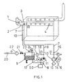
- Figure 1 shows a large 6-cylinder diesel engine of a ship.
- the engine is provided with a charger 1, which feeds pressurized combustion air into suction pipelines 2.
- the suction pipelines 2 are provided with a spray head 3, which is arranged to feed a mixture of gas and water mist into the suction manifold, wherefrom said mixture passes into the engine cylinders 4.
- the combustion temperature in the cylinders 4 decreases.
- the combustion temperature decreases efficiently both when the engine runs at full power and when it runs at partial power.
- the reason why the combustion temperature decreases efficiently also when the engine runs at partial power is that the spray head 3 also feeds gas into the suction pipelines.
- Gas feeding reduces the size of water drops, which is important, so that the water drops would vaporize easily and quickly also when the engine runs at partial power and its temperature is relatively low and the amount of water required for emission reduction is smaller than when the engine runs at full power. Thanks to the lowered combustion temperature nitrogen emissions are reduced efficiently throughout the entire power curve (curve showing power vs. rpm) of the engine.
- the gas feed solves the known problem of achieving sufficiently small drops, in particular, when the engine runs at partial power.
- the spray head 3 arranged in the suction pipelines 2 is shown enlarged.
- the spray head 3 comprises a plurality of nozzles 5, which allow an even feed of the mixture of gas and water mist into the suction pipelines 2.
- the number of nozzles 5 may vary. In principle, one nozzle may be sufficient.
- the spray head 3 is of the so-called twin liquid spray head type, into which gas and liquid are supplied separately, and the gas and the liquid mix inside the spray head prior to spraying the resulting mixture out through the nozzles 4 as mist.
- the gas supplied to the spray head 3 is air, and consequently the reference numeral 6 indicates a compressed-air compressor.
- the air is supplied along a pipe 7 into the spray head 3.
- the pressure can be 30 bar, for instance.
- the reference numeral 13 indicates an air pump, the reference numeral 14 indicates an electric motor, the reference numeral 15 indicates a filter and the reference numeral 16 indicates a back-pressure valve, which prevents the medium from being transferred from the pipe 7 into the pump 13.
- the liquid to be supplied into the spray head 3 is fresh water or aqueous liquid with a high water content.
- the water content is 95 to 100%, in which case values close the upper limits of the range are typically chosen.
- the liquid may contain anti-corrosive additives or a deliming agent.
- the fresh water is fed with a pump unit 8 from a container 9 along a pipe 10 to the spray head 3.
- the pump unit 8 comprises a piston pump 11 and an electric motor 12, whose operating speed can be controlled by control means, which are indicated by the reference numeral 50 in the figure.
- the control means 50 can be linked to react to the operating speed of the diesel engine.
- the reference numeral 17 indicates a back-pressure valve, which prevents the medium from being transferred from the spray head along the pipe 10 into the pump 11 or the container 9.
- the reference numerals 18 and 19 indicate a pipe and a release valve, respectively, through which the water can flow if the pressure of the pump 11 and in the pipe 18 exceed a given, predetermined limit value.
- the pipe 18 and the release valve 19 act as safety devices to prevent the pressure from rising so high that a component would get damaged.
- the reference numerals 20 and 21 indicate valves and the reference numeral 22 indicates a filter.
- the filter 22 prevents such particles that could block the spray head from entering the spray head 3.
- the diesel engine of Figure 1 operates such that when the diesel engine runs at a low power, both air and water is fed into the spray head 3. Most of the combustion air needed by the engine is fed through a charger 1 into the suction manifold. Air from the compressor 6 and water from the pump 11 mix in the spray head 3 and the spray head nozzles spray the mixture of air and water into the suction pipelines 2.
- the water is fine-grade mist with a droplet size of 200 micrometers at most, preferably less than 100 micrometers and more preferably less than 50 micrometers. Said drop size values indicate the size of all drops, and not an average size, for instance.
- the pump unit 8 can be controlled in a variety of ways, depending on the control means employed. One method is to make the operating speed of the pump 11 dependent on the operating speed of the diesel engine. The control methods are obvious to the person skilled in the art, and therefore they, or the pump control, will not be described in greater detail herein.
- the amount of water to be fed into the spray head 3 thus depends on the operating speed of the diesel engine and its momentary power. If the power is high, more water is fed. The amount of water to be fed is roughly 0.5 to 2.5 times the amount of fuel to be fed into the diesel engine.
- the amount of air to be fed into the spray head 3 is constant, or it does not change significantly according to the operating speed of the diesel engine when the diesel engine is run at partial power. Because of the above, the water content of the mixture sprayed from the spray head 3 decreases and the water drop size becomes smaller the lower the power by which the diesel engine is loaded.
- the drop size of aqueous mist can be selected so large that the water drops enter up to the cylinders 4, and they will not vaporize until inside the cylinders during the compression stroke. In vaporization, the compression work is reduced and it allows an improved operating efficiency of the diesel engine.
- a switch 23 opens a valve 21.
- a switch 24 closes the valve 21 when the water level in the container 9 has risen to a given level.
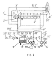
- Figure 2 shows a second embodiment of the apparatus according to the invention installed in the diesel engine.
- the solution of Figure 2 differs from the solution of Figure 1 such that the medium to be fed into a spray head 3' is heated (preheated).
- the heating is implemented such that a pipe 710' is arranged in a gas flowing space 31' in the exhaust manifold 30' of the diesel engine, where the hot, flowing exhaust gases release thermal energy to the medium, i.e. air/water mixture, flowing in the pipe 710'. Because the medium in the pipe 710' is preheated, the mixture sprayed from the spray head 3' does not cool the humid air to be fed into the engine excessively. Naturally, the level of preheating is adjusted according to the operating conditions.
- the gas flowing space 31' may comprise a hot water container, which is arranged to receive heat from the exhaust gases of the combustion engine.
- the embodiment of Figure 2 differs from the embodiment of Figure 1 also such that the air and the water to be fed into the spray head 3' are mixed prior to feeding into the spray head.
- the structure of the spray head 3' can be simpler than that of the spray head 3 in Figure 1. Mixing mainly takes place at point P', but mixing is still continued in a pipe portion 710 between the point P' and the spray head 3'.
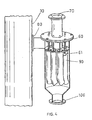
- Figure 4 shows a device for purifying exhaust gases by washing.
- the device is mounted in exhaust pipelines of the engine according to Figures 1 and 2.
- the reference numerals 61 indicate high-pressure spray heads, mounted in specific pipes 90, supported by a body 60, and spraying aqueous mist, which spray heads are operated at a pressure of 10 to 300 bar, preferably 20 to 100 bar.
- the nozzles of the spray heads 61 operate, they generate a suction that sucks exhaust gases.
- the aqueous mist and the nitrogen oxides from the exhaust gases react to produce nitric acid in the pipelines 90, which constitute reaction chambers.
- the purified i.e.
- the reaction products of the water mist and exhaust gases are discharged from a flange 100, from which the reaction products can be conducted away along a pipe (not shown).
- the device of Figure 4 is intended for mounting on a side of the exhaust manifold 30, 30' by means of a flange 80. Alternatively, the flange 80 can be omitted, and then the device is arranged inside the exhaust manifold so that the exhaust gases flow through the device.
- a baffle (not shown) which enables to adjust the ratio of how much of the exhaust gases are led into the flange 80 and how much are allowed to pass in the manifold 30. Washed exhaust gases flowing upwards in pipe 70 can through a pipe (not shown) be led back to the manifold 30 upstream of the flange 80 (and the baffle if such exists). Thanks to removing nitrogen oxides from the exhaust gases, the combination of the washing device of Figure 4 with the apparatus of Figures 1 and 2 results in a system by which the emissions, in particular, nitrogen oxide emissions are rendered very low. The apparatus of Figure 4 also reduces sulphur emissions substantially.
- the gas to be supplied into the spray head need not be air but it can be any other gas, for instance, washed exhaust gases originating from the engine. In the latter case, the temperature peaks of the engine will be lowered, because the specific heat of flue gases is higher than that of air, whereby the specific heat of the gas mixture fed from the spray head is higher.
- the number of nozzles in the spray head and the mutual angles and distances of the nozzles may vary from what is shown in Figure 3. In principle, there may be several spray heads 3, but it can be assumed that the invention will be most successfully implemented with one single spray head.
- the method and apparatus can also be applied to other engines than diesel engines: the method can thus be applied to Otto-cycle engines and gas turbines.
Landscapes
- Engineering & Computer Science (AREA)
- Chemical & Material Sciences (AREA)
- Combustion & Propulsion (AREA)
- Mechanical Engineering (AREA)
- General Engineering & Computer Science (AREA)
- Health & Medical Sciences (AREA)
- Public Health (AREA)
- Water Supply & Treatment (AREA)
- Biomedical Technology (AREA)
- Environmental & Geological Engineering (AREA)
- Analytical Chemistry (AREA)
- General Chemical & Material Sciences (AREA)
- Oil, Petroleum & Natural Gas (AREA)
- Chemical Kinetics & Catalysis (AREA)
- Exhaust Gas After Treatment (AREA)
- Output Control And Ontrol Of Special Type Engine (AREA)
- Separation Of Particles Using Liquids (AREA)
Claims (21)
- Verfahren zur Reinigung von Abgasen eines Kolbenmotors insbesondere eines Dieselmotors, wobei gemäß dem Verfahren feuchtes Gas in eine Brennkammer des Motors eingeleitet wird, wobei eine Mischung von Gas und wässrigem Nebel mit einem Sprühkopf (3, 3') in einen Raum (2, 2') eingespeist wird, der zu der Brennkammer führt, wobei das Mischungsverhältnis des Gases und des wässrigen Nebels in Abhängigkeit von Änderungen der Last des Verbrennungsmotors verändert wird, dadurch gekennzeichnet, dass das Mischungsverhältnis so geändert wird, dass der Anteil an dem wässrigen Nebel in der Mischung, während die Motorbelastung bis zu einem vorgegebenen Lastpegel ansteigt, erhöht wird, wobei der Motor mit einer Teilleistung läuft, und dass der Anteil an dem wässrigen Nebel in der Mischung verringert wird, während die Motorlast abnimmt, so dass der absolute Wasseranteil mit der Motorlast erhöht wird.
- Verfahren nach Anspruch 1, dadurch gekennzeichnet, dass, während die Motorbelastung den vorgegebenen Lastwert überschreitet, die Gaseinspeisung weitgehend unterbrochen wird, und die Einspeisung wässriger Flüssigkeit fortgesetzt wird, um den wässrigen Nebel aus dem Sprühkopf (3, 3') bereit zu stellen.
- Verfahren nach Anspruch 1, dadurch gekennzeichnet, dass das Gas und die wässrige Flüssigkeit zu einer Mischung vermischt werden, die dem Sprühkopf (3) zugeführt wird, um die Gas und wässrigen Nebel enthaltende Mischung zu erhalten.
- Verfahren nach Anspruch 1, dadurch gekennzeichnet, dass Gas und wässrige Flüssigkeit dem Sprühkopf (3') zugeführt werden, in dem das Gas und die Flüssigkeit miteinander vermischt werden, um die Mischung zu bekommen, die Gas und wässrigen Nebel enthält.
- Verfahren nach Anspruch 3 oder 4, dadurch gekennzeichnet, dass das Gas Luft ist.
- Verfahren nach Anspruch 5, dadurch gekennzeichnet, dass die Luft mittels eines Kompressors (6, 6') zugeführt wird, und dass die wässrige Flüssigkeit mittels einer Pumpe (11, 11') in den Sprühkopf (3, 3') eingebracht wird.
- Verfahren nach Anspruch 3 oder 4, dadurch gekennzeichnet, dass als Gas Abgase aus dem Verbrennungsmotor verwendet werden, die vor der Einspeisung in den Sprühkopf (3, 3') gewaschen werden.
- Verfahren nach Anspruch 7, dadurch gekennzeichnet, dass der wässrige Nebel in die Abgase gesprüht wird, um die Abgase zu waschen.
- Verfahren nach Anspruch 8, dadurch gekennzeichnet, dass der wässrige Nebel mit einem Druck zwischen 10 bis 300 Bar versprüht wird.
- Verfahren nach einem beliebigen der vorhergehenden Ansprüche, dadurch gekennzeichnet, dass ein Medium, das wässrige Flüssigkeit enthält, mittels der in den Motorabgasen enthaltenden Wärme vorgewärmt wird und in den Sprühkopf (3, 3') eingespeist wird und in den besagten Raum (2, 2') im Motor gesprüht wird.
- Verfahren nach Anspruch 1, dadurch gekennzeichnet, dass die Tropfengröße des wässrigen Nebels in der Mischung höchstens 200 µm beträgt.
- Verfahren zur Reinigung der Abgase eines Kolbenmotors nach Anspruch 1, dadurch gekennzeichnet, dass die Tropfengröße des wässrigen Nebels in der Mischung so groß ist, dass einige der Tropfen als solche in die Brennkammer eintreten und während des Verdichtungstakts darin verdunsten.
- Einrichtung zum Einspeisen von feuchtem Gas in einen Verbrennungsmotor, wobei zu der Einrichtung gehören: ein Sprühkopf (3, 3') zur Einspeisung von wässrigem Nebel in einen Raum (2, 2') in den Verbrennungsmotor, Gaseinspeisungsmittel (6, 6') zum Einspeisen von Gas in den Sprühkopf (3, 3'), Flüssigkeitseinspeisungsmittel (8, 8') zum Einspeisen von wässriger Flüssigkeit in den Sprühkopf und Vermischungsmittel (P'), um eine Mischung von Gas und wässrigem Nebel aus dem Sprühkopf in den Raum (2, 2') zu liefern, der dazu eingerichtet ist, strömungsmäßig mit der Brennkammer des Verbrennungsmotors verbunden zu sein und die Mischung von Gas und wässrigem Nebel in die Brennkammer zu liefern, und wobei die Einrichtung Steuermittel (50, 50') enthält, um die Einspeisungsmenge an wässriger Flüssigkeit aus dem Flüssigkeitseinspeisungsmittel (8, 8') zu steuern, und Steuermittel, um die Einspeisungsmenge des Gases aus dem Gaseinspeisungsmittel (6, 6') so zu steuern, dass das Mischungsverhältnis des einzuspeisenden Gases und des wässrigen Nebels in Abhängigkeit von Änderungen der Motorbelastung verändert werden können, dadurch gekennzeichnet, dass Steuermittel (50, 50') zum Steuern der Einspeisungsmenge der wässrigen Flüssigkeit dazu eingerichtet sind, die Einspeisungsmenge an wässriger Flüssigkeit in der Weise zu steigern, dass der Anteil an dem wässrigen Nebel in der Mischung erhöht wird, während die Motorlast auf einen vorgegebenen Lastpegel ansteigt, wobei der Motor mit einer Teilleistung läuft und der Anteil an wässrigem Nebel in der Mischung verringert wird, während die Motorlast abnimmt, so dass der Wasseranteil mit der Motorlast erhöht wird.
- Vorrichtung nach Anspruch 13, dadurch gekennzeichnet, dass das Gaseinspeisungsmittel einen Verdichter (6, 6') aufweist.
- Vorrichtung nach Anspruch 13 oder 14 mit einem Hochdrucksprühkopf (61) zum Einsprühen von wässrigem Nebel in die aus dem Verbrennungsmotor stammenden Abgase, um diese zu waschen, dadurch gekennzeichnet, dass das Gaseinspeisungsmittel Mittel (70) aufweist, um die gewaschenen Abgase in den Sprühkopf (3, 3') zu leiten.
- Vorrichtung nach Anspruch 13, dadurch gekennzeichnet, dass das Flüssigkeitseinspeisungsmittel eine Flüssigkeitsquelle (9, 9') und eine Pumpe (11, 11') zum Einspeisen der Flüssigkeit aus der Flüssigkeitsquelle in den Sprühkopf (3, 3') aufweisen.
- Vorrichtung nach Anspruch 16, dadurch gekennzeichnet, dass die Pumpe (11, 11') Steuermittel (50, 50') aufweist, um die Pumpendrehgeschwindigkeit zu erhöhen, wenn die Drehzahl des Verbrennungsmotors ansteigt, und die Pumpendrehzahl zu verringern, wenn die Drehzahl des Verbrennungsmotors abnimmt.
- Vorrichtung nach Anspruch 13, dadurch gekennzeichnet, dass die Vorrichtung ein Erwärmungsmittel (31') zum Erhitzen der in den Sprühkopf (3') einzuspeisenden wässrige Flüssigkeit aufweist.
- Vorrichtung nach Anspruch 18, dadurch gekennzeichnet, dass das Erwärmungsmittel auf einem Gasströmungsraum (31') basiert, der in dem Auslasskrümmer (30') des Verbrennungsmotors angeordnet ist, wobei die Quelle (9') der wässrigen Flüssigkeit dazu eingerichtet ist, die wässrige Flüssigkeit durch den Gasströmungsraum hindurch in den Sprühkopf (3') einzuspeisen, so dass die wässrige Flüssigkeit vor dem Einspeisen in den Sprühkopf (3') thermische Energie von den Abgasen aufnimmt.
- Vorrichtung nach Anspruch 13, dadurch gekennzeichnet, dass das Vermischungsmittel in dem Sprühkopf (3) angeordnet ist.
- Vorrichtung nach Anspruch 13, dadurch gekennzeichnet, dass die Vermischungsmittel (P') bezüglich der Strömungsrichtung der wässrigen Flüssigkeit stromaufwärts des Sprühkopfs (3') angeordnet sind.
Applications Claiming Priority (3)
| Application Number | Priority Date | Filing Date | Title |
|---|---|---|---|
| FI20010514A FI114112B (fi) | 2001-03-14 | 2001-03-14 | Menetelmä polttomoottorin pakokaasujen puhdistamiseksi ja laitteisto kostean ilman syöttämiseksi polttomoottoriin |
| FI20010514 | 2001-03-14 | ||
| PCT/FI2002/000199 WO2002073013A1 (en) | 2001-03-14 | 2002-03-13 | Method and apparatus for reducing combustion engine emissions |
Publications (2)
| Publication Number | Publication Date |
|---|---|
| EP1386069A1 EP1386069A1 (de) | 2004-02-04 |
| EP1386069B1 true EP1386069B1 (de) | 2007-10-10 |
Family
ID=8560743
Family Applications (1)
| Application Number | Title | Priority Date | Filing Date |
|---|---|---|---|
| EP02706794A Expired - Lifetime EP1386069B1 (de) | 2001-03-14 | 2002-03-13 | Verfahren und vorrichtung zur verringerung von verbrennungsmotoremissionen |
Country Status (15)
| Country | Link |
|---|---|
| US (1) | US7231893B2 (de) |
| EP (1) | EP1386069B1 (de) |
| JP (1) | JP4156928B2 (de) |
| KR (1) | KR100864328B1 (de) |
| CN (1) | CN100347424C (de) |
| AT (1) | ATE375442T1 (de) |
| AU (1) | AU2002240970B2 (de) |
| CA (1) | CA2439054A1 (de) |
| DE (1) | DE60222883T2 (de) |
| DK (1) | DK1386069T3 (de) |
| ES (1) | ES2294108T3 (de) |
| FI (1) | FI114112B (de) |
| NO (1) | NO20034039L (de) |
| RU (1) | RU2289704C2 (de) |
| WO (1) | WO2002073013A1 (de) |
Cited By (2)
| Publication number | Priority date | Publication date | Assignee | Title |
|---|---|---|---|---|
| DE102008061399A1 (de) | 2008-12-10 | 2010-06-17 | Man Diesel Se | Brennkraftmaschine mit zwei in Reihe geschalteten Abgasturboladern |
| DE102018123871A1 (de) * | 2018-09-27 | 2020-04-02 | Volkswagen Aktiengesellschaft | Mehrstufig aufgeladene Brennkraftmaschine mit Flüssigkeitseinspritzung in den Frischgasstrang zwischen zwei Verdichtern |
Families Citing this family (19)
| Publication number | Priority date | Publication date | Assignee | Title |
|---|---|---|---|---|
| JP4884690B2 (ja) * | 2005-04-11 | 2012-02-29 | 宇部興産機械株式会社 | 型内被覆成形用金型及び型内被覆成形方法 |
| FI119949B (fi) * | 2005-09-16 | 2009-05-15 | Waertsilae Finland Oy | Menetelmä turbokompressorilla varustetun mäntämoottorin yhteydessä |
| DE102005053495A1 (de) * | 2005-11-09 | 2006-12-28 | Siemens Ag | Vorrichtung und Verfahren zum Befeuchten der Ansaugluft bei Brennkraftmaschinen |
| DE102006054226A1 (de) * | 2006-11-15 | 2008-05-21 | Behr Gmbh & Co. Kg | Kraftfahrzeug und Verfahren zur Gewinnung und/oder Verwendung von Wasser |
| JP5484681B2 (ja) * | 2007-03-28 | 2014-05-07 | パナソニックヘルスケア株式会社 | 無菌環境維持装置 |
| DE102007048379A1 (de) * | 2007-10-09 | 2009-04-16 | Ralph Finger | Verbrennungsmotor, insbesondere Dieselmotor, mit Wasseremulsionsvoreinspritzung |
| JP5112991B2 (ja) * | 2008-08-27 | 2013-01-09 | 日野自動車株式会社 | NOx低減方法 |
| EP2449226B1 (de) | 2009-06-30 | 2019-03-06 | Cummins Power Generation IP, Inc. | Vorrichtungen, systeme und verfahren für verdampfungskühlung und feuchtkompression zur motorwärmeverwaltung |
| EP2918803A4 (de) * | 2012-09-19 | 2016-09-21 | Kawasaki Heavy Ind Ltd | Nassabscheidervorrichtung, motorsystem und schiff |
| DE102013003982A1 (de) * | 2013-03-10 | 2014-09-11 | Margret Spiegel | Angewandte Treibstoffe in der Zusammensetzung verändert zur Energiegewinnung anzuwenden. |
| JP6429335B2 (ja) | 2013-03-15 | 2018-11-28 | オーワイ ハルトン グループ リミテッド | 冷水噴霧システム制御方法及び排気換気システム |
| EP3018333B1 (de) * | 2013-06-28 | 2018-01-31 | Toyota Jidosha Kabushiki Kaisha | Steuerungsvorrichtung für verbrennungsmotor |
| CN103867345A (zh) * | 2014-04-02 | 2014-06-18 | 中国船舶重工集团公司第七一一研究所 | 一种船用柴油机的进气加湿系统 |
| EP3260187A1 (de) * | 2016-06-23 | 2017-12-27 | Yara Marine Technologies AS | System und verfahren zur reduzierung des volumens von schwefeloxiden in abgas |
| DE102016224543A1 (de) * | 2016-12-08 | 2018-06-14 | Bayerische Motoren Werke Aktiengesellschaft | Anordnung zur Kühlung von Luft |
| FR3064026B1 (fr) * | 2017-03-20 | 2019-03-22 | Flex Fuel-Energy Development (Ffed) | Amelioration d'une installation de nettoyage d'un moteur a combustion interne |
| FR3064025B1 (fr) * | 2017-03-20 | 2019-03-22 | Flex Fuel-Energy Development (Ffed) | Amelioration d'une installation de nettoyage d'un moteur a combustion interne |
| GB2560949B (en) | 2017-03-29 | 2020-03-18 | Ricardo Uk Ltd | Split cycle internal combustion engine |
| CN110630357B (zh) * | 2019-11-05 | 2021-10-08 | 尤洛卡(山东)矿业科技有限公司 | 一种防爆柴油机用尾气冷却净化水箱 |
Citations (1)
| Publication number | Priority date | Publication date | Assignee | Title |
|---|---|---|---|---|
| DE4230302A1 (de) * | 1992-09-10 | 1994-03-17 | Bosch Gmbh Robert | Einspritzvorrichtung für eine Brennkraftmaschine |
Family Cites Families (22)
| Publication number | Priority date | Publication date | Assignee | Title |
|---|---|---|---|---|
| US3930470A (en) * | 1974-01-30 | 1976-01-06 | Beverly Douglas | Vapor injection system for internal combustion engine |
| US4409931A (en) * | 1976-02-13 | 1983-10-18 | Owen, Wickersham & Erickson | Combustion and pollution control system |
| US4191134A (en) * | 1979-08-10 | 1980-03-04 | The Goodman Systems, Inc. | Fluid injection system and method for an internal combustion engine |
| US4300485A (en) * | 1980-03-03 | 1981-11-17 | The Goodman System Company, Inc. | Electronically controlled fluid injection system for an internal combustion engine |
| US4411224A (en) * | 1981-09-24 | 1983-10-25 | The Goodman System Company, Inc. | Fluid injection system for a turbocharged internal combustion engine |
| US4459943A (en) * | 1981-12-22 | 1984-07-17 | Goodman System Company, Inc. | Fluid injection system for an internal combustion engine responsive to fuel flow |
| US4442802A (en) * | 1982-10-01 | 1984-04-17 | Cook Earl H | Internal combustion engine water injector |
| US4958490A (en) * | 1986-09-08 | 1990-09-25 | Outokumpu Oy | Method for reducing nitric oxide emissions in exhaust gases from diesel engines |
| SU1401153A1 (ru) * | 1986-11-05 | 1988-06-07 | А. Е. Акимов, А. М. Белицкий и В.Г. Громов | Устройство дл подачи воздуха в двигатель внутреннего сгорани |
| AT400473B (de) * | 1989-08-03 | 1996-01-25 | Avl Verbrennungskraft Messtech | Brennkraftmaschine mit abgasturbolader |
| DK170218B1 (da) | 1993-06-04 | 1995-06-26 | Man B & W Diesel Gmbh | Stor trykladet dieselmotor |
| CN1164268A (zh) * | 1994-09-12 | 1997-11-05 | 恩瑟姆公司 | 缸内喷水发动机 |
| JP3784100B2 (ja) * | 1995-04-11 | 2006-06-07 | リード工業株式会社 | 内燃機関の吸入空気への噴霧装置 |
| DE19549142A1 (de) * | 1995-12-29 | 1997-07-03 | Asea Brown Boveri | Verfahren und Vorrichtung zur Nassreinigung des Düsenrings einer Abgasturbolader-Turbine |
| ATE215179T1 (de) * | 1996-09-09 | 2002-04-15 | Collin Consult Ab Lars | Antriebseinrichtung und verfahren zur reduktion der menge nox in den abgasen eines verbrennungsmotors |
| AU6312898A (en) * | 1998-03-02 | 1999-09-20 | Kvaerner Ships Equipment A/S | Apparatus for reducing contaminants in a pulsating exhaust gas |
| CN1156645C (zh) * | 1998-12-18 | 2004-07-07 | 刘海鹏 | 用水蒸气使燃料充分燃烧的装置 |
| FI112526B (fi) * | 1999-07-21 | 2003-12-15 | Waertsilae Finland Oy | Menetelmä nelitahtisen turboahdetun mäntämoottorin typpioksidipäästöjen (NOx) vähentämiseksi |
| US6240883B1 (en) * | 1999-07-23 | 2001-06-05 | Quantum Energy Technologies | Sub-critical water-fuel composition and combustion system |
| CN1276470A (zh) * | 2000-06-01 | 2000-12-13 | 石成山 | 机动车尾气过滤器 |
| US6578532B1 (en) * | 2002-01-23 | 2003-06-17 | Gerald W. Rowley | Fuel vaporizing and mixing system and method |
| US6732678B2 (en) * | 2002-06-17 | 2004-05-11 | Kuo Chang Lin | Apparatus and method for reproducing energy |
-
2001
- 2001-03-14 FI FI20010514A patent/FI114112B/fi active
-
2002
- 2002-03-13 JP JP2002572247A patent/JP4156928B2/ja not_active Expired - Fee Related
- 2002-03-13 CA CA002439054A patent/CA2439054A1/en not_active Abandoned
- 2002-03-13 ES ES02706794T patent/ES2294108T3/es not_active Expired - Lifetime
- 2002-03-13 RU RU2003130266/06A patent/RU2289704C2/ru active
- 2002-03-13 AU AU2002240970A patent/AU2002240970B2/en not_active Ceased
- 2002-03-13 AT AT02706794T patent/ATE375442T1/de not_active IP Right Cessation
- 2002-03-13 KR KR1020037011874A patent/KR100864328B1/ko not_active Expired - Fee Related
- 2002-03-13 EP EP02706794A patent/EP1386069B1/de not_active Expired - Lifetime
- 2002-03-13 CN CNB028064895A patent/CN100347424C/zh not_active Expired - Fee Related
- 2002-03-13 DK DK02706794T patent/DK1386069T3/da active
- 2002-03-13 WO PCT/FI2002/000199 patent/WO2002073013A1/en not_active Ceased
- 2002-03-13 US US10/468,702 patent/US7231893B2/en not_active Expired - Fee Related
- 2002-03-13 DE DE60222883T patent/DE60222883T2/de not_active Expired - Fee Related
-
2003
- 2003-09-12 NO NO20034039A patent/NO20034039L/no not_active Application Discontinuation
Patent Citations (1)
| Publication number | Priority date | Publication date | Assignee | Title |
|---|---|---|---|---|
| DE4230302A1 (de) * | 1992-09-10 | 1994-03-17 | Bosch Gmbh Robert | Einspritzvorrichtung für eine Brennkraftmaschine |
Cited By (3)
| Publication number | Priority date | Publication date | Assignee | Title |
|---|---|---|---|---|
| DE102008061399A1 (de) | 2008-12-10 | 2010-06-17 | Man Diesel Se | Brennkraftmaschine mit zwei in Reihe geschalteten Abgasturboladern |
| DE102018123871A1 (de) * | 2018-09-27 | 2020-04-02 | Volkswagen Aktiengesellschaft | Mehrstufig aufgeladene Brennkraftmaschine mit Flüssigkeitseinspritzung in den Frischgasstrang zwischen zwei Verdichtern |
| DE102018123871B4 (de) | 2018-09-27 | 2024-09-26 | Volkswagen Aktiengesellschaft | Mehrstufig aufgeladene Brennkraftmaschine mit Flüssigkeitseinspritzung in den Frischgasstrang zwischen zwei Verdichtern |
Also Published As
| Publication number | Publication date |
|---|---|
| CN1496441A (zh) | 2004-05-12 |
| DE60222883T2 (de) | 2008-02-07 |
| WO2002073013A1 (en) | 2002-09-19 |
| JP2004521227A (ja) | 2004-07-15 |
| FI20010514L (fi) | 2002-09-15 |
| FI114112B (fi) | 2004-08-13 |
| NO20034039L (no) | 2003-09-16 |
| RU2289704C2 (ru) | 2006-12-20 |
| FI20010514A0 (fi) | 2001-03-14 |
| RU2003130266A (ru) | 2005-04-10 |
| HK1059810A1 (en) | 2004-07-16 |
| KR20040005885A (ko) | 2004-01-16 |
| NO20034039D0 (no) | 2003-09-12 |
| CN100347424C (zh) | 2007-11-07 |
| US20040216699A1 (en) | 2004-11-04 |
| US7231893B2 (en) | 2007-06-19 |
| JP4156928B2 (ja) | 2008-09-24 |
| EP1386069A1 (de) | 2004-02-04 |
| AU2002240970B2 (en) | 2007-09-06 |
| CA2439054A1 (en) | 2002-09-19 |
| DE60222883D1 (de) | 2007-11-22 |
| DK1386069T3 (da) | 2008-02-11 |
| ATE375442T1 (de) | 2007-10-15 |
| ES2294108T3 (es) | 2008-04-01 |
| KR100864328B1 (ko) | 2008-10-17 |
Similar Documents
| Publication | Publication Date | Title |
|---|---|---|
| EP1386069B1 (de) | Verfahren und vorrichtung zur verringerung von verbrennungsmotoremissionen | |
| AU2002240970A1 (en) | Method and apparatus for reducing combustion engine emissions | |
| US5657630A (en) | Large supercharged diesel engine | |
| CN102341589B (zh) | 带有排气或者燃烧气体再循环的大型涡轮增压二冲程柴油发动机和用于减少NOx和碳烟排放的方法 | |
| US8327631B2 (en) | Air pollution control system for ocean-going vessels | |
| EP2525057B1 (de) | Abgas-denitrierungssystem, damit augestattetes schiff und verfahren zur steuerung des abgas-denitrierungssystems | |
| CN100447385C (zh) | 大型增压内燃发动机 | |
| US7225762B2 (en) | Spraying method and apparatus | |
| KR101671271B1 (ko) | 배기가스 정화기능을 갖는 대형 터보차지 2-행정 디젤 엔진 | |
| US20060266307A1 (en) | Emission control water injection system for diesel engines | |
| WO1998043732A1 (en) | REDUCING NOx EMISSIONS FROM AN ENGINE BY TEMPERATURE-CONTROLLED UREA INJECTION | |
| KR20210027095A (ko) | 선박용 엔진시스템 | |
| EP3519685A1 (de) | Mehrfachbankabgassystem mit vor einer turbine geschaltetem reduktionsmittelbereitstellungssystem | |
| HK1059810B (en) | Method and apparatus for reducing combustion engine emissions | |
| EP1924760B1 (de) | Anordnung und verfahren in verbindung mit einem kolbenmotor mit einem turboverdichter | |
| US20080196407A1 (en) | Method and an Arrangement in Connection with a Turbocharged Piston Engine | |
| JP2017180379A (ja) | エンジンシステム | |
| RU2199077C2 (ru) | Система дымопуска | |
| US7353782B2 (en) | Method and apparatus in a spraying apparatus |
Legal Events
| Date | Code | Title | Description |
|---|---|---|---|
| PUAI | Public reference made under article 153(3) epc to a published international application that has entered the european phase |
Free format text: ORIGINAL CODE: 0009012 |
|
| 17P | Request for examination filed |
Effective date: 20031009 |
|
| AK | Designated contracting states |
Kind code of ref document: A1 Designated state(s): AT BE CH CY DE DK ES FI FR GB GR IE IT LI LU MC NL PT SE TR |
|
| AX | Request for extension of the european patent |
Extension state: AL LT LV MK RO SI |
|
| REG | Reference to a national code |
Ref country code: HK Ref legal event code: DE Ref document number: 1059810 Country of ref document: HK |
|
| 17Q | First examination report despatched |
Effective date: 20060906 |
|
| GRAP | Despatch of communication of intention to grant a patent |
Free format text: ORIGINAL CODE: EPIDOSNIGR1 |
|
| GRAS | Grant fee paid |
Free format text: ORIGINAL CODE: EPIDOSNIGR3 |
|
| GRAA | (expected) grant |
Free format text: ORIGINAL CODE: 0009210 |
|
| AK | Designated contracting states |
Kind code of ref document: B1 Designated state(s): AT BE CH CY DE DK ES FI FR GB GR IE IT LI LU MC NL PT SE TR |
|
| RAP1 | Party data changed (applicant data changed or rights of an application transferred) |
Owner name: MARIOFF CORPORATION OY |
|
| REG | Reference to a national code |
Ref country code: GB Ref legal event code: FG4D |
|
| REG | Reference to a national code |
Ref country code: CH Ref legal event code: EP |
|
| REG | Reference to a national code |
Ref country code: IE Ref legal event code: FG4D |
|
| REF | Corresponds to: |
Ref document number: 60222883 Country of ref document: DE Date of ref document: 20071122 Kind code of ref document: P |
|
| REG | Reference to a national code |
Ref country code: SE Ref legal event code: TRGR |
|
| REG | Reference to a national code |
Ref country code: HK Ref legal event code: GR Ref document number: 1059810 Country of ref document: HK |
|
| REG | Reference to a national code |
Ref country code: DK Ref legal event code: T3 |
|
| ET | Fr: translation filed | ||
| NLV1 | Nl: lapsed or annulled due to failure to fulfill the requirements of art. 29p and 29m of the patents act | ||
| REG | Reference to a national code |
Ref country code: ES Ref legal event code: FG2A Ref document number: 2294108 Country of ref document: ES Kind code of ref document: T3 |
|
| PG25 | Lapsed in a contracting state [announced via postgrant information from national office to epo] |
Ref country code: LI Free format text: LAPSE BECAUSE OF FAILURE TO SUBMIT A TRANSLATION OF THE DESCRIPTION OR TO PAY THE FEE WITHIN THE PRESCRIBED TIME-LIMIT Effective date: 20071010 Ref country code: NL Free format text: LAPSE BECAUSE OF FAILURE TO SUBMIT A TRANSLATION OF THE DESCRIPTION OR TO PAY THE FEE WITHIN THE PRESCRIBED TIME-LIMIT Effective date: 20071010 Ref country code: CH Free format text: LAPSE BECAUSE OF FAILURE TO SUBMIT A TRANSLATION OF THE DESCRIPTION OR TO PAY THE FEE WITHIN THE PRESCRIBED TIME-LIMIT Effective date: 20071010 |
|
| REG | Reference to a national code |
Ref country code: CH Ref legal event code: PL |
|
| PG25 | Lapsed in a contracting state [announced via postgrant information from national office to epo] |
Ref country code: PT Free format text: LAPSE BECAUSE OF FAILURE TO SUBMIT A TRANSLATION OF THE DESCRIPTION OR TO PAY THE FEE WITHIN THE PRESCRIBED TIME-LIMIT Effective date: 20080310 |
|
| PLBE | No opposition filed within time limit |
Free format text: ORIGINAL CODE: 0009261 |
|
| STAA | Information on the status of an ep patent application or granted ep patent |
Free format text: STATUS: NO OPPOSITION FILED WITHIN TIME LIMIT |
|
| PG25 | Lapsed in a contracting state [announced via postgrant information from national office to epo] |
Ref country code: BE Free format text: LAPSE BECAUSE OF FAILURE TO SUBMIT A TRANSLATION OF THE DESCRIPTION OR TO PAY THE FEE WITHIN THE PRESCRIBED TIME-LIMIT Effective date: 20071010 |
|
| 26N | No opposition filed |
Effective date: 20080711 |
|
| PG25 | Lapsed in a contracting state [announced via postgrant information from national office to epo] |
Ref country code: MC Free format text: LAPSE BECAUSE OF NON-PAYMENT OF DUE FEES Effective date: 20080331 |
|
| PG25 | Lapsed in a contracting state [announced via postgrant information from national office to epo] |
Ref country code: IE Free format text: LAPSE BECAUSE OF NON-PAYMENT OF DUE FEES Effective date: 20080313 Ref country code: GR Free format text: LAPSE BECAUSE OF FAILURE TO SUBMIT A TRANSLATION OF THE DESCRIPTION OR TO PAY THE FEE WITHIN THE PRESCRIBED TIME-LIMIT Effective date: 20080111 |
|
| PG25 | Lapsed in a contracting state [announced via postgrant information from national office to epo] |
Ref country code: FI Free format text: LAPSE BECAUSE OF FAILURE TO SUBMIT A TRANSLATION OF THE DESCRIPTION OR TO PAY THE FEE WITHIN THE PRESCRIBED TIME-LIMIT Effective date: 20071010 |
|
| PGFP | Annual fee paid to national office [announced via postgrant information from national office to epo] |
Ref country code: AT Payment date: 20090325 Year of fee payment: 8 Ref country code: DK Payment date: 20090324 Year of fee payment: 8 Ref country code: ES Payment date: 20090324 Year of fee payment: 8 |
|
| PGFP | Annual fee paid to national office [announced via postgrant information from national office to epo] |
Ref country code: GB Payment date: 20090331 Year of fee payment: 8 |
|
| PG25 | Lapsed in a contracting state [announced via postgrant information from national office to epo] |
Ref country code: CY Free format text: LAPSE BECAUSE OF FAILURE TO SUBMIT A TRANSLATION OF THE DESCRIPTION OR TO PAY THE FEE WITHIN THE PRESCRIBED TIME-LIMIT Effective date: 20071010 |
|
| PGFP | Annual fee paid to national office [announced via postgrant information from national office to epo] |
Ref country code: DE Payment date: 20090324 Year of fee payment: 8 Ref country code: FR Payment date: 20090331 Year of fee payment: 8 Ref country code: IT Payment date: 20090319 Year of fee payment: 8 Ref country code: SE Payment date: 20090325 Year of fee payment: 8 |
|
| PG25 | Lapsed in a contracting state [announced via postgrant information from national office to epo] |
Ref country code: LU Free format text: LAPSE BECAUSE OF NON-PAYMENT OF DUE FEES Effective date: 20080313 |
|
| PG25 | Lapsed in a contracting state [announced via postgrant information from national office to epo] |
Ref country code: TR Free format text: LAPSE BECAUSE OF FAILURE TO SUBMIT A TRANSLATION OF THE DESCRIPTION OR TO PAY THE FEE WITHIN THE PRESCRIBED TIME-LIMIT Effective date: 20071010 |
|
| EUG | Se: european patent has lapsed | ||
| REG | Reference to a national code |
Ref country code: DK Ref legal event code: EBP |
|
| GBPC | Gb: european patent ceased through non-payment of renewal fee |
Effective date: 20100313 |
|
| PG25 | Lapsed in a contracting state [announced via postgrant information from national office to epo] |
Ref country code: AT Free format text: LAPSE BECAUSE OF NON-PAYMENT OF DUE FEES Effective date: 20100313 |
|
| REG | Reference to a national code |
Ref country code: FR Ref legal event code: ST Effective date: 20101130 |
|
| PG25 | Lapsed in a contracting state [announced via postgrant information from national office to epo] |
Ref country code: FR Free format text: LAPSE BECAUSE OF NON-PAYMENT OF DUE FEES Effective date: 20100331 |
|
| PG25 | Lapsed in a contracting state [announced via postgrant information from national office to epo] |
Ref country code: DE Free format text: LAPSE BECAUSE OF NON-PAYMENT OF DUE FEES Effective date: 20101001 |
|
| PG25 | Lapsed in a contracting state [announced via postgrant information from national office to epo] |
Ref country code: IT Free format text: LAPSE BECAUSE OF NON-PAYMENT OF DUE FEES Effective date: 20100313 Ref country code: GB Free format text: LAPSE BECAUSE OF NON-PAYMENT OF DUE FEES Effective date: 20100313 |
|
| REG | Reference to a national code |
Ref country code: ES Ref legal event code: FD2A Effective date: 20110415 |
|
| PG25 | Lapsed in a contracting state [announced via postgrant information from national office to epo] |
Ref country code: DK Free format text: LAPSE BECAUSE OF NON-PAYMENT OF DUE FEES Effective date: 20100331 |
|
| PG25 | Lapsed in a contracting state [announced via postgrant information from national office to epo] |
Ref country code: ES Free format text: LAPSE BECAUSE OF NON-PAYMENT OF DUE FEES Effective date: 20110404 |
|
| PG25 | Lapsed in a contracting state [announced via postgrant information from national office to epo] |
Ref country code: ES Free format text: LAPSE BECAUSE OF NON-PAYMENT OF DUE FEES Effective date: 20100314 |
|
| PG25 | Lapsed in a contracting state [announced via postgrant information from national office to epo] |
Ref country code: SE Free format text: LAPSE BECAUSE OF NON-PAYMENT OF DUE FEES Effective date: 20100314 |