EP1385325A1 - Cradle, security system, telephone, and monitoring method - Google Patents
Cradle, security system, telephone, and monitoring method Download PDFInfo
- Publication number
- EP1385325A1 EP1385325A1 EP02708765A EP02708765A EP1385325A1 EP 1385325 A1 EP1385325 A1 EP 1385325A1 EP 02708765 A EP02708765 A EP 02708765A EP 02708765 A EP02708765 A EP 02708765A EP 1385325 A1 EP1385325 A1 EP 1385325A1
- Authority
- EP
- European Patent Office
- Prior art keywords
- cradle
- sensor
- section
- telephone
- monitoring method
- Prior art date
- Legal status (The legal status is an assumption and is not a legal conclusion. Google has not performed a legal analysis and makes no representation as to the accuracy of the status listed.)
- Withdrawn
Links
Images






Classifications
-
- H—ELECTRICITY
- H04—ELECTRIC COMMUNICATION TECHNIQUE
- H04M—TELEPHONIC COMMUNICATION
- H04M1/00—Substation equipment, e.g. for use by subscribers
- H04M1/02—Constructional features of telephone sets
- H04M1/04—Supports for telephone transmitters or receivers
- H04M1/06—Hooks; Cradles
-
- G—PHYSICS
- G08—SIGNALLING
- G08B—SIGNALLING SYSTEMS, e.g. PERSONAL CALLING SYSTEMS; ORDER TELEGRAPHS; ALARM SYSTEMS
- G08B13/00—Burglar, theft or intruder alarms
- G08B13/18—Actuation by interference with heat, light, or radiation of shorter wavelength; Actuation by intruding sources of heat, light, or radiation of shorter wavelength
- G08B13/189—Actuation by interference with heat, light, or radiation of shorter wavelength; Actuation by intruding sources of heat, light, or radiation of shorter wavelength using passive radiation detection systems
- G08B13/194—Actuation by interference with heat, light, or radiation of shorter wavelength; Actuation by intruding sources of heat, light, or radiation of shorter wavelength using passive radiation detection systems using image scanning and comparing systems
- G08B13/196—Actuation by interference with heat, light, or radiation of shorter wavelength; Actuation by intruding sources of heat, light, or radiation of shorter wavelength using passive radiation detection systems using image scanning and comparing systems using television cameras
- G08B13/19617—Surveillance camera constructional details
- G08B13/1963—Arrangements allowing camera rotation to change view, e.g. pivoting camera, pan-tilt and zoom [PTZ]
-
- G—PHYSICS
- G08—SIGNALLING
- G08B—SIGNALLING SYSTEMS, e.g. PERSONAL CALLING SYSTEMS; ORDER TELEGRAPHS; ALARM SYSTEMS
- G08B13/00—Burglar, theft or intruder alarms
- G08B13/18—Actuation by interference with heat, light, or radiation of shorter wavelength; Actuation by intruding sources of heat, light, or radiation of shorter wavelength
- G08B13/189—Actuation by interference with heat, light, or radiation of shorter wavelength; Actuation by intruding sources of heat, light, or radiation of shorter wavelength using passive radiation detection systems
- G08B13/194—Actuation by interference with heat, light, or radiation of shorter wavelength; Actuation by intruding sources of heat, light, or radiation of shorter wavelength using passive radiation detection systems using image scanning and comparing systems
- G08B13/196—Actuation by interference with heat, light, or radiation of shorter wavelength; Actuation by intruding sources of heat, light, or radiation of shorter wavelength using passive radiation detection systems using image scanning and comparing systems using television cameras
- G08B13/19654—Details concerning communication with a camera
- G08B13/19658—Telephone systems used to communicate with a camera, e.g. PSTN, GSM, POTS
-
- G—PHYSICS
- G08—SIGNALLING
- G08B—SIGNALLING SYSTEMS, e.g. PERSONAL CALLING SYSTEMS; ORDER TELEGRAPHS; ALARM SYSTEMS
- G08B13/00—Burglar, theft or intruder alarms
- G08B13/18—Actuation by interference with heat, light, or radiation of shorter wavelength; Actuation by intruding sources of heat, light, or radiation of shorter wavelength
- G08B13/189—Actuation by interference with heat, light, or radiation of shorter wavelength; Actuation by intruding sources of heat, light, or radiation of shorter wavelength using passive radiation detection systems
- G08B13/194—Actuation by interference with heat, light, or radiation of shorter wavelength; Actuation by intruding sources of heat, light, or radiation of shorter wavelength using passive radiation detection systems using image scanning and comparing systems
- G08B13/196—Actuation by interference with heat, light, or radiation of shorter wavelength; Actuation by intruding sources of heat, light, or radiation of shorter wavelength using passive radiation detection systems using image scanning and comparing systems using television cameras
- G08B13/19697—Arrangements wherein non-video detectors generate an alarm themselves
-
- H—ELECTRICITY
- H04—ELECTRIC COMMUNICATION TECHNIQUE
- H04M—TELEPHONIC COMMUNICATION
- H04M11/00—Telephonic communication systems specially adapted for combination with other electrical systems
- H04M11/04—Telephonic communication systems specially adapted for combination with other electrical systems with alarm systems, e.g. fire, police or burglar alarm systems
-
- H—ELECTRICITY
- H04—ELECTRIC COMMUNICATION TECHNIQUE
- H04M—TELEPHONIC COMMUNICATION
- H04M19/00—Current supply arrangements for telephone systems
- H04M19/08—Current supply arrangements for telephone systems with current supply sources at the substations
Definitions
- the present invention relates to a telephone cradle which externally transmits report contents from various sensors through a mobile or other telephone; a security system consisting of such a cradle and a managing device; a telephone; and a monitoring method.
- a communications function to connect to a communications network such as the Internet, an imaging function for a camera; and a positioning function to obtain current position and related map information.
- the mobile telephone is usually mounted to a support called a cradle for storage purposes when it is not in use, for example, when the user is at home.
- a cradle for storage purposes when it is not in use, for example, when the user is at home.
- the function of the conventional mobile telephone cradle is limited to charging the mobile telephone.
- PDA Personal Digital Assistant
- the communications and imaging functions are indispensable in various security and home control systems. If the system is capable of effectively making use of the functions of the mobile telephone, the system is made simple and inexpensive and becomes equipped with a capability to provide sophisticated, information-related collaboration service.
- the present invention is conceived to address these issues and has an objective to provide a simple, but highly capable cradle which only requires the user to replace a mobile or other telephone on it; a security system including the cradle and a managing device; a telephone; and a monitoring method.
- a cradle according to the present invention is characterized in that it includes:
- the sensor sensing a state of a monitored area may refer to any given sensor including open/close sensors, fire sensors, various built-in sensors, infrared sensors, and CCD cameras.
- the open/close sensor is installed at various doors and windows including the main entrance for the purpose of sensing an intruder into a house.
- the fire sensor senses a smoking and unusual rise in temperature for the purpose of sensing a fire.
- the various built-in sensors are incorporated in lights, safes, air conditioners, refrigerators, and the like for the purpose of detecting a person in the house and an abnormality of various indoor facilities.
- Especially suitable for the present invention among the infrared sensors and the CCD cameras are those attached to a robot watchdog or house animal for the purpose of detecting a suspicious person hanging around a house.
- the connecting section provides an electrical connection between the cradle and the telephone.
- the cradle receives a report from the sensor sensing a state of the monitored area via the sensor communications section, and the transmission instructing section provides an instruction signal to the telephone via the connecting section to cause the telephone to externally transmit the report content.
- the user can input various information and setting instructions to the cradle by using the operation section on the telephone as a user interface.
- the user can also enjoy various functions of the telephone, including a Internet connecting function and imaging function.
- a wide range of functions including Internet connection and security services, are realized using a cradle, providing a safe deposition for a telephone, which has a simple arrangement with no long distance communications means or user interface included.
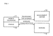
- FIG. 1 is a block diagram schematically showing an arrangement of the security system.
- the security system include a cradle 10 connected to a mobile telephone (telephone) 11; a management center (managing device) 13 which receives and manages information provided by the mobile telephone 11; and a sensor 12 which senses a state of a monitored area.
- the mobile telephone 11 and the management center 13 are linked to each other via a telephone communications network or the Internet.
- the cradle 10 and the sensor 12 are connected by short distance wireless communications (detailed later).
- FIG. 2 is a block diagram schematically showing an arrangement of the cradle 10.
- the cradle 10 includes a CPU (control processing unit; transmission instructing section, sensor instructing section) 20, a memory (detected information storage section) 21, an I/O (Input/Output) interface 22, a power supply circuit 23, a communications circuit (sensor communications section) 24, an antenna (sensor communications section) 25, a motor driving section (orientation altering means) 26, a motor (orientation altering means) 27, a mobile telephone detecting circuit 28, and a destruction sensor (destruction sensing section) 29.
- the memory 21, I/O interface 22, power supply circuit 23, communications circuit 24, motor driving section 26, mobile telephone detecting circuit 28, and destruction sensor 29 are connected to the CPU 20 via respective buses.
- the cradle 10 is housed in a housing made of molded resin or other material.
- the CPU 20 collects and processes information and gives instructions to various control circuits based on its computing function. Hence, the CPU 20 controls the entire cradle 10.
- the memory 21 is made up of a semiconductor memory such as a RAM (Random Access Memory) or a ROM (Read Only Memory); or an information storage device containing a recording medium such as a magnetic disk drive or an optical disc drive.
- the memory 21 stores various information under the control of the CPU 20.
- the memory 21 stores programs and data so that they are available for the CPU 20 to implement various kinds of control and computation.
- the I/O interface 22 is an interface circuit for data exchange with external devices under the control of the CPU 20.
- the I/O interface 22 is provided with various interface circuits and a connection connector to communicate with the mobile telephone 11.
- the power supply circuit 23 supplies electric power to the whole cradle 10 including the CPU 20, etc. and is made up of various transformer, stabilizer, and other circuits. In addition, the power supply circuit 23 has a charging function whereby the mobile telephone 11 is charged through the connector (detailed later).
- the communications circuit 24 and the antenna 25 are provided to enable the cradle 10 to perform short distance wireless communications (wireless communications) with, for example, the sensor 12.
- the communications circuit 24 and the antenna 25 operate by means of a weak radio wave over a 2.4-GHz (gigahertz), 11-Mbps LAN (Local Area Network) or Bluetooth (TM) standards whereby under normal conditions, communications are possible over a distance of about tens to hundreds of meters indoors.
- the motor driving section 26 and the motor 27 constitute drive means for changing the orientation of a camera mounted to a housing 30 for the mobile telephone 11 or the cradle 10 in accordance with a report content from the sensor 12 (detailed later).
- the motor driving section 26 is a circuit controlling the motor 27 under the control of the CPU 20.
- the mobile telephone detecting circuit 28 acts to detect the mobile telephone 11 replaced on the cradle 10, and includes circuitry receiving a detection signal from a detecting section 63 (detailed later). Only when the mobile telephone detecting circuit 28 detects the mobile telephone 11 being replaced, does the CPU 20 transmit/receive various signals and supply electric power through the I/O interface 22.
- the destruction sensor 29 includes a vibration sensor or a sound sensor to sense an assault or destructive act of an intruder on the cradle 10 through sensing of an abnormal vibration or sound.
- FIG 3 is a perspective view showing an example of the exterior of the housing for the cradle 10.
- the housing 30 has a hollow (telephone supporting section) 31 to support the mobile telephone 11.
- a connector connecting section, data retrieval section; not shown
- the connector is connected to the CPU 20 via the I / O interface 22 of the cradle 10.
- the connector is also responsible for transferring electric power from the power supply circuit 23 in the cradle 10 to the mobile telephone 11.
- the housing 30 can freely rotate in the horizontal direction as indicated by an arrow in the figure, by means of the motor driving section 26 and the motor 27 in the cradle 10.
- Figure 4 is a perspective view showing another example of the exterior of the housing for the cradle 10.
- the housing 40 in the figure has a camera section (imaging section) 42 and a rotational base 43 for the section 42, as well as a hollow 41 supporting the mobile telephone 11.
- the rotational base 43 can freely rotate in the horizontal direction by means of the motor driving section 26 and the motor 27 in the cradle 10, capable of changing the image capture direction for the camera section 42 by 360 degrees.
- the camera section 42 has an optical zoom function of which the zoom ratio controlled by the CPU 20 in the cradle 10.
- the CPU 20 can perform "digital zoom" on an image captured by the camera section 42 as part of image processing.
- a connector (not shown) providing electrical connection to the mobile telephone 11.
- Image data captured by the camera section 42 is sent to the mobile telephone 11 via the connector.
- FIG. 5 is a block diagram showing an internal arrangement of the housing 40.
- the figure uses the same reference numerals for common members as Figure 2 and omits descriptions thereof.
- the camera driving section 128 in Figure 5 is a circuit driving the camera section 42 under the control of the CPU 20.
- the camera driving section 128 instructs the camera section 42 on shoot timings, shot counts, resolution, and zoom settings and supplies drive power to the camera section 42.
- the motor 27 is connected to the rotational base 43, and the CPU 20 rotates the rotational base 43 to control the image capture direction of the camera section 42.
- Figure 6 is a perspective view showing yet another example of the exterior of the housing for the cradle 10.
- the housing 50 in the figure has a camera section 52 provided integrally with a fish-eye lens to achieve a 360-degre view in imaging, as well as a hollow 51 supporting the mobile telephone 11.
- the camera section 52 has also a correction circuit which corrects distortion of a captured image caused by the fish-eye lens by means of software.
- the housing in Figure 6 shares following common features with the one in Figure 4: the camera section 52 has various zoom functions, the bottom of the hollow 51 has a connector (not shown) to provide electrical connection to the mobile telephone 11, and image data captured by the camera section 52 is sent to the mobile telephone 11 via the connector.
- FIG. 7 is a block diagram showing an internal arrangement of the housing 50.
- the figure uses the same reference numerals for common members as Figures 2 and 5 and omits descriptions thereof.
- the camera driving section 110 in Figure 7 is a circuit driving the camera section 52 under the control of the CPU 20.
- the camera driving section 110 instructs the camera section 52 on shoot timings, shot counts, resolution, and zoom settings and supplies drive power to the camera section 52.
- the camera driving section 110 instructs the correction circuit in the camera section 52 on a correction process.
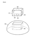
- Figure 8 is a perspective view showing a structure of connectors on a cradle housing.
- the hollow 61 has on the bottom a connector 62 shaped to couple with a connector on the mobile telephone 11: the connector 62 couples with a connector on the mobile telephone 11 to transmit/ receive various data and supply electric power while maintaining electrical connection.
- the hollow 61 has: a detecting section 63 detecting the replaced mobile telephone 11 through a key-shaped protrusion being pressed down; and a pair of press springs 64 firmly holding the mobile telephone 11.
- the press springs 64 hold the mobile telephone 11 and the detecting section 63 detects the mobile telephone 11.
- a result of the detection by the detecting section 63 is sent to the mobile telephone detecting circuit 28 in the cradle 10, triggering signal transmission/reception and electric power supply between the cradle 10 and the mobile telephone 11 through the connector 62.
- Figure 8 shows a structure where the housing 60 and the hollow 61 are separable. Hollow connectors 65, 66 are therefore provided to the housing 60 and the hollow 61 respectively, to ensure electrical connection between the two members.
- the connector 62 is not necessarily located on the bottom of the hollow 61: it may be located on a tip of a cable drawn out of the cradle 10. The arrangement allows the mobile telephone 11 to be placed beside to the housing.
- the housing of the cradle 10 is not necessarily formed as in Figures 3-8; it may take any shape, including those resembling an animal's or robot's hand, so that it suits design requirements and user tastes.
- the housing may send an animal sound or move the robot hand when the mobile telephone 11 is replaced on the cradle 10, which would attract the user's interest.
- FIG. 9 is a block diagram schematically showing an arrangement of a telephone.
- the mobile telephone 11 includes a CPU 70, a memory 71, an I / O interface 72, a mobile telephone high frequency circuit 73, a mobile telephone high frequency antenna 74, a short distance wireless circuit (cradle communications section) 75, a short distance wireless communications antenna 76, a DSP 77, a PCM codec 78, a speaker 79, a microphone 80, a camera section 81, a display section 82, and an operation section 83. These components are connected by buses with each other except the antenna and the user interface.
- the mobile telephone 11 is not only capable of a voice communications function, but also provides imaging, Internet connection, positioning, and music playback, and other many functions.
- the CPU 70 collects and processes information and gives instructions to various control circuits based on its computing function. Hence, the CPU 70 controls the entire mobile telephone 11.
- the memory 71 is made up of a semiconductor memory such as a RAM or a ROM; or an information storage device containing a recording medium such as a magnetic disk drive or an optical disc drive.
- the memory 71 stores various information under the control of the CPU 70.
- the memory 71 stores programs and data so that they are available for the CPU 70 to implement various kinds of control and computation.
- the I/O interface 72 is an interface circuit for data exchange with external device under the control of the CPU 70.
- the I/O interface 72 is provided with interface circuits and a connect connector to communicate with the cradle 10.
- the mobile telephone high frequency circuit 73 is a circuit oscillating at, and controlling, a high frequency for the communications between the mobile telephone 11 and a base station. Typically, the circuit 73 oscillates at a radio wave frequency of 800 MHz (megahertz) or 1.5 GHz (gigahertz). Using the radio wave, the mobile telephone 11 is capable of communications with a base station tens of kilometers away.
- the mobile telephone high frequency antenna 74 is a metal antenna for use in the oscillation at a radio wave frequency.
- the short distance wireless circuit 75 is a circuit for short distance wireless communications with the sensor 12 and the communications circuit 24 in the cradle 10, and operates by means of a weak radio wave over a 2.4-GHz (gigahertz) wireless LAN or Bluetooth whereby the mobile telephone 11 is capable of direct short distance wireless communications with the sensor 12 and the cradle 10.
- the short distance wireless communications antenna 76 is a metal antenna for use in the oscillation at a radio wave frequency.
- the DSP 77 is a digital signal processor and implements various digital signal processes under the control of the CPU 70.
- the PCM codec 78 is a circuit performing an encoding process converting a signal from analog to digital and a decoding process converting a signal from digital to analog.
- the PCM codec 78 converts an audio signal (analog signal) picked up by the microphone 80 to a digital signal for output to the DSP 77 and a digital signal from the DSP 77 to an audio signal for output to the speaker 79.
- the speaker 79 is adapted to receive an electrical audio signal input from the PCM codec 78 and produce actual sounds. The user can check the audio output from the mobile telephone 11 through the speaker 79.
- the microphone 80 is adapted to pickup the user's voice and sound and produce an electrical audio signal, allowing the user to talk at the microphone 80 to make a voice call through the mobile telephone 11.
- the camera section 81 includes a set of optical lenses, a CCD (Charge Coupled Device) camera, and a drive circuit for the camera.
- the camera section 81 captures an image by focusing light on the CCDs through the set of optical lenses.
- the camera section 81 has also a function of controlling the zoom ratio in imaging by adjusting the position of each optical lens.
- the display section 82 includes a dot matrix LCD (Liquid Crystal Display), but may be manufactured from any device, such as an LED (Light Emitting Diode) display, which is capable of displaying information to the user.
- a dot matrix LCD Liquid Crystal Display
- LED Light Emitting Diode
- the operation section 83 is a user interface with a keyboard including ten keys and a "+" key.
- the operation section 83 may be any of a variety of pointing and similar devices.
- the mobile telephone 11 of this kind is sold to users at a relatively low price and employed to provide, apart from voice calls, various services including packet-based data calls, music/game downloads, and "e-commerce".
- the sensor 12 consists of multiple sensors sensing a state of a monitored area. According to the present embodiment, they are installed various monitoring points both indoors and outdoors. As mentioned previously, the sensors 12 and the cradle 10 can perform short distance wireless communications, and require no complex wiring connecting numerous sensors 12, so that the sensors 12 can be readily installed and managed. Each sensor 12 has its unique ID (identification) number and sends the ID number to the cradle 10 so that the cradle 10 can identify the sensor 12.
- the sensors 12 may include a control circuit controlling the device to which the sensors 12 are attached, in addition to a simple state-sensing circuit.
- a control circuit controlling the device to which the sensors 12 are attached, in addition to a simple state-sensing circuit.
- it is preferably capable of controlling the power on/off of the light and the urgent lock for the safe and temperature settings for the air conditioner and refrigerator. This enables the cradle 10 to control various devices through the sensors 12, in addition to the reception of information from the sensors 12. As a result, a wide range of security and home control services become available.
- the sensors 12 Since communicating by means of weak radio wave, the sensors 12 have a simple and compact circuit arrangement and may be mounted to a wall, ceiling, or any other place.
- the sensors 12 are relatively low in power consumption and operate from, for example, a commercially available button-type battery for an extended period of time.
- the sensors 12 may include unique communications means: for example, they may be capable of connecting to the Internet or another communications network (external communications network) via a wired telephone link.
- Example of the sensors 12 include combinations of a personal computer and a short distance wireless communications interface (e.g. wireless LAN/Bluetooth card) and an Internet appliance terminal with an LCD, touch panel sensor, user interface, speaker, microphone, etc. all fitted in a single enclosure.
- the user of the mobile telephone 11 can readily connect to the Internet through the cradle 10 and the sensors 12 and collect various information. This means that the user can connect to the Internet, at or out of home, by operating the mobile telephone 11 alone.
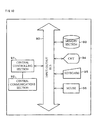
- FIG. 10 is a block diagram schematically showing an arrangement of a management center 13.
- the management center 13 has an input/output bus 90 as an interface through which a central controlling section (information managing means) 91 1 and a central communications section (information receiving means) 92 are connected to a memory section 93, CRT (Cathode Ray Tube) 94, keyboard 95, and mouse 96.
- a central controlling section information managing means
- a central communications section information receiving means
- the central controlling section 91 collects and processes information from home security systems, and also controls the management center 13.
- the central communications section 92 is adapted to communicate with the mobile telephone 11 and the cradle 10 under the control of the central controlling section 91, acting as an interface with the outside.
- the central communications section 92 may communicate directly with the mobile telephone 11, but normally via various telephone base stations.
- the memory section 93 includes a semiconductor memory (typically RAM or ROM) and various storage devices (typically magnetic disk drives and optical disc drives), and is adapted to store various information under the control of the central controlling section 91.
- the memory section 93 not only acts as a data base storing information transmitted from security systems, but also stores programs under which the central controlling section 91 performs various kinds of control and computation.
- the CRT 94, keyboard 95, and mouse 96 are a publicly known user interface. They are used for the manager to give various commands to the management center 13 and check/correct the record in the memory section 93. Various information is entered through the user interface and stored in the memory section 93.
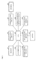
- Sensors 12a-12e are installed indoors/outdoors: 12a is an open/close sensor sensing a open/closed window 100, 12b is an open/close sensor sensing an open/closed main entrance door 101, 12c is a fire sensor sensing a smoking and an unusual rise in temperature in a room, 12d is a human body sensor sensing a person in a room using, for example, infrared, and 12e is a power on/off sensor, incorporated in a light, sensing the power on/off of the light.
- the sensor 12e has a special function of controlling the brightness and power on/off of the light.
- the mobile telephone 11 and the cradle 10 can not only detect the power on/off of the light, but also perform direct control of the light's operation.
- the user when at home, can turn on all lights (e.g., those installed at a main entrance and in a hallway and living room) either sequentially or all at once, by entering a command through the operation section 83 of the mobile telephone 11.
- the command for the operation of the lights may be entered in advance by the user to the mobile telephone 11 when he/ she is still out, and sent to the sensors 12 from the mobile telephone 11 through the cradle 10 when he/she replaces the mobile telephone 11 on the cradle 10 upon coming back home.
- appliances controlled by the sensors 12, other than the lights are air conditioners, refrigerators, safes, and various other devices and machines.
- the sensors 12 monitors a monitored area for any abnormalities (e.g., an open/closed door or window, and an indoor smoking) round the clock, and reports results of the monitoring to the cradle 10 regularly or immediately in the even of an abnormality occurrence by short distance wireless communications.
- any abnormalities e.g., an open/closed door or window, and an indoor smoking
- the CPU 20 in the cradle 10 Upon reception of the report from the sensors 12 through the communications circuit 24, the CPU 20 in the cradle 10 transfers the report data to the mobile telephone 11 through the I/O interface 22 and instructs the CPU 70 in the mobile telephone 11 to transmit the report data to the management center 13.
- the management center 13 Upon reception of the report data transmitted from the mobile telephone 11, the management center 13 stores the report data in the memory section 93 under the control of the central controlling section 91. The management center 13 informs the user or a security firm (service provider) of the content of the report data, to report the presence of an intruder.
- a security firm service provider
- the cradle 10 changes the orientation of the mobile telephone 11, by driving the motor driving section 26 and the motor 27 in accordance with the report content from the sensors 12. Specifically, the cradle 10 is rotated so that the microphone 80 and the camera section 81 in the mobile telephone 11 turn to the sensor 12 which has detected an abnormality, such as intrusion by a suspicious person or a quick rise in temperature.
- the sensor 12 preferably sends information (identified position information) on the position of the abnormality occurrence to the cradle 10.
- information identified position information
- the cradle 10 is rotated so that the microphone 80 and the camera section 81 in the mobile telephone 11 turn to the specific position of the abnormality occurrence, not to the sensor 12 which has detected an abnormality.
- the microphone 80 and the camera section 81 in the mobile telephone 11 turn to the specific position of the abnormality occurrence, not to the sensor 12 which has detected an abnormality.
- the CPU 20 in the cradle 10 can control the image zoom ratio of the camera section 81 by means of control data transmitted through the I/O interface 22.
- the sensor 12 is adapted to connect to the Internet or another external communications network, one can control the rotation of the cradle 10 and the image zoom ratio for the camera section 81 from out of the house.
- the CPU 20 in the cradle 10 preferably assumes that it is under attack and reports the situation to the management center 13 when the destruction sensor 29 has detected abnormal vibration or sound.
- the cradle 10 cannot send a direct report to the management center 13 in such an event, unless the cradle 10 is connected to the mobile telephone 11.
- the cradle 10 can however send a report indirectly in the following manner.
- the cradle 10 communicates with another cradle located nearby by short distance wireless communications through the communications circuit 24 and the antenna 25, to send the report to that cradle which will pass the report on to the management center 13 through the mobile telephone connected to it.
- the user with multiple cradles 10 can consolidate the communications traffic with the management center 13 by collecting information at one of the cradles 10.
- the cradle 10 cannot communicate with the management center 13, but can still communicate with a mobile telephone 11 nearby through a short distance wireless link.
- the cradle 10 can communicate with the mobile telephone 11, and the security system can provide the following services.
- the user launches application software on the mobile telephone 11 and enters a command to lock/unlock the main entrance door in advance through the operation section 83 while checking the display on the display section 82.
- a command may be entered to lock/unlock a back door, a garage shutter, a combination of them, or whatever the user likes.
- the garage shutter it is preferred if command are entered in advance not only to lock/unlock the shutter, but also to open/close it. Commands may be entered also to turn on/off lights in the garage.
- the mobile telephone 11 transfers the commands to the cradle 10 which in turn instructs the sensor 12b, controlling the lock/unlock of the main entrance door 101, to lock/unlock it.
- the sensor 12b is connected to a key unit including a movable section such as a solenoid.
- the key unit locks/unlocks according to an instruction from the sensor 12b.
- the sensor 12b preferably senses the lock/unlock state and sends a result of the sensing to the mobile telephone 11 or the management center 13 through the cradle 10.
- the user can visually confirm which door, shutter, etc. has failed to lock/unlock on the display section 82 of the mobile telephone 11.
- the cradle 10 is also capable of short distance wireless communications with sensors 12 which can connect to the Internet or a like network or a cradle located nearby, if any. This enables the cradle 10 to inform, for example, the management center 13 of the replacement of the mobile telephone 11 and whether the user is out or at home according to the communications state with the mobile telephone 11.
- the management center 13 can turn on the power supply to the air conditioner or turn on the power supply to Internet appliances to which sensors 12 are attached to present the user the latest news, a TV program schedule, notes from the family, and newly arrived e-mails messages.
- the cradle 10 assumes that it is being attacked and reports the situation to the management center 13 when the destruction sensor 29 in the cradle 10 senses abnormal vibration or sound. If the cradle 10 is not connected to the mobile telephone 11, the cradle 10 cannot make a direct report to the management center 13 through the mobile telephone 11.
- the cradle 10 can send the report to the management center 13 by short distance wireless communications with that sensor 12 or cradle.
- the CPU 20 in the cradle 10 preferably stores a content and the time of the abnormality sensed by the destruction sensor 29 in the memory 21, so that it can send the content from the memory 21 to the management center 13 later when the mobile telephone 11 is replaced in the cradle 10.
- the cradle 10 can also preferably report an abnormality, if detected at all, to the user by short distance wireless communications with the mobile telephone 11 right before he/she arrives at home. This enables the user to avoid a secondary case, for example, running into an intruder as he/she enters the house.
- the cradle 10, mobile telephone 11, and sensor 1 are installed in the residence of an old person (user) living alone, to detect and report open/close of the main entrance door, a person/persons in a room, open/close of a refrigerator, and use/non-use of miscellaneous household electrical appliances.
- the management center 13 can hence know the living conditions of the user by analyzing report data stored in the memory section 93.
- a sensor 12 may also be attached to a house animal robot or the like living with the user, to detect the user's reactions when the house animal robot is operated according to instructions from the management center 13 and the cradle 10.
- the management center 13 provides the information to the family of the user, a welfare services provider, or a local government. In this service example, it is the management center 13, not the cradle 10, that analyze report data in detail.
- the cradle 10 is therefore not required to include a microprocessor or the like which analyzes report data in detail. Hence, the user can be monitored using a cradle 10 with a relatively simple arrangement.
- the security system according to the present embodiment was aimed at house monitoring.
- the cradle 10 and the sensors 12 were supposed to be installed in a typical residential building; the present invention is not however limited to these applications.
- the cradle and the security system according to the present invention may be applied to monitoring of any given object including factories, warehouses, vehicles, trains, ships, shops, and other various facilities.
- the mobile telephone 11 has been typically kept in an independent holder or charger installed for use with the mobile telephone.
- the onboard terminal no longer needs a communications means to make a connection to the Internet. This simplifies the structure of the onboard terminal and reduces its cost. From the user's standpoint, with the cradle and the security system according to the present invention being applied to his/her mobile telephone, he/ she no longer needs to take the trouble to make a contract for, and maintain, a separate communications line solely for a onboard Internet link and vehicle monitoring.
- the user can enjoy onboard security services similar to those at home, by simply replacing the mobile telephone 11 on the cradle 10 when he/she boards the vehicle.
- the cradle 10 can inform the management center 13 that the user has alighted from the vehicle, according to a signal indicating lock/unlock of the door.
- the cradle according to the present invention includes:
- the monitoring method according to the present invention includes the steps of:
- the connecting section provides electrical connection between the cradle and the telephone.
- the cradle receives a report from the sensor sensing a state of the monitored area via the sensor communications section, and the transmission instructing section provides an instruction signal to the telephone via the connecting section to cause the telephone to externally transmit the report content.
- a wide range of functions including Internet connection and security services, are realized using a cradle, providing a safe deposition for a telephone, which has a simple arrangement with no long distance communications means or user interface included.
- the cradle according to the present invention may be arranged, in the cradle according to the arrangement, to further include a data retrieval section for retrieving data stored in the telephone via the connecting section.
- the monitoring method according to the present invention may be arranged, in the monitoring method according to the arrangement, to further including the step of retrieving data stored in the telephone via the connecting section.
- the cradle can retrieve various data stored in advance in the telephone via the connecting section. For example, the cradle retrieves command information entered to the telephone when the user is out of the house and data (e.g., voice call history) acquired by the telephone via a communications network such as a base station can make use of the acquired data.
- data e.g., voice call history
- the user enters instructions and settings for the cradle to the telephone in advance, for example, when he/ she is not at home and considers various telephone history information. Services can be provided which match the user's needs.
- the cradle according to the present invention may be arranged, in the cradle according to the arrangement, to further include an imaging section for capturing an image of the monitored area.
- the monitoring method according to the present invention may be arranged, in the monitoring method according to the arrangement, so that the state of the monitored area is sensed using an imaging section provided to the cradle for capturing an image of the monitored area.
- the cradle can capture an image of the monitored area even if the telephone does not include an imaging section.
- the imaging section of the cradle is not limited to digital cameras or other still imaging means, and may be various video cameras and other moving image capturing means.
- the cradle according to the present invention may be arranged, in the cradle according to the arrangement, so that the transmission instructing section controls an image zoom ratio for the imaging section.
- the monitoring method according to the present invention may be arranged, in the monitoring method according to the arrangement, so that an image zoom ratio for the imaging section is changed to scale up/down the image of the monitored area.
- the cradle can alter the zoom ratio for the imaging section. This enables the image of a suspicious place to scaled up/down for imaging with greater details.
- the cradle according to the present invention may be arranged, in the cradle according to the arrangement, to further include orientation altering means for altering orientation of at least either one of the telephone and the imaging section in accordance with the report content received by the sensor communications section.
- the monitoring method according to the present invention may be arranged, in the monitoring method according to the arrangement, to further include the step of altering orientation of at least either one of the telephone and the imaging section in accordance with the report content received by the sensor communications section.
- the orientation of the telephone refers specifically to the orientation of various sensors, such as a microphone and a camera, provided to the telephone.
- the orientation altering means may be any given arrangement including various motors and solenoids and other actuators.
- the arrangement for example, it becomes possible to identify a suspicious place from the report content received by the sensor communications section, and either to detect sound in the vicinity of the suspicious place with a microphone on the telephone or to capture an image of the vicinity with an imaging section of the telephone or the cradle.
- the cradle according to the present invention may be arranged, in the cradle according to the arrangement, to further include a destruction sensing section for sensing abnormal vibration or sound thereof as an event possibly leading to destruction.
- the monitoring method according to the present invention may be arranged, in the monitoring method according to the arrangement, to further include the step of sensing abnormal vibration or sound of the cradle as an event possibly leading to destruction.
- the cradle can sense an attack or a destructive act on the cradle from a suspicious person through abnormal vibration or sound.
- the cradle according to the present invention may be arranged, in the cradle according to the arrangement, to further include a sensor instructing section for transmitting, to the sensor, control instruction information for a device to which the sensor is attached.
- the monitoring method according to the present invention may be arranged, in the monitoring method according to the arrangement, to further include the step of transmitting, to the sensor, control instruction information for a device to which the sensor is attached.
- the sensor instructing section transmits, to the sensor, control instruction information for a device to which the sensor is attached.
- the sensor receiving it, can provide the control instruction information directly to the control section of the device according to the content of the control instruction information. Therefore, the control section of the device can control the device according to the control instruction information from the sensor.
- the cradle according to the present invention may be arranged, in the cradle according to the arrangement, so that the sensor communications section wirelessly communicates with the sensor.
- the monitoring method according to the present invention may be arranged, in the monitoring method according to the arrangement, so that the sensor communications section wirelessly communicates with the sensor.
- the cradle according to the present invention may be arranged, in the cradle according to the arrangement, so that the sensor connects to an external communications network.
- the monitoring method according to the present invention may be arranged, in the monitoring method according to the arrangement, so that the sensor connects to an external communications network.
- the senor connects to an external communications network such as the Internet. Therefore, if the telephone is not replaced on the cradle in an emergency, the cradle can externally send various reports via the sensor. In addition, the cradle and the sensor can collect various information over the external communications network.
- an external communications network such as the Internet.
- the cradle according to the present invention may be arranged, in the cradle accor ding to the arrangement, to further include a detected information storage section for storing a content of sensing by the sensor.
- the monitoring method according to the present invention may be arranged, in the monitoring method according to the arrangement, to further include the step of storing the content of sensing by the sensor.
- the content of sensing by the sensor can be stored if the cradle is not capable of external communication.
- the cradle can externally report the content of sensing by the sensor when the cradle is capable of external communications sometime later.
- the cradle according to the present invention may be arranged, in the cradle according to the arrangement, so that the sensor transmits, to the sensor communications section, identified position information on where an abnormality has occurred in the monitored area.
- the monitoring method according to the present invention may be arranged, in the monitoring method according to the arrangement, so that the sensor transmits, to the sensor communications section, identified position information on where an abnormality has occurred in the monitored area.
- the cradle can identify the position of the abnormality occurrence on the basis of the identified position information. This enables the above situations in the monitored area to be more specifically perceived.
- the telephone is preferably a mobile telephone.
- the telephone according to the present invention is however not limited to the mobile telephone, and may be, for example, the slave machine of a common cordless telephone set.
- the security system according to the present invention includes:
- information from the cradle inclusively refers to all information transmitted according to instructs of the cradle, from no matter which transmission means the information is transmitted, the telephone or the sensor.
- the information managing means can analyze information from the cradle in real time or afterwards. It therefore becomes possible to provide a wide range of information to the user and third parties.
- the telephone according to the present invention is arranged to include a cradle communications section for receiving the instruction signal from the transmission instructing section in a cradle according to any one of the arrangements.
- the telephone can receive an instruction signal from the cradle at the cradle communications section and externally transmit the report content from the sensor.
- a wide range of functions including Internet connection and security services, are realized using a cradle which has a simple arrangement with no long distance communications means or user interface included.
- the cradle according to the present invention can realize a wide range of functions, including Internet connection and security services, simply by replacing a telephone such as a mobile telephone, and is especially suited to the provision of security services to regular homes and the use as an onboard terminal.
Landscapes
- Engineering & Computer Science (AREA)
- Physics & Mathematics (AREA)
- General Physics & Mathematics (AREA)
- Signal Processing (AREA)
- Multimedia (AREA)
- Alarm Systems (AREA)
- Telephonic Communication Services (AREA)
- Telephone Function (AREA)
- Telephone Set Structure (AREA)
- Mobile Radio Communication Systems (AREA)
- Studio Devices (AREA)
Abstract
Description
Claims (26)
- A cradle, characterized in that it comprises:a telephone supporting section for supporting a telephone;a connecting section for electrically connecting to the telephone;a sensor communications section for receiving a report from a sensor sensing a state of a monitored area; anda transmission instructing section for providing an instruction signal to the telephone via the connecting section to cause to externally transmit a content of the report from the sensor.
- The cradle as defined in claim 1, further comprising: a data retrieval section for retrieving data stored in the telephone via the connecting section.
- The cradle as defined in either one of claims 1 and 2, further comprising an imaging section for capturing an image of the monitored area.
- The cradle as defined in claim 3, wherein
the transmission instructing section controls an image zoom ratio for the imaging section. - The cradle as defined in any one of claims 1 through 4, further comprising orientation altering means for altering orientation of at least either one of the telephone and the imaging section in accordance with the content of the report received by the sensor communications section.
- The cradle as defined in any one of claims 1 through 5, further comprising a destruction sensing section for sensing abnormal vibration or sound thereof as an event possibly leading to destruction.
- The cradle as defined in any one of claims 1 through 6, further comprising a sensor instructing section for transmitting, to the sensor, control instruction information for a device to which the sensor is attached.
- The cradle as defined in any one of claims 1 through 7, wherein
the sensor communications section wirelessly communicates with the sensor. - The cradle as defined in any one of claims 1 through 8, wherein
the sensor connects to an external communications network. - The cradle as defined in any one of claims 1 through 9, further comprising a detected information storage section for storing a content of sensing by the sensor.
- The cradle as defined in any one of claims 1 through 10, wherein
the sensor transmits, to the sensor communications section, identified position information on where an abnormality has occurred in the monitored area. - The cradle as defined in any one of claims 1 through 11, wherein
the telephone is a mobile telephone. - A security system, characterized in that it comprises:a cradle as defined in any one of claims 1 through 12; anda managing device including: information receiving means for receiving information from the cradle; and information managing means for managing the information received by the information receiving means.
- A telephone, characterized in that it comprises a cradle communications section for receiving the instruction signal from the transmission instructing section in a cradle as defined in any one of claims 1 through 12.
- A monitoring method, characterized in that it comprises the steps of:receiving, at a sensor communications section provided to a cradle, a report from a sensor sensing a state of a monitored area; andproviding an instruction signal to a telephone via a connecting section provided to the cradle for electrically connecting to the telephone, so as to externally transmit a content of the report from the sensor.
- The monitoring method as defined in claim 15, further comprising the step of retrieving data stored in the telephone via the connecting section.
- The monitoring method as defined in either one of claims 15 and 16, wherein
the state of the monitored area is sensed using an imaging section provided to the cradle for capturing an image of the monitored area. - The monitoring method as defined in claim 17, wherein
an image zoom ratio for the imaging section is changed to scale up/down the image of the monitored area. - The monitoring method as defined in any one of claims 15 through 18, further comprising the step of altering orientation of at least either one of the telephone and the imaging section in accordance with the content of the report received by the sensor communications section.
- The monitoring method as defined in any one of claims 15 through 19, further comprising the step of sensing abnormal vibration or sound of the cradle as an event possibly leading to destruction.
- The monitoring method as defined in any one of claims 15 through 20, further comprising the step of transmitting, to the sensor, control instruction information for a device to which the sensor is attached.
- The monitoring method as defined in any one of claims 15 through 21, wherein
the sensor communications section wirelessly communicates with the sensor. - The monitoring method as defined in any one of claims 15 through 22, wherein
the sensor connects to an external communications network. - The monitoring method as defined in any one of claims 15 through 23, further comprising the step of storing a content of sensing by the sensor.
- The monitoring method as defined in any one of claims 15 through 24, wherein
the sensor transmits, to the sensor communications section, identified position information on where an abnormality has occurred in the monitored area. - The monitoring method as defined in any one of claims 15 through 25, wherein
the telephone is a mobile telephone.
Applications Claiming Priority (3)
| Application Number | Priority Date | Filing Date | Title |
|---|---|---|---|
| JP2001105211 | 2001-04-03 | ||
| JP2001105211A JP3744375B2 (en) | 2001-04-03 | 2001-04-03 | Cradle, security system, mobile phone, and monitoring method |
| PCT/JP2002/003303 WO2002082795A1 (en) | 2001-04-03 | 2002-04-02 | Cradle, security system, telephone, and monitoring method |
Publications (2)
| Publication Number | Publication Date |
|---|---|
| EP1385325A1 true EP1385325A1 (en) | 2004-01-28 |
| EP1385325A4 EP1385325A4 (en) | 2004-06-23 |
Family
ID=18957936
Family Applications (1)
| Application Number | Title | Priority Date | Filing Date |
|---|---|---|---|
| EP02708765A Withdrawn EP1385325A4 (en) | 2001-04-03 | 2002-04-02 | Cradle, security system, telephone, and monitoring method |
Country Status (7)
| Country | Link |
|---|---|
| US (1) | US7209729B2 (en) |
| EP (1) | EP1385325A4 (en) |
| JP (1) | JP3744375B2 (en) |
| KR (1) | KR100592908B1 (en) |
| CN (1) | CN1500342A (en) |
| CA (1) | CA2443386C (en) |
| WO (1) | WO2002082795A1 (en) |
Cited By (5)
| Publication number | Priority date | Publication date | Assignee | Title |
|---|---|---|---|---|
| WO2006026978A1 (en) * | 2004-09-08 | 2006-03-16 | Paulussen Systems Gmbh | Video surveillance system and method for operating the same |
| DE102006048705A1 (en) * | 2006-10-14 | 2008-04-17 | Netgate Security-Produkte Gmbh | Device for telecommunications with alarm devices installed in security areas or the like. |
| EP1760899A4 (en) * | 2004-06-25 | 2013-01-09 | Sony Corp | WIRELESS COMMUNICATION SYSTEM, CRADLE UNIT AND MOBILE DEVICE |
| GB2502649A (en) * | 2012-06-01 | 2013-12-04 | Biisafe Oy | A stand for adjusting the alignment of a docked mobile electronics device and related camera view based on received input data |
| US9892628B2 (en) | 2014-10-14 | 2018-02-13 | Logitech Europe S.A. | Method of controlling an electronic device |
Families Citing this family (61)
| Publication number | Priority date | Publication date | Assignee | Title |
|---|---|---|---|---|
| JP2004220545A (en) * | 2003-03-03 | 2004-08-05 | Toshiaki Eto | Crime prevention system for multilayer window material and multilayer window material |
| US6983169B2 (en) * | 2003-03-14 | 2006-01-03 | Motorola, Inc. | Wireless device allowing for configuration of settings and method therefor |
| JP3838988B2 (en) | 2003-04-04 | 2006-10-25 | 埼玉日本電気株式会社 | Mobile phone equipment |
| KR100703435B1 (en) * | 2003-07-23 | 2007-04-03 | 삼성전자주식회사 | Stand for portable terminal with beam projector |
| JP2005103679A (en) * | 2003-09-29 | 2005-04-21 | Toshiba Corp | Robot equipment |
| JP2005103678A (en) * | 2003-09-29 | 2005-04-21 | Toshiba Corp | Robot equipment |
| JP4044504B2 (en) * | 2003-09-29 | 2008-02-06 | 株式会社東芝 | Cradle, high frequency receiving system and high frequency receiving method |
| US7089035B2 (en) * | 2003-10-28 | 2006-08-08 | Omron Corporation | Wireless operating system |
| US7551225B2 (en) * | 2003-12-09 | 2009-06-23 | Sony Ericsson Mobile Communications Ab | Positioning accessory for camera-equipped wireless terminals |
| US8732808B2 (en) * | 2004-09-08 | 2014-05-20 | Cradlepoint, Inc. | Data plan activation and modification |
| US9237102B2 (en) * | 2004-09-08 | 2016-01-12 | Cradlepoint, Inc. | Selecting a data path |
| US7764784B2 (en) * | 2004-09-08 | 2010-07-27 | Cradlepoint, Inc. | Handset cradle |
| US7962569B2 (en) | 2004-09-08 | 2011-06-14 | Cradlepoint, Inc. | Embedded DNS |
| US8249052B2 (en) * | 2004-09-08 | 2012-08-21 | Cradlepoint, Inc. | Automated access of an enhanced command set |
| US9232461B2 (en) * | 2004-09-08 | 2016-01-05 | Cradlepoint, Inc. | Hotspot communication limiter |
| US20070254727A1 (en) * | 2004-09-08 | 2007-11-01 | Pat Sewall | Hotspot Power Regulation |
| US8477639B2 (en) | 2004-09-08 | 2013-07-02 | Cradlepoint, Inc. | Communicating network status |
| US20090172658A1 (en) * | 2004-09-08 | 2009-07-02 | Steven Wood | Application installation |
| US9584406B2 (en) * | 2004-09-08 | 2017-02-28 | Cradlepoint, Inc. | Data path switching |
| US20060055790A1 (en) * | 2004-09-15 | 2006-03-16 | Longtek Electronics Co., Ltd. | Video camera remote fine-tuning installation |
| USD512041S1 (en) * | 2004-09-21 | 2005-11-29 | La Course Chirstopher M | Cell phone base station interface for LAN phones |
| USD524789S1 (en) * | 2005-03-03 | 2006-07-11 | General Instrument Corporation | Base for cordless telephone with answering device |
| USD524282S1 (en) * | 2005-03-03 | 2006-07-04 | General Instrument Corporation | Base for cordless telephone with answering device |
| US20060205384A1 (en) * | 2005-03-10 | 2006-09-14 | Chang Chih Y | Method of security monitoring and alarming using mobile voice device |
| US7649458B2 (en) * | 2005-04-07 | 2010-01-19 | Maria Mrazovich | Telephone messaging system with active security feature |
| US7720439B2 (en) * | 2005-07-28 | 2010-05-18 | D-Link Systems, Inc. | Wireless media device cradle |
| US20070139188A1 (en) * | 2005-12-15 | 2007-06-21 | General Instrument Corporation | Method and apparatus for communicating between a home network and a wireless network |
| US8825043B2 (en) * | 2006-01-04 | 2014-09-02 | Vtech Telecommunications Limited | Cordless phone system with integrated alarm and remote monitoring capability |
| US20070161372A1 (en) * | 2006-01-04 | 2007-07-12 | Gary Rogalski | Cordless phone system with integrated alarm & remote monitoring capability |
| KR100988736B1 (en) * | 2006-03-15 | 2010-10-20 | 삼성전자주식회사 | Home Network System and its Method for Shortest Path Movement of Autonomous Mobile Mobile Robot |
| US7482937B2 (en) * | 2006-03-24 | 2009-01-27 | Motorola, Inc. | Vision based alert system using portable device with camera |
| JP4745924B2 (en) * | 2006-08-30 | 2011-08-10 | キヤノン株式会社 | Cradle device and imaging device control method |
| US8265605B2 (en) * | 2007-02-06 | 2012-09-11 | Numerex Corp. | Service escrowed transportable wireless event reporting system |
| US8644272B2 (en) * | 2007-02-12 | 2014-02-04 | Cradlepoint, Inc. | Initiating router functions |
| US9021081B2 (en) * | 2007-02-12 | 2015-04-28 | Cradlepoint, Inc. | System and method for collecting individualized network usage data in a personal hotspot wireless network |
| US20120064949A1 (en) * | 2007-03-06 | 2012-03-15 | Kavounas Gregory T | I-ringer for personal electronic device |
| JP5265141B2 (en) * | 2007-06-15 | 2013-08-14 | オリンパス株式会社 | Portable electronic device, program and information storage medium |
| US20090111518A1 (en) * | 2007-10-29 | 2009-04-30 | Agere Systems Inc. | Interface for cellular and local non-cellular communications |
| WO2009064889A2 (en) * | 2007-11-14 | 2009-05-22 | Cradlepoint, Inc. | Configuring a wireless router |
| US20090129486A1 (en) * | 2007-11-15 | 2009-05-21 | Sequel Technologies, Llc. | Systems and methods for providing security communication procesess in a security system |
| JP2010086215A (en) * | 2008-09-30 | 2010-04-15 | Yupiteru Corp | Electronic apparatus, portable device used for the same, and cradle |
| EP2390855A4 (en) | 2009-01-22 | 2012-10-17 | Optex Co Ltd | Intrusion detection device |
| KR101555063B1 (en) | 2009-07-07 | 2015-09-23 | 삼성전자주식회사 | System and method for multi-screen mobile convergence service |
| KR101736863B1 (en) * | 2010-06-30 | 2017-05-17 | 엘지전자 주식회사 | Mobile terminal and terminal system having the same |
| JP2014505290A (en) * | 2010-12-21 | 2014-02-27 | インテル コーポレイション | Apparatus, system and method having a docking station |
| US8797175B2 (en) * | 2011-10-07 | 2014-08-05 | Htc Corporation | Electronic apparatus and sensory warning generating method thereof |
| WO2013065045A1 (en) * | 2011-10-31 | 2013-05-10 | Eyecue Vision Technologies Ltd | System for vision recognition based toys and games operated by a mobile device |
| KR101891768B1 (en) * | 2011-12-08 | 2018-08-24 | 삼성전자주식회사 | Device and method for alerting a state of wireless terminal |
| US8738080B2 (en) * | 2012-03-23 | 2014-05-27 | Sony Corporation | Docking station for android cellphone |
| US8774368B2 (en) * | 2012-06-08 | 2014-07-08 | Avaya Inc. | System and method to use enterprise communication systems to measure and control workplace noise |
| JP6089268B2 (en) * | 2012-09-07 | 2017-03-08 | パナソニックIpマネジメント株式会社 | Residential security system |
| US9445266B2 (en) * | 2012-09-25 | 2016-09-13 | Blackberry Limited | Smart plug or cradle |
| US20150133163A1 (en) * | 2013-02-21 | 2015-05-14 | Panasonic Intellectual Property Corporation Of America | Information notification method and information notification system |
| US20140362287A1 (en) * | 2013-06-10 | 2014-12-11 | Chien Fu CHUNG | Multi-directional positioning apparatus for mobile-phone camera shooting |
| JP2015026925A (en) * | 2013-07-25 | 2015-02-05 | 日本電信電話株式会社 | Sensor network system and cradle device |
| CN104135583A (en) * | 2014-07-14 | 2014-11-05 | 四川盟宝实业有限公司 | Infrared monitoring fitting of smart phone |
| US10119320B2 (en) | 2014-11-26 | 2018-11-06 | Menklab, LLC | Control system for providing cloud based commands for controlling operation of a moveable barrier |
| US9672670B2 (en) | 2014-11-26 | 2017-06-06 | Menklab, LLC | Control system for providing cloud based commands for controlling operation of a moveable barrier |
| JP6371228B2 (en) * | 2015-01-29 | 2018-08-08 | オムロンオートモーティブエレクトロニクス株式会社 | Biological data processing system, post-confirmation transmission device, control device, and charger used therefor |
| JP2019184167A (en) * | 2018-04-11 | 2019-10-24 | 東芝ライフスタイル株式会社 | Household electrical appliance, refrigerator |
| WO2022090678A1 (en) * | 2020-11-02 | 2022-05-05 | Securinet | Alert device for a person in a dangerous situation and its method of use by psychological conditioning |
Family Cites Families (41)
| Publication number | Priority date | Publication date | Assignee | Title |
|---|---|---|---|---|
| US4716582A (en) * | 1983-04-27 | 1987-12-29 | Phonetics, Inc. | Digital and synthesized speech alarm system |
| JPS6121162U (en) | 1984-07-13 | 1986-02-07 | 勝 杉田 | Phone stand that doubles as a security device |
| CA1277400C (en) | 1986-04-09 | 1990-12-04 | Uri Rapoport | Anti-theft and locating system |
| US4772875A (en) | 1986-05-16 | 1988-09-20 | Denning Mobile Robotics, Inc. | Intrusion detection system |
| US4868859A (en) * | 1987-06-12 | 1989-09-19 | Bt Telecom, Inc. | Supervised, interactive alarm reporting system |
| JPH0293862A (en) | 1988-09-30 | 1990-04-04 | Toshiba Corp | Record retrieving mechanism in network type data base |
| US5454024A (en) * | 1989-08-31 | 1995-09-26 | Lebowitz; Mayer M. | Cellular digital packet data (CDPD) network transmission system incorporating cellular link integrity monitoring |
| JPH0376499U (en) | 1989-11-27 | 1991-07-31 | ||
| US5103474A (en) * | 1990-05-08 | 1992-04-07 | Digital Products Corporation | Drive-by personnel monitoring system with radio link |
| US5134644A (en) * | 1990-08-17 | 1992-07-28 | Senses International | Data communication device |
| JP2741962B2 (en) | 1991-03-08 | 1998-04-22 | シャープ株式会社 | Control system using cordless telephone |
| US5309506A (en) * | 1991-10-25 | 1994-05-03 | Forerunner Corporation | Personal services telephone handset and system |
| US5568535A (en) * | 1992-06-01 | 1996-10-22 | Trackmobile, Inc. | Alarm system for enclosed area |
| USD345712S (en) * | 1993-02-11 | 1994-04-05 | Telestate International | Combined telephone and home security monitor |
| US5929752A (en) * | 1993-11-24 | 1999-07-27 | Trimble Navigation Limited | Clandestine missing vehicle location reporting using cellular channels |
| US6049273A (en) * | 1994-09-09 | 2000-04-11 | Tattletale Portable Alarm, Inc. | Cordless remote alarm transmission apparatus |
| US5873039A (en) * | 1994-11-28 | 1999-02-16 | Interonics Corporation | Cellular telephone-modem interface for data communication |
| US5745849A (en) * | 1996-02-09 | 1998-04-28 | Digital Monitoring Products, Inc. | Combination cordless telephone and premise-monitoring alarm system |
| US6049353A (en) * | 1996-05-17 | 2000-04-11 | Gray; Darrell D. | Computer network, processing of digitized, compressed, security camera video, intelligently onto hard drives of personal computers |
| JP2877207B2 (en) | 1996-10-23 | 1999-03-31 | 日本電気株式会社 | Satellite communication terminal with detachable handset cradle |
| US5933774A (en) * | 1996-10-31 | 1999-08-03 | Lucent Technologies Inc. | Location registering apparatus for use with a cellular telephone mobile station |
| US5991640A (en) | 1996-11-22 | 1999-11-23 | Ericsson Inc. | Docking and electrical interface for personal use communication devices |
| US6073004A (en) * | 1996-12-17 | 2000-06-06 | Ericsson Inc. | Emergency call initiator |
| DE69819221D1 (en) * | 1997-02-13 | 2003-12-04 | Monitoring Technologies Ltd | Alarm notification system |
| JP3460942B2 (en) * | 1998-01-22 | 2003-10-27 | 本田技研工業株式会社 | Control device for internal combustion engine |
| US6091771A (en) * | 1997-08-01 | 2000-07-18 | Wells Fargo Alarm Services, Inc. | Workstation for video security system |
| US5978684A (en) * | 1997-09-11 | 1999-11-02 | U S West, Inc. | Device for supporting multi-line configurations in a fixed wireless loop application |
| US5953650A (en) * | 1997-10-30 | 1999-09-14 | Motorola Inc. | Portable-mobile radiotelephone architecture and method for mobile personal security systems |
| GB2334412A (en) * | 1998-02-13 | 1999-08-18 | Nokia Mobile Phones Ltd | Mobile telephone with emergency responsive mode |
| JPH11284986A (en) | 1998-03-30 | 1999-10-15 | Victor Co Of Japan Ltd | Image transmission device |
| US6516314B1 (en) | 1998-11-17 | 2003-02-04 | Telefonaktiebolaget L M Ericsson (Publ) | Optimization of change log handling |
| US6263050B1 (en) * | 1998-12-18 | 2001-07-17 | Lucent Technologies Inc. | Method and system for responding to security system breaches via a wireless network |
| US6060994A (en) * | 1999-01-20 | 2000-05-09 | Tempa Communication Inc. | Method for controlling united home security system |
| US6215404B1 (en) * | 1999-03-24 | 2001-04-10 | Fernando Morales | Network audio-link fire alarm monitoring system and method |
| JP2000332820A (en) | 1999-05-18 | 2000-11-30 | Sony Corp | Network system and data transmission / reception method |
| JP4022342B2 (en) | 1999-06-07 | 2007-12-19 | 株式会社堀場製作所 | Communications system |
| JP2001069268A (en) * | 1999-08-27 | 2001-03-16 | Horiba Ltd | Communication device |
| US6452490B1 (en) * | 1999-08-24 | 2002-09-17 | Lucent Technologies Inc. | Home/commercial security monitoring system |
| JP2001076273A (en) | 1999-09-03 | 2001-03-23 | Toshiba Corp | Home security system |
| GB9922447D0 (en) | 1999-09-22 | 1999-11-24 | Clifford Roger | Portable alarm system |
| US6813505B2 (en) * | 2001-01-05 | 2004-11-02 | Skyworks Solutions, Inc. | Efficient and flexible communication device and system with base-to-base communication |
-
2001
- 2001-04-03 JP JP2001105211A patent/JP3744375B2/en not_active Expired - Fee Related
-
2002
- 2002-04-02 CA CA002443386A patent/CA2443386C/en not_active Expired - Fee Related
- 2002-04-02 CN CNA028077202A patent/CN1500342A/en active Pending
- 2002-04-02 KR KR1020037013019A patent/KR100592908B1/en not_active Expired - Fee Related
- 2002-04-02 EP EP02708765A patent/EP1385325A4/en not_active Withdrawn
- 2002-04-02 US US10/473,615 patent/US7209729B2/en not_active Expired - Fee Related
- 2002-04-02 WO PCT/JP2002/003303 patent/WO2002082795A1/en not_active Ceased
Cited By (5)
| Publication number | Priority date | Publication date | Assignee | Title |
|---|---|---|---|---|
| EP1760899A4 (en) * | 2004-06-25 | 2013-01-09 | Sony Corp | WIRELESS COMMUNICATION SYSTEM, CRADLE UNIT AND MOBILE DEVICE |
| WO2006026978A1 (en) * | 2004-09-08 | 2006-03-16 | Paulussen Systems Gmbh | Video surveillance system and method for operating the same |
| DE102006048705A1 (en) * | 2006-10-14 | 2008-04-17 | Netgate Security-Produkte Gmbh | Device for telecommunications with alarm devices installed in security areas or the like. |
| GB2502649A (en) * | 2012-06-01 | 2013-12-04 | Biisafe Oy | A stand for adjusting the alignment of a docked mobile electronics device and related camera view based on received input data |
| US9892628B2 (en) | 2014-10-14 | 2018-02-13 | Logitech Europe S.A. | Method of controlling an electronic device |
Also Published As
| Publication number | Publication date |
|---|---|
| KR20030088489A (en) | 2003-11-19 |
| US20040110544A1 (en) | 2004-06-10 |
| CN1500342A (en) | 2004-05-26 |
| JP2002305577A (en) | 2002-10-18 |
| US7209729B2 (en) | 2007-04-24 |
| WO2002082795A1 (en) | 2002-10-17 |
| CA2443386C (en) | 2008-09-30 |
| EP1385325A4 (en) | 2004-06-23 |
| JP3744375B2 (en) | 2006-02-08 |
| KR100592908B1 (en) | 2006-06-23 |
| CA2443386A1 (en) | 2002-10-17 |
Similar Documents
| Publication | Publication Date | Title |
|---|---|---|
| CA2443386C (en) | Cradle, security system, telephone, and monitoring method | |
| JP2002305577A5 (en) | ||
| US10819958B2 (en) | Home monitoring method and apparatus | |
| US20080266080A1 (en) | Wireless communication system | |
| US20070120978A1 (en) | Intelligent Sensory Platform for Wireless Two-Way Sensory Surveillance | |
| KR20090012542A (en) | Robot Home Monitoring System | |
| US20060022816A1 (en) | Home security system | |
| CA2316958A1 (en) | Personalized security system | |
| CN100512356C (en) | Central server of monitoring and controlling system for apartment building | |
| JP3915438B2 (en) | Remote monitoring system, remote monitoring method, remote monitoring program, and computer-readable recording medium recording the same | |
| JP3823814B2 (en) | Video surveillance system | |
| CN107102559A (en) | A kind of intelligent home control system and method | |
| KR20010109409A (en) | Method and system for controlling security by real time remote control using the internet | |
| JP4354206B2 (en) | Security system | |
| JP2006245829A (en) | Electric device control apparatus, electric device control system, electric device control method, electric device control program, and recording medium | |
| JP4931131B2 (en) | Security system | |
| US11341835B1 (en) | Security and safety monitor | |
| JP2003115085A (en) | Home security system | |
| JP4245954B2 (en) | Security system | |
| RU2303289C1 (en) | System for individual protection of real estate | |
| JP3679761B2 (en) | Remote management system | |
| JP2006243815A (en) | Security system | |
| KR100605135B1 (en) | Remote control device and method of home automation system | |
| EP3554067B1 (en) | Camera apparatus and communication system | |
| KR20040004971A (en) | System and method for notifying preservation alarm by using network |
Legal Events
| Date | Code | Title | Description |
|---|---|---|---|
| PUAI | Public reference made under article 153(3) epc to a published international application that has entered the european phase |
Free format text: ORIGINAL CODE: 0009012 |
|
| 17P | Request for examination filed |
Effective date: 20031015 |
|
| AK | Designated contracting states |
Kind code of ref document: A1 Designated state(s): AT BE CH CY DE DK ES FI FR GB GR IE IT LI LU MC NL PT SE TR |
|
| AX | Request for extension of the european patent |
Extension state: AL LT LV MK RO SI |
|
| A4 | Supplementary search report drawn up and despatched |
Effective date: 20040510 |
|
| RIC1 | Information provided on ipc code assigned before grant |
Ipc: 7H 04M 1/725 B Ipc: 7G 08B 25/10 B Ipc: 7H 04M 1/06 B Ipc: 7H 04M 11/04 A |
|
| 17Q | First examination report despatched |
Effective date: 20040804 |
|
| STAA | Information on the status of an ep patent application or granted ep patent |
Free format text: STATUS: THE APPLICATION IS DEEMED TO BE WITHDRAWN |
|
| 18D | Application deemed to be withdrawn |
Effective date: 20080103 |