EP1385253A1 - Hochgeschwindigkeitsrotor - Google Patents
Hochgeschwindigkeitsrotor Download PDFInfo
- Publication number
- EP1385253A1 EP1385253A1 EP02078061A EP02078061A EP1385253A1 EP 1385253 A1 EP1385253 A1 EP 1385253A1 EP 02078061 A EP02078061 A EP 02078061A EP 02078061 A EP02078061 A EP 02078061A EP 1385253 A1 EP1385253 A1 EP 1385253A1
- Authority
- EP
- European Patent Office
- Prior art keywords
- shaft
- speed rotor
- rotor according
- armor
- rotor
- Prior art date
- Legal status (The legal status is an assumption and is not a legal conclusion. Google has not performed a legal analysis and makes no representation as to the accuracy of the status listed.)
- Granted
Links
- 238000007789 sealing Methods 0.000 claims abstract description 10
- 239000000463 material Substances 0.000 claims abstract description 7
- 150000001875 compounds Chemical class 0.000 claims description 14
- 238000004519 manufacturing process Methods 0.000 claims description 7
- 229910052751 metal Inorganic materials 0.000 claims description 3
- 239000002184 metal Substances 0.000 claims description 3
- 229920003052 natural elastomer Polymers 0.000 claims description 2
- 229920001194 natural rubber Polymers 0.000 claims description 2
- 125000006850 spacer group Chemical group 0.000 claims description 2
- 229920003051 synthetic elastomer Polymers 0.000 claims description 2
- 239000005061 synthetic rubber Substances 0.000 claims description 2
- 238000000465 moulding Methods 0.000 description 9
- 239000000243 solution Substances 0.000 description 5
- 239000000919 ceramic Substances 0.000 description 4
- 238000000034 method Methods 0.000 description 4
- 238000009826 distribution Methods 0.000 description 2
- 238000010438 heat treatment Methods 0.000 description 2
- 238000001746 injection moulding Methods 0.000 description 2
- 239000000203 mixture Substances 0.000 description 2
- 230000036316 preload Effects 0.000 description 2
- 238000003860 storage Methods 0.000 description 2
- 229920003002 synthetic resin Polymers 0.000 description 2
- 239000000057 synthetic resin Substances 0.000 description 2
- OKTJSMMVPCPJKN-UHFFFAOYSA-N Carbon Chemical compound [C] OKTJSMMVPCPJKN-UHFFFAOYSA-N 0.000 description 1
- 229920000877 Melamine resin Polymers 0.000 description 1
- 239000004760 aramid Substances 0.000 description 1
- 229920003235 aromatic polyamide Polymers 0.000 description 1
- 229910052799 carbon Inorganic materials 0.000 description 1
- 239000004917 carbon fiber Substances 0.000 description 1
- 238000010276 construction Methods 0.000 description 1
- 238000001816 cooling Methods 0.000 description 1
- 238000006073 displacement reaction Methods 0.000 description 1
- 238000005485 electric heating Methods 0.000 description 1
- 239000003822 epoxy resin Substances 0.000 description 1
- 239000000835 fiber Substances 0.000 description 1
- 239000000945 filler Substances 0.000 description 1
- IVJISJACKSSFGE-UHFFFAOYSA-N formaldehyde;1,3,5-triazine-2,4,6-triamine Chemical compound O=C.NC1=NC(N)=NC(N)=N1 IVJISJACKSSFGE-UHFFFAOYSA-N 0.000 description 1
- SLGWESQGEUXWJQ-UHFFFAOYSA-N formaldehyde;phenol Chemical compound O=C.OC1=CC=CC=C1 SLGWESQGEUXWJQ-UHFFFAOYSA-N 0.000 description 1
- 239000011521 glass Substances 0.000 description 1
- 239000003365 glass fiber Substances 0.000 description 1
- 239000002241 glass-ceramic Substances 0.000 description 1
- 230000005484 gravity Effects 0.000 description 1
- 238000000227 grinding Methods 0.000 description 1
- 230000006698 induction Effects 0.000 description 1
- 239000003562 lightweight material Substances 0.000 description 1
- 230000005389 magnetism Effects 0.000 description 1
- 230000013011 mating Effects 0.000 description 1
- 239000004005 microsphere Substances 0.000 description 1
- 230000006855 networking Effects 0.000 description 1
- 229920001568 phenolic resin Polymers 0.000 description 1
- 239000004033 plastic Substances 0.000 description 1
- 229920000647 polyepoxide Polymers 0.000 description 1
- 238000004886 process control Methods 0.000 description 1
- 229910052761 rare earth metal Inorganic materials 0.000 description 1
- 150000002910 rare earth metals Chemical class 0.000 description 1
- 229920005989 resin Polymers 0.000 description 1
- 239000011347 resin Substances 0.000 description 1
- 230000035945 sensitivity Effects 0.000 description 1
- 238000005245 sintering Methods 0.000 description 1
- 238000009987 spinning Methods 0.000 description 1
- 239000007921 spray Substances 0.000 description 1
- 238000005507 spraying Methods 0.000 description 1
- 230000003068 static effect Effects 0.000 description 1
- 229920006305 unsaturated polyester Polymers 0.000 description 1
- 238000009736 wetting Methods 0.000 description 1
- 238000004804 winding Methods 0.000 description 1
Images
Classifications
-
- H—ELECTRICITY
- H02—GENERATION; CONVERSION OR DISTRIBUTION OF ELECTRIC POWER
- H02K—DYNAMO-ELECTRIC MACHINES
- H02K1/00—Details of the magnetic circuit
- H02K1/06—Details of the magnetic circuit characterised by the shape, form or construction
- H02K1/22—Rotating parts of the magnetic circuit
- H02K1/27—Rotor cores with permanent magnets
- H02K1/2706—Inner rotors
- H02K1/272—Inner rotors the magnetisation axis of the magnets being perpendicular to the rotor axis
- H02K1/274—Inner rotors the magnetisation axis of the magnets being perpendicular to the rotor axis the rotor consisting of two or more circumferentially positioned magnets
- H02K1/2753—Inner rotors the magnetisation axis of the magnets being perpendicular to the rotor axis the rotor consisting of two or more circumferentially positioned magnets the rotor consisting of magnets or groups of magnets arranged with alternating polarity
- H02K1/278—Surface mounted magnets; Inset magnets
Definitions
- the invention relates to a high-speed rotor, which is preferably designed as a permanent magnet rotor and from a wave with two shoulders, a number too this shaft lying axially parallel and on the circumference of this Wave distributed permanent magnet bars, as well as a die Permanent magnet rods enveloping cylinder jacket and one Filling the gaps of these parts, as well a method of assembling the parts into one stiff unity.
- Permanent magnet rotors of electrical machines which have been developed for the highest power density.
- Common features of such dynamoelectric machines which serve as generators on exhaust gas turbochargers, flywheel storage, or as motors for driving spinning turbines, centrifuges, or high-speed grinding spindles, are the high rotational speed of the rotors (n ⁇ 10 5 ) and their extreme stress due to the prevailing centrifugal forces.
- Contemporary permanent magnets have to be highly retentive, which means that they retain a lot of the magnetism they have gained after induction with an electromagnet. At the same time, they should be lighter than metal magnets to cause smaller centrifugal forces. For these reasons, the favorites are the permanent magnets made from rare earth metals by sintering.
- the design of the permanent magnet rotors has to ensure that the high impact sensitivity and the low tensile and torsional strength of the permanent magnets made of sintered ceramic are compensated by the use of a corset-like holder of the permanent magnets so that they are only subjected to pressure due to the centrifugal forces.
- the corset-like holder is preferably made of high-strength, lightweight and electrically and magnetically indifferent lightweight materials. Such materials are winding laminates with a high fiber content made of synthetic resin-impregnated aramid, carbon and glass fibers.
- Another problem with permanent magnet rotor design is that the surfaces of the permanent magnets made of ceramic cannot be joined or glued with synthetic resins. In other words; the use of permanent magnets made of ceramic requires a corset-like holder for the precise arrangement and positioning of these parts, so that the parts do not have to be glued.
- the object of the present invention is Further development of the permanent magnet rotors at the beginning described type, as well as the production of the modified Designs so that a new permanent magnet rotor with significantly increased operational reliability and increased Performance arises.
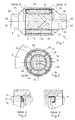
- the permanent magnet rotor 1 shown in FIG. 1 consists of the rotor shaft 2, the permanent magnet 3, the armor 4 and one into the cavities of the permanent magnet rotor 1 injected filling material, not shown.
- the Permanent magnet rotor 1 ends in the shaft ends 2a, 2b, from the shaft ends 2c, 2d to the shaft collar 2e, 2f are sufficient and for the inclusion of those not shown Serve storage of the permanent magnet rotor 1.
- To the Wave bundles 2e, 2f close the wave shoulders 2g and 2h, each consisting of a blunt cone cylindrical heel and a descending step consist.
- annular channel 2i for receiving the permanent magnets 3 and
- the bottom of the ring channel 2i is at least one recess 2j available with the radial feed channels 2k and Connection channel 2m is connected in the shaft axis.
- the Armor 4a either covers the shaft shoulder 2g, 2h or alternatively, the armor 4b is between the Shaft shoulder 2g and the shaft nut 2x coaxial to Rotor shaft 2 clamped.
- FIG. 2 shows a cross section of the permanent magnet rotor 1, the circular arrangement of the permanent magnets 3a-3d and the cavities that envelop the permanent magnets 3a-3d and through the ring channel 2i and the puncture 2j, with the radial feed channels 2k and the connecting channel 2m are communicatively connected.
- the segmented The permanent magnets 3a-3d are arranged by Intermediate pieces (5a-5d), which are made of electrical and magnetically indifferent materials, for example Glass ceramic, exist and preferably between the Wave shoulders 2g, 2h and the puncture 2j placed become.
- Figure 3 shows the detail A of Figure 1 and thus the Proposal to seal the joint with the Armor 4a and the wave shoulder 2g is given. It is a labyrinth seal that however, in contrast to the known type of lined up Grooves from at least two disk rings 7a, 7b consists.
- the disc rings 7a, 7b are on the armor 4a and on the shoulder of the shaft shoulder 2g (or as an analog Version not shown, on the armor 4b and one Heel of the shaft nut 2x) alternately centered and have spacer knobs 8 in places, so that they keep a distance from each other and from the shaft shoulder.
- With the prestressed sealing of the permanent magnet rotor 1 have the disc rings 7a, 7b of the advancing ones Filling the way.
- the changing resistance of the Filling compound around and between the disc rings 7a, 7b, 7n reduces the pressure of the filling compound so that the gap between the armor and the wave shoulder (Shaft nut) is filled.
- Figure 4 shows the detail B of Figure 1 and thus another proposal to seal the joint according to the task description of the Figure 3.
- a hardenable molding compound made of synthetic resin.
- Such molding compositions consist of epoxy resin or unsaturated polyester, but also from phenol-formaldehyde and melamine-formaldehyde, as well as a mixture of both.
- the spray pressure is 600 to 2500 bar.
- the one that can be achieved after the molding compound has hardened Preload is 600 to 1200 bar.
- fillers such as microspheres and Micro hollow spheres (10 - 200 ⁇ ) made of glass and ceramic with a volume fraction of the resin of 50%.
- the cavities of the permanent magnet rotor 1 are with the Molding compound through the connection channel 2m and from it branched supply channels 2k of the rotor shaft 2, according to the Figures 1 and 2, on the puncture 2j and the ring channel 2i to the segments of the permanent magnets 3a to 3c, to and with for wetting the inner surface of the armor 4a, 4b filled.
- the cavities escape during this process filling air through the joints (the armor 4a, 4b with the shaft shoulders 2g, 2h or shaft nut 2x), or is caused by the high pressure of the molding compound Imperceptibility compressed.
- the rheological can be solved by thermal measures Behavior of the molding compound in the injection molding process control appropriately.
- Local cooling with Peltier elements, for example Removal of excess friction and process heat and thus the delay in the curing of the filling compound.
- locally heating the joints for example with electric heating mats, can be partial networking the filling mass and thus the density Critical joints closed become.
Landscapes
- Engineering & Computer Science (AREA)
- Power Engineering (AREA)
- Permanent Field Magnets Of Synchronous Machinery (AREA)
- Iron Core Of Rotating Electric Machines (AREA)
- Rotary Pumps (AREA)
Abstract
Description
- Fig. 1
- zeigt den neuen Dauermagnetrotor mit verschiedenen Detaillösungen, in teilweisem Längsschnitt.
- Fig. 2
- zeigt den Querschnitt des in der Fig.1 gezeigten Dauermagnetrotors und die Verwendung einer Vorrichtung zu seinem zentrierten Zusammenbau.
- Fig. 3
- zeigt eine dynamische Labyrinthdichtung der Rotorpanzerung (Detail A der Fig. 1).
- Fig. 4
- zeigt eine elastisch-plastische Dichtung der Rotorpanzerung (Detail B der Fig. 1).
Claims (11)
- Hochgeschwindigkeitsrotor, insbesondere Dauermagnetrotor (1) für dynamoelektrische Maschinen hoher Leistungsdichte, bestehend mindestens aus einer Welle (2) und einem zur Welle (2) koaxialen Zylindermantel (4), sowie einer Anzahl Körpern (3) die zwischen der Welle (2) und dem Zylindermantel (4) verteilt sind, dadurch gekennzeichnet, dass zur vorgespannten Versiegelung und steifen Verbindung dieser Teile (1, 2, 3, 4) eine zwischenraumfüllende, komprimiert ausgehärtete Füllmasse dient.
- Hochgeschwindigkeitsrotor nach Anspruch 1, dadurch gekennzeichnet, dass die Welle (2) mindestens eine Wellenschulter (2g, 2h) und/oder mindestens eine Wellenmutter (2x) und mindestens einen Ringkanal (2i) der zwischen der Wellenschulter (2g,2h) und/oder der Wellenmutter (2x) liegt sowie mindestens einen Zufuhrkanal (2m) für die Zuleitung der Füllmasse aufweist.
- Hochgeschwindigkeitsrotor nach den Ansprüchen 1 und 2 dadurch gekennzeichnet, dass der Zufuhrkanal (2m) der Welle (2) mit vorzugsweise symmetrisch verteilten Zufuhrkanälen (2k) und mit mindestens einem Einstich (2j) der Welle (2) verbunden ist.
- Hochgeschwindigkeitsrotor nach den Ansprüchen 1 bis 3 dadurch gekennzeichnet, dass zwischen der Wellenschulter (2g, 2h) und/oder Wellenmutter (2x) ein Ringkanal (2i) liegt, der zur Aufnahme der Dauermagnete (3, 3a bis 3c) dient, und dass zur segmentierten Platzierung der Dauermagnete (3a bis 3c) Zwischenstücke (5a bis 5d) aus elektrisch und magnetisch indifferenten Werkstoffen verwendet werden.
- Hochgeschwindigkeitsrotor nach den Ansprüchen 1 bis 4 dadurch gekennzeichnet, dass sich auf den Wellenschultern (2g, 2h) eine zylinderschalenförmige Panzerung (4a) befindet.
- Hochgeschwindigkeitsrotor nach den Ansprüchen 1 bis 4 dadurch gekennzeichnet, dass die zylinderschalenförmige Panzerung (4b) zwischen zwei Wellenmuttern (2x) oder einer Wellenschulter (2g) und einer Wellenmutter (2x) gespannt wird.
- Hochgeschwindigkeitsrotor nach den Ansprüchen 1 bis 6 dadurch gekennzeichnet, dass zur Abdichtung der Berührungsstellen der Welle (2, 2g, 2h, 2x) und der Panzerung (4a, 4b) aussen- und innenzentrierende Scheibenringe (7a, 7b) vorzugsweise mit Distanznoppen (8) verwendet werden.
- Hochgeschwindigkeitsrotor nach den Ansprüchen 1 bis 6 dadurch gekennzeichnet, dass zur Abdichtung der Berührungsstellen der Welle (2, 2g, 2h, 2x) und der Panzerung (4a, 4b) eine mit Metallblech versteifte Manschette mit Dichtlippen aus Natur- oder Kunstkautschuk (9) verwendet wird.
- Verfahren zur Herstellung eines Hochgeschwindigkeitsrotors nach den Ansprüchen 1 bis 8 dadurch gekennzeichnet, dass zur Beschränkung der asymmetrischen Aufweitung der Panzerung (4a, 4b) der Rotor (1) in einen vorzugsweise durch die Rotorwelle (2) geführten Zentrierring (6) gelegt wird.
- Verfahren zur Herstellung eines Hochgeschwindigkeitsrotors nach den Ansprüchen 1 bis 9 dadurch gekennzeichnet, dass der Rotor (1) stellenweise thermisch behandelt wird.
- Verfahren zur Herstellung eines Hochgeschwindigkeitsrotors nach den Ansprüchen 1 bis 10 dadurch gekennzeichnet, dass der Rotor (1) durch gezieltes Abtragen von Massenteilen statisch und dynamisch ausgewuchtet wird.
Priority Applications (4)
| Application Number | Priority Date | Filing Date | Title |
|---|---|---|---|
| AT02078061T ATE418809T1 (de) | 2002-07-26 | 2002-07-26 | Hochgeschwindigkeitsrotor |
| DE50213151T DE50213151D1 (de) | 2002-07-26 | 2002-07-26 | Hochgeschwindigkeitsrotor |
| EP02078061A EP1385253B1 (de) | 2002-07-26 | 2002-07-26 | Hochgeschwindigkeitsrotor |
| US10/628,046 US6940196B2 (en) | 2002-07-26 | 2003-07-25 | High-speed rotor |
Applications Claiming Priority (1)
| Application Number | Priority Date | Filing Date | Title |
|---|---|---|---|
| EP02078061A EP1385253B1 (de) | 2002-07-26 | 2002-07-26 | Hochgeschwindigkeitsrotor |
Publications (2)
| Publication Number | Publication Date |
|---|---|
| EP1385253A1 true EP1385253A1 (de) | 2004-01-28 |
| EP1385253B1 EP1385253B1 (de) | 2008-12-24 |
Family
ID=29797268
Family Applications (1)
| Application Number | Title | Priority Date | Filing Date |
|---|---|---|---|
| EP02078061A Expired - Lifetime EP1385253B1 (de) | 2002-07-26 | 2002-07-26 | Hochgeschwindigkeitsrotor |
Country Status (4)
| Country | Link |
|---|---|
| US (1) | US6940196B2 (de) |
| EP (1) | EP1385253B1 (de) |
| AT (1) | ATE418809T1 (de) |
| DE (1) | DE50213151D1 (de) |
Cited By (4)
| Publication number | Priority date | Publication date | Assignee | Title |
|---|---|---|---|---|
| DE10341540A1 (de) * | 2003-09-09 | 2005-03-31 | Siemens Ag | Motor mit Außenläufer |
| EP2677133A1 (de) * | 2012-06-22 | 2013-12-25 | Skf Magnetic Mechatronics | Turbolader mit eingebetteter elektrischer Maschine mit Gleichstrom-Magnetspule |
| DE102018009845A1 (de) | 2018-12-14 | 2019-06-27 | Daimler Ag | Rotor für eine elektrische Maschine, insbesondere eines Kraftfahrzeugs |
| WO2022225990A1 (en) * | 2021-04-23 | 2022-10-27 | Albany Engineered Composites, Inc. | Process for applying fiber-reinforced plastic sleeves |
Families Citing this family (10)
| Publication number | Priority date | Publication date | Assignee | Title |
|---|---|---|---|---|
| US7052183B2 (en) * | 2004-06-15 | 2006-05-30 | Honeywell International Inc. | Composite resilient mount |
| CN1797904A (zh) * | 2004-12-20 | 2006-07-05 | 晋裕工业股份有限公司 | 凸形永磁转子马达 |
| US7504754B2 (en) * | 2005-10-31 | 2009-03-17 | Caterpillar Inc. | Rotor having multiple permanent-magnet pieces in a cavity |
| US7436095B2 (en) * | 2005-10-31 | 2008-10-14 | Caterpillar Inc. | Rotary electric machine |
| US7436096B2 (en) * | 2005-10-31 | 2008-10-14 | Caterpillar Inc. | Rotor having permanent magnets and axialy-extending channels |
| JP5193873B2 (ja) * | 2006-10-17 | 2013-05-08 | 山洋電気株式会社 | モータ用回転子及びその製造方法 |
| ATE498061T1 (de) * | 2007-05-24 | 2011-02-15 | Lindenmaier Gmbh | Turbolader |
| JP5980874B2 (ja) * | 2014-10-20 | 2016-08-31 | ファナック株式会社 | 回転電機に使用される磁石保持部材、回転子、回転電機および工作機械 |
| DE112020001824T5 (de) * | 2019-04-10 | 2021-12-23 | Ihi Corporation | Motorrotor |
| CN112179139B (zh) * | 2020-09-29 | 2023-10-24 | 镇江瑞昊工程塑料有限公司 | 一种烘箱烧结炉分批上料装置 |
Citations (6)
| Publication number | Priority date | Publication date | Assignee | Title |
|---|---|---|---|---|
| DE3622231A1 (de) * | 1986-07-02 | 1988-01-07 | Bosch Gmbh Robert | Permanentmagnetrotor fuer elektrische maschinen |
| JPH0374151A (ja) * | 1989-08-10 | 1991-03-28 | Aichi Emerson Electric Co Ltd | 永久磁石型回転子 |
| JP2000014062A (ja) * | 1998-06-16 | 2000-01-14 | Denso Corp | トルクモータ |
| DE10060121A1 (de) * | 2000-12-04 | 2002-06-06 | Alstom Switzerland Ltd | Verfahren zur Herstellung eines Permanentmagnete enthaltenden Rotors einer Synchronmaschine und nach diesem Verfahren hergestellter Rotor |
| US20020084710A1 (en) * | 2000-12-28 | 2002-07-04 | Andrew Worley | Line start permanent magnet motor |
| EP1223662A1 (de) * | 2001-01-15 | 2002-07-17 | N.V. Atlas Copco Airpower | Verfahren zur Herstellung von einem dauermagneterregten Rotor für einen elektrischen Hochgeschwindigkeitsmotor |
Family Cites Families (3)
| Publication number | Priority date | Publication date | Assignee | Title |
|---|---|---|---|---|
| US84710A (en) * | 1868-12-08 | William aspley robinson | ||
| US4633113A (en) * | 1985-10-16 | 1986-12-30 | Sundstrand Corporation | Side plate construction for permanent magnet rotor |
| WO2000014858A1 (en) * | 1998-09-02 | 2000-03-16 | Empresa Brasileira De Compressores S.A. - Embraco | A wound cover arrangement for an electric motor rotor |
-
2002
- 2002-07-26 EP EP02078061A patent/EP1385253B1/de not_active Expired - Lifetime
- 2002-07-26 AT AT02078061T patent/ATE418809T1/de active
- 2002-07-26 DE DE50213151T patent/DE50213151D1/de not_active Expired - Lifetime
-
2003
- 2003-07-25 US US10/628,046 patent/US6940196B2/en not_active Expired - Fee Related
Patent Citations (6)
| Publication number | Priority date | Publication date | Assignee | Title |
|---|---|---|---|---|
| DE3622231A1 (de) * | 1986-07-02 | 1988-01-07 | Bosch Gmbh Robert | Permanentmagnetrotor fuer elektrische maschinen |
| JPH0374151A (ja) * | 1989-08-10 | 1991-03-28 | Aichi Emerson Electric Co Ltd | 永久磁石型回転子 |
| JP2000014062A (ja) * | 1998-06-16 | 2000-01-14 | Denso Corp | トルクモータ |
| DE10060121A1 (de) * | 2000-12-04 | 2002-06-06 | Alstom Switzerland Ltd | Verfahren zur Herstellung eines Permanentmagnete enthaltenden Rotors einer Synchronmaschine und nach diesem Verfahren hergestellter Rotor |
| US20020084710A1 (en) * | 2000-12-28 | 2002-07-04 | Andrew Worley | Line start permanent magnet motor |
| EP1223662A1 (de) * | 2001-01-15 | 2002-07-17 | N.V. Atlas Copco Airpower | Verfahren zur Herstellung von einem dauermagneterregten Rotor für einen elektrischen Hochgeschwindigkeitsmotor |
Non-Patent Citations (2)
| Title |
|---|
| PATENT ABSTRACTS OF JAPAN vol. 015, no. 240 (E - 1079) 20 June 1991 (1991-06-20) * |
| PATENT ABSTRACTS OF JAPAN vol. 2000, no. 04 31 August 2000 (2000-08-31) * |
Cited By (7)
| Publication number | Priority date | Publication date | Assignee | Title |
|---|---|---|---|---|
| DE10341540A1 (de) * | 2003-09-09 | 2005-03-31 | Siemens Ag | Motor mit Außenläufer |
| DE10341540B4 (de) * | 2003-09-09 | 2006-08-24 | Siemens Ag | Motor mit Außenläufer |
| EP2677133A1 (de) * | 2012-06-22 | 2013-12-25 | Skf Magnetic Mechatronics | Turbolader mit eingebetteter elektrischer Maschine mit Gleichstrom-Magnetspule |
| US9133848B2 (en) | 2012-06-22 | 2015-09-15 | Skf Magnetic Mechatronics | Turbocharger embedding an electrical machine with a DC coil |
| DE102018009845A1 (de) | 2018-12-14 | 2019-06-27 | Daimler Ag | Rotor für eine elektrische Maschine, insbesondere eines Kraftfahrzeugs |
| WO2022225990A1 (en) * | 2021-04-23 | 2022-10-27 | Albany Engineered Composites, Inc. | Process for applying fiber-reinforced plastic sleeves |
| US11973377B2 (en) | 2021-04-23 | 2024-04-30 | Albany Engineered Composites, Inc. | Process for applying fiber-reinforced plastic sleeves |
Also Published As
| Publication number | Publication date |
|---|---|
| EP1385253B1 (de) | 2008-12-24 |
| ATE418809T1 (de) | 2009-01-15 |
| DE50213151D1 (de) | 2009-02-05 |
| US20040070306A1 (en) | 2004-04-15 |
| US6940196B2 (en) | 2005-09-06 |
Similar Documents
| Publication | Publication Date | Title |
|---|---|---|
| EP1385253A1 (de) | Hochgeschwindigkeitsrotor | |
| DE68914901T2 (de) | Elektrischer Generator mit axialem Feld. | |
| US6047461A (en) | Rotor for permanent magnet excited, high-speed electric rotary machine, manufacturing method of the same and electric rotary machine including the same | |
| DE69508406T2 (de) | Vorrichtung zum speichern und umwandeln von energie | |
| EP2054992B1 (de) | Rotor für einen elektromotor | |
| DE10060121A1 (de) | Verfahren zur Herstellung eines Permanentmagnete enthaltenden Rotors einer Synchronmaschine und nach diesem Verfahren hergestellter Rotor | |
| DE602006000885T2 (de) | Rotor für eine elektrische Maschine | |
| EP2730395B1 (de) | Verfahren zur Herstellung einer Welle eines Gasturbinentriebwerks | |
| DE102010039123A1 (de) | Rotor für eine permanentmagneterregte Transversalflussmaschine | |
| DE1488507B2 (de) | Ständerblechpaket für rotierende dynamoelektrische Maschinen und Verfahren zu seiner Herstellung | |
| EP3261223B1 (de) | Elektrische maschine und verfahren zur herstellung der elektrischen maschine | |
| EP3261221B1 (de) | Rotor für eine elektrische maschine, elektrische maschine mit dem rotor und herstellungsverfahren für den rotor | |
| DE102007047715A1 (de) | Rotor, für eine elektrische Maschine sowie elektrische Maschine | |
| EP0893576B1 (de) | Verbindung von rotierenden Bauteilen | |
| DE102008055893A1 (de) | Rotor für eine schnell drehende permanenterregte elektrische Maschine und Verfahren zur Herstellung eines solchen Rotors | |
| EP3261224B1 (de) | Elektrische maschine mit einem rotor und herstellungsverfahren für die elektrische maschine | |
| EP3058640A1 (de) | Läuferkappe für elektrische generatoren | |
| WO2011141244A2 (de) | Läufer mit wickelkopfkappe | |
| EP3261222A2 (de) | Rotorsystem für eine elektrische maschine, elektrische maschine mit dem rotorsystem und herstellungsverfahren für das rotorsystem | |
| EP0977340B1 (de) | Rotor für eine dynamoelektrische Maschine | |
| DE102022120532A1 (de) | Kompressor sowie Rotorbaugruppe für einen Kompressor | |
| EP3261217B1 (de) | Rotorsystem für eine elektrische maschine, elektrische maschine mit dem rotorsystem und herstellungsverfahren für das rotorsystem | |
| EP2006979B1 (de) | Verfahren zum Herstellen einer Rotorwelle elektrischer Generatoren für die Stromgewinnung in Kraftwerken | |
| EP1614855A1 (de) | Strömungsmaschine und Verfahren zum Betreiben einer Strömungsmaschine | |
| DE102016112753B4 (de) | Schwungrad für einen Schwungrad-Energiespeicher |
Legal Events
| Date | Code | Title | Description |
|---|---|---|---|
| PUAI | Public reference made under article 153(3) epc to a published international application that has entered the european phase |
Free format text: ORIGINAL CODE: 0009012 |
|
| 17P | Request for examination filed |
Effective date: 20030613 |
|
| AK | Designated contracting states |
Kind code of ref document: A1 Designated state(s): AT BE BG CH CY CZ DE DK EE ES FI FR GB GR IE IT LI LU MC NL PT SE SK TR |
|
| AX | Request for extension of the european patent |
Extension state: AL LT LV MK RO SI |
|
| 17Q | First examination report despatched |
Effective date: 20040217 |
|
| AKX | Designation fees paid | ||
| REG | Reference to a national code |
Ref country code: DE Ref legal event code: 8566 |
|
| RBV | Designated contracting states (corrected) |
Designated state(s): AT BE BG CH CY CZ DE DK EE ES FI FR GB GR IE IT LI LU MC NL PT SE SK TR |
|
| 17Q | First examination report despatched |
Effective date: 20040217 |
|
| GRAP | Despatch of communication of intention to grant a patent |
Free format text: ORIGINAL CODE: EPIDOSNIGR1 |
|
| GRAS | Grant fee paid |
Free format text: ORIGINAL CODE: EPIDOSNIGR3 |
|
| GRAA | (expected) grant |
Free format text: ORIGINAL CODE: 0009210 |
|
| AK | Designated contracting states |
Kind code of ref document: B1 Designated state(s): AT BE BG CH CY CZ DE DK EE ES FI FR GB GR IE IT LI LU MC NL PT SE SK TR |
|
| REG | Reference to a national code |
Ref country code: GB Ref legal event code: FG4D Free format text: NOT ENGLISH |
|
| REG | Reference to a national code |
Ref country code: CH Ref legal event code: EP |
|
| REG | Reference to a national code |
Ref country code: IE Ref legal event code: FG4D Free format text: LANGUAGE OF EP DOCUMENT: GERMAN |
|
| REF | Corresponds to: |
Ref document number: 50213151 Country of ref document: DE Date of ref document: 20090205 Kind code of ref document: P |
|
| PG25 | Lapsed in a contracting state [announced via postgrant information from national office to epo] |
Ref country code: FI Free format text: LAPSE BECAUSE OF FAILURE TO SUBMIT A TRANSLATION OF THE DESCRIPTION OR TO PAY THE FEE WITHIN THE PRESCRIBED TIME-LIMIT Effective date: 20081224 Ref country code: NL Free format text: LAPSE BECAUSE OF FAILURE TO SUBMIT A TRANSLATION OF THE DESCRIPTION OR TO PAY THE FEE WITHIN THE PRESCRIBED TIME-LIMIT Effective date: 20081224 |
|
| NLV1 | Nl: lapsed or annulled due to failure to fulfill the requirements of art. 29p and 29m of the patents act | ||
| REG | Reference to a national code |
Ref country code: CH Ref legal event code: NV Representative=s name: L. ARATO PATENTANWALT |
|
| REG | Reference to a national code |
Ref country code: IE Ref legal event code: FD4D |
|
| PG25 | Lapsed in a contracting state [announced via postgrant information from national office to epo] |
Ref country code: IE Free format text: LAPSE BECAUSE OF FAILURE TO SUBMIT A TRANSLATION OF THE DESCRIPTION OR TO PAY THE FEE WITHIN THE PRESCRIBED TIME-LIMIT Effective date: 20081224 Ref country code: ES Free format text: LAPSE BECAUSE OF FAILURE TO SUBMIT A TRANSLATION OF THE DESCRIPTION OR TO PAY THE FEE WITHIN THE PRESCRIBED TIME-LIMIT Effective date: 20090404 Ref country code: EE Free format text: LAPSE BECAUSE OF FAILURE TO SUBMIT A TRANSLATION OF THE DESCRIPTION OR TO PAY THE FEE WITHIN THE PRESCRIBED TIME-LIMIT Effective date: 20081224 Ref country code: BG Free format text: LAPSE BECAUSE OF FAILURE TO SUBMIT A TRANSLATION OF THE DESCRIPTION OR TO PAY THE FEE WITHIN THE PRESCRIBED TIME-LIMIT Effective date: 20090324 |
|
| PG25 | Lapsed in a contracting state [announced via postgrant information from national office to epo] |
Ref country code: SE Free format text: LAPSE BECAUSE OF FAILURE TO SUBMIT A TRANSLATION OF THE DESCRIPTION OR TO PAY THE FEE WITHIN THE PRESCRIBED TIME-LIMIT Effective date: 20090324 Ref country code: CZ Free format text: LAPSE BECAUSE OF FAILURE TO SUBMIT A TRANSLATION OF THE DESCRIPTION OR TO PAY THE FEE WITHIN THE PRESCRIBED TIME-LIMIT Effective date: 20081224 Ref country code: PT Free format text: LAPSE BECAUSE OF FAILURE TO SUBMIT A TRANSLATION OF THE DESCRIPTION OR TO PAY THE FEE WITHIN THE PRESCRIBED TIME-LIMIT Effective date: 20090525 |
|
| PG25 | Lapsed in a contracting state [announced via postgrant information from national office to epo] |
Ref country code: SK Free format text: LAPSE BECAUSE OF FAILURE TO SUBMIT A TRANSLATION OF THE DESCRIPTION OR TO PAY THE FEE WITHIN THE PRESCRIBED TIME-LIMIT Effective date: 20081224 |
|
| PG25 | Lapsed in a contracting state [announced via postgrant information from national office to epo] |
Ref country code: DK Free format text: LAPSE BECAUSE OF FAILURE TO SUBMIT A TRANSLATION OF THE DESCRIPTION OR TO PAY THE FEE WITHIN THE PRESCRIBED TIME-LIMIT Effective date: 20081224 |
|
| PLBE | No opposition filed within time limit |
Free format text: ORIGINAL CODE: 0009261 |
|
| STAA | Information on the status of an ep patent application or granted ep patent |
Free format text: STATUS: NO OPPOSITION FILED WITHIN TIME LIMIT |
|
| 26N | No opposition filed |
Effective date: 20090925 |
|
| BERE | Be: lapsed |
Owner name: MS-TECHNOLOGIE GMBH Effective date: 20090731 |
|
| PG25 | Lapsed in a contracting state [announced via postgrant information from national office to epo] |
Ref country code: MC Free format text: LAPSE BECAUSE OF NON-PAYMENT OF DUE FEES Effective date: 20090731 |
|
| PG25 | Lapsed in a contracting state [announced via postgrant information from national office to epo] |
Ref country code: BE Free format text: LAPSE BECAUSE OF NON-PAYMENT OF DUE FEES Effective date: 20090731 |
|
| PG25 | Lapsed in a contracting state [announced via postgrant information from national office to epo] |
Ref country code: GR Free format text: LAPSE BECAUSE OF FAILURE TO SUBMIT A TRANSLATION OF THE DESCRIPTION OR TO PAY THE FEE WITHIN THE PRESCRIBED TIME-LIMIT Effective date: 20090325 |
|
| PG25 | Lapsed in a contracting state [announced via postgrant information from national office to epo] |
Ref country code: IT Free format text: LAPSE BECAUSE OF FAILURE TO SUBMIT A TRANSLATION OF THE DESCRIPTION OR TO PAY THE FEE WITHIN THE PRESCRIBED TIME-LIMIT Effective date: 20081224 |
|
| PG25 | Lapsed in a contracting state [announced via postgrant information from national office to epo] |
Ref country code: LU Free format text: LAPSE BECAUSE OF NON-PAYMENT OF DUE FEES Effective date: 20090726 |
|
| PG25 | Lapsed in a contracting state [announced via postgrant information from national office to epo] |
Ref country code: TR Free format text: LAPSE BECAUSE OF FAILURE TO SUBMIT A TRANSLATION OF THE DESCRIPTION OR TO PAY THE FEE WITHIN THE PRESCRIBED TIME-LIMIT Effective date: 20081224 |
|
| PG25 | Lapsed in a contracting state [announced via postgrant information from national office to epo] |
Ref country code: CY Free format text: LAPSE BECAUSE OF FAILURE TO SUBMIT A TRANSLATION OF THE DESCRIPTION OR TO PAY THE FEE WITHIN THE PRESCRIBED TIME-LIMIT Effective date: 20081224 |
|
| PGFP | Annual fee paid to national office [announced via postgrant information from national office to epo] |
Ref country code: AT Payment date: 20110711 Year of fee payment: 10 |
|
| REG | Reference to a national code |
Ref country code: AT Ref legal event code: MM01 Ref document number: 418809 Country of ref document: AT Kind code of ref document: T Effective date: 20120726 |
|
| PG25 | Lapsed in a contracting state [announced via postgrant information from national office to epo] |
Ref country code: AT Free format text: LAPSE BECAUSE OF NON-PAYMENT OF DUE FEES Effective date: 20120726 |
|
| PGFP | Annual fee paid to national office [announced via postgrant information from national office to epo] |
Ref country code: DE Payment date: 20130723 Year of fee payment: 12 Ref country code: CH Payment date: 20130912 Year of fee payment: 12 |
|
| PGFP | Annual fee paid to national office [announced via postgrant information from national office to epo] |
Ref country code: FR Payment date: 20130719 Year of fee payment: 12 Ref country code: GB Payment date: 20130724 Year of fee payment: 12 |
|
| REG | Reference to a national code |
Ref country code: DE Ref legal event code: R119 Ref document number: 50213151 Country of ref document: DE |
|
| REG | Reference to a national code |
Ref country code: CH Ref legal event code: PL |
|
| GBPC | Gb: european patent ceased through non-payment of renewal fee |
Effective date: 20140726 |
|
| REG | Reference to a national code |
Ref country code: FR Ref legal event code: ST Effective date: 20150331 |
|
| PG25 | Lapsed in a contracting state [announced via postgrant information from national office to epo] |
Ref country code: LI Free format text: LAPSE BECAUSE OF NON-PAYMENT OF DUE FEES Effective date: 20140731 Ref country code: DE Free format text: LAPSE BECAUSE OF NON-PAYMENT OF DUE FEES Effective date: 20150203 Ref country code: CH Free format text: LAPSE BECAUSE OF NON-PAYMENT OF DUE FEES Effective date: 20140731 |
|
| REG | Reference to a national code |
Ref country code: DE Ref legal event code: R119 Ref document number: 50213151 Country of ref document: DE Effective date: 20150203 |
|
| PG25 | Lapsed in a contracting state [announced via postgrant information from national office to epo] |
Ref country code: FR Free format text: LAPSE BECAUSE OF NON-PAYMENT OF DUE FEES Effective date: 20140731 Ref country code: GB Free format text: LAPSE BECAUSE OF NON-PAYMENT OF DUE FEES Effective date: 20140726 |