EP1384934A2 - Schnappkupplung zum Aktivieren und Deaktivieren fluidbetriebener Geräte - Google Patents
Schnappkupplung zum Aktivieren und Deaktivieren fluidbetriebener Geräte Download PDFInfo
- Publication number
- EP1384934A2 EP1384934A2 EP03016358A EP03016358A EP1384934A2 EP 1384934 A2 EP1384934 A2 EP 1384934A2 EP 03016358 A EP03016358 A EP 03016358A EP 03016358 A EP03016358 A EP 03016358A EP 1384934 A2 EP1384934 A2 EP 1384934A2
- Authority
- EP
- European Patent Office
- Prior art keywords
- fluid
- slider
- inlet
- valve element
- chamber
- Prior art date
- Legal status (The legal status is an assumption and is not a legal conclusion. Google has not performed a legal analysis and makes no representation as to the accuracy of the status listed.)
- Granted
Links
Images

Classifications
-
- F—MECHANICAL ENGINEERING; LIGHTING; HEATING; WEAPONS; BLASTING
- F16—ENGINEERING ELEMENTS AND UNITS; GENERAL MEASURES FOR PRODUCING AND MAINTAINING EFFECTIVE FUNCTIONING OF MACHINES OR INSTALLATIONS; THERMAL INSULATION IN GENERAL
- F16L—PIPES; JOINTS OR FITTINGS FOR PIPES; SUPPORTS FOR PIPES, CABLES OR PROTECTIVE TUBING; MEANS FOR THERMAL INSULATION IN GENERAL
- F16L37/00—Couplings of the quick-acting type
- F16L37/28—Couplings of the quick-acting type with fluid cut-off means
- F16L37/38—Couplings of the quick-acting type with fluid cut-off means with fluid cut-off means in only one of two pipe-end fittings
- F16L37/40—Couplings of the quick-acting type with fluid cut-off means with fluid cut-off means in only one of two pipe-end fittings with a lift valve being opened automatically when the coupling is applied
- F16L37/407—Couplings of the quick-acting type with fluid cut-off means with fluid cut-off means in only one of two pipe-end fittings with a lift valve being opened automatically when the coupling is applied the lift valve being of the ball type
-
- Y—GENERAL TAGGING OF NEW TECHNOLOGICAL DEVELOPMENTS; GENERAL TAGGING OF CROSS-SECTIONAL TECHNOLOGIES SPANNING OVER SEVERAL SECTIONS OF THE IPC; TECHNICAL SUBJECTS COVERED BY FORMER USPC CROSS-REFERENCE ART COLLECTIONS [XRACs] AND DIGESTS
- Y10—TECHNICAL SUBJECTS COVERED BY FORMER USPC
- Y10T—TECHNICAL SUBJECTS COVERED BY FORMER US CLASSIFICATION
- Y10T137/00—Fluid handling
- Y10T137/8593—Systems
- Y10T137/86268—With running joint between movable parts of system
-
- Y—GENERAL TAGGING OF NEW TECHNOLOGICAL DEVELOPMENTS; GENERAL TAGGING OF CROSS-SECTIONAL TECHNOLOGIES SPANNING OVER SEVERAL SECTIONS OF THE IPC; TECHNICAL SUBJECTS COVERED BY FORMER USPC CROSS-REFERENCE ART COLLECTIONS [XRACs] AND DIGESTS
- Y10—TECHNICAL SUBJECTS COVERED BY FORMER USPC
- Y10T—TECHNICAL SUBJECTS COVERED BY FORMER US CLASSIFICATION
- Y10T137/00—Fluid handling
- Y10T137/8593—Systems
- Y10T137/87169—Supply and exhaust
- Y10T137/87217—Motor
- Y10T137/87225—Fluid motor
-
- Y—GENERAL TAGGING OF NEW TECHNOLOGICAL DEVELOPMENTS; GENERAL TAGGING OF CROSS-SECTIONAL TECHNOLOGIES SPANNING OVER SEVERAL SECTIONS OF THE IPC; TECHNICAL SUBJECTS COVERED BY FORMER USPC CROSS-REFERENCE ART COLLECTIONS [XRACs] AND DIGESTS
- Y10—TECHNICAL SUBJECTS COVERED BY FORMER USPC
- Y10T—TECHNICAL SUBJECTS COVERED BY FORMER US CLASSIFICATION
- Y10T137/00—Fluid handling
- Y10T137/8593—Systems
- Y10T137/87169—Supply and exhaust
- Y10T137/87233—Biased exhaust valve
- Y10T137/87241—Biased closed
Definitions
- the invention relates to a snap coupling for activating and deactivating fluid-operated devices.
- fluids such as pressurized air.
- a further drawback consists in that, such rotating connection joints are provided with couplings having unbalanced elements which - in use - induce mechanical wear of the joints.
- the balancing shaft comprises two telescopic portions, i.e. a stationary portion that is mounted on a frame, and a mobile portion that is axially mobile relative to the stationary portion.
- a stop member On the mobile portion, a stop member is mounted which is movable between a first position in which the wheel is blocked against a flange which is provided on the stationary portion and a second position in which the stop member is distanced apart from the wheel.
- Movement of the stop member between the first and the second position, and vice versa is operated by corresponding movements of the mobile portion which is driven by pneumatic means mounted therein comprising a rotating joint and a distributor through which compressed air introduced into the pneumatic means.
- An object of the invention is to overcome the above-mentioned drawbacks.
- an apparatus comprising a normally-closed valve element that can be mounted on a mobile member and fluid distributor means that can be mounted on a stationary part and is operatively connectable with said valve element.
- the normally closed valve element is mounted on a mobile portion of a balancing shaft of a wheel-balancing machine and the fluid distributor means is mounted on a stationary element of a frame body of said wheel-balancing machine.
- rotating connection joints are no longer necessary to operate the mobile portion of a balancing shaft.
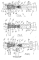
- the number 1 indicates a snap coupling apparatus that can be used for the activation or deactivation of devices being generally fluid-dynamic operated.
- the snap coupling apparatus comprises a stationary part 2 suitable for supplying the fluid and a mobile part 3 which uses said fluid for its functional operation.
- the mobile part 3 of the snap coupling apparatus 1 comprises a balancing shaft 3.
- the snap coupling apparatus 1 comprises a valve element 4, normally closed, which can be rigidly mounted on the mobile part 3 of the snap coupling apparatus 1, and a corresponding stationary distributor 5 for distributing the fluid which is mounted on the stationary part 2 of the snap coupling apparatus 1.
- the stationary distributor 5 can be coupled with the valve element 4 for the activation of the snap coupling apparatus 1 and be uncoupled from the valve element 4 for the deactivation of said snap coupling apparatus 1.
- the elastic means 8 are suitable for contrasting the motion of the closing element 7 into the valve element 4.
- the valve element 4 further comprises a pipe 9, passing through the bottom part 206 of the body 6 and suitable for connecting the latest with the fluid-dynamic operated device, a collar 10 internally protruding from the opening 106 in radial direction and suitable for stopping and limiting the closing element 7, and seal means 11 interposed between the closing element 7 and the collar 10 and suitable for assuring the sealing of the body 6 in its closed position, so as any fluid can not flow into the body 6.
- the stationary distributor 5 comprises a casing 12 for containing the stationary distributor 5, which is provided with three fluid inlets placed in order and preferably transversally, a first fluid inlet 112, a second fluid inlet 212, and a third fluid inlet 312.
- the casing 12 is also provided with a chamber 13, axially positioned into the casing 12, in which can axially slides a slider 14, the slider 14 is contrasted in its sliding movement by first elastic means 15 interposed between the chamber 13 and the slider 14.
- the stem element 17 can be axially moved forward and backward into the seat 18 so as to be moved toward the frontal opening 16 in the activation phase of the fluid-dynamic devices and respectively to be removed from the frontal opening 16 in the deactivation phase of the fluid-dynamic devices, as is described in greater detail below.
- the stem element 17 is contrasted in its movement by the second elastic means 19.
- the first elastic means 15 and the second elastic means 19 comprise a helical compression spring which is coiled respectively externally at the slider 14 and around the stem element 17.
- the inlet 20 can be put in correspondence with the first fluid inlet 112, and it can be also connected with the front opening 16 by means of a pipe section 120 obtained in the slider 14 externally to the stem element 17 and extending coaxially with the stem element 17.
- the first fluid inlet 112 and the second fluid inlet 212 are arranged for allowing the inlet of the fluid used to activate the fluid-dynamic devices and can be substantially simultaneously feed, whereas to the third fluid inlet 312, which can be feed alternatively to first fluid inlet 112 and to the second fluid 212, can be supplied the fluid to be used to deactivate the fluid-dynamic devices.
- seal means 21 On the perimeter of the front outlet 16 are provided further seal means 21 that can be placed in contact with the abutting and limiting collar 10 when the stationary distributor 5 is coupled with the valve element 4.
- Annular seal means 22 are provided between the chamber 13 and the slider 14 and also between the seat 18 and the stem element 17, these annular seal means 22 comprises, for example, a gasket made of elastic material, usually named as "O-ring".
- a snap coupling apparatus 1' comprises, as in the first embodiment, a stationary part 2, a valve element 4, normally closed, which can be rigidly mounted on a mobile part 3' of the snap coupling apparatus 1', and at least a stationary distributor 5' for distributing the fluids.
- the stationary distributor 5' can be coupled with or uncoupled from the valve element 4' for opening its supply link and activating said fluid-dynamic device.
- the valve element 4' comprises a body 6' that is essentially bell-shaped and provided with an opening 106' for allowing the inlet of the fluid into the valve element 4' and with a bottom part 206'.
- the opening 106' can be closed with at least a stem element 7' provided with an enlarged head 107'.
- a pipe 9' that orthogonally passes through the bottom part 206' so as to connect the valve element 4' with a fluid-dynamic device.
- a casing 12' is externally provided to the stationary distributor 5', the casing comprises at least two essentially fluid inlets placed in order preferably transversal, comprising a first fluid inlet 112' and a second fluid inlet 212'.
- the casing 12' is so configured as to seal the stationary distributor 5', and it is provided with a chamber 13', into which is mounted a slider 14 so arranged as to slide into the chamber 13'.
- the slider 14' is provided with a front outlet 16' for allowing the outlet of a fluid and a rod 17' for sealed coupling the slider 14' with the valve element 4', or more precisely, with its opening 106'.
- the slider 14' comprises a pipe section 18' coaxial with the slider 14', which is connected to the front outlet 16' and in which the fluid flows, and, peripherally, a peripheral transverse inlet 20', preferably in the shape of an external groove, which can alternatively be coupled with one of the two fluid inlets, particularly with the first fluid inlet 112', and which can be connected to the coaxial pipe section 18'.
- the front outlet 16' is perimetrically provided with further sealing elements 21', which are usually of the type known as "O-rings", and which can be placed in contact with the collar 10'.
- the elastic means 15' comprises at least a helical spring 19', which can be loaded by compression and which is interposed between the slider 14' and chamber 13' in which the slider 14' slides.
- the helical spring 19' can be replaced, for example, with a double-acting actuator connected to the slider 14' in a manner that is well-known persons skilled in the art.
- the snap coupling apparatus 1' comprises also a deactivation element 2' comprising a thrust element 22' that by contact thrusts the stem element 7' so as to re-insert the stem element 7' into the body 6', and an alternate motion actuator 23' having a reciprocating motion which is per se known and suitable for moving the thrust element 22'.
- the thrust element 22' is essentially transversal with respect to the stem element 7' and can comprise a wedge-shaped body 24' integrally mounted on the actuator 23' and so oriented as to have at least one oblique face turned toward the stem element 7' in order to maintain the sliding condition between the stem element 7' and the actuator 23'.
- the functioning of the snap coupling apparatus 1 is described below for both of the possible embodiments, and it is referred, by way of example only, to the possible use on a wheel-balancing machine. Reference will be in particular made to the activation or deactivation of the usually device used for locking the wheels on a balancing shaft 3 of a generic balancing machine.
- the balancing shaft 3 is provided with a rear protrusion 200 inside which is provided an axial channel 201 into which flows the pipe 9.
- valve element 4 is mounted on one end of the rear protrusion 200, whereas the stationary distributor 5 is integrally attached to the frame of a balancing machine, in a manner known to a person skilled in the art, so as the stationary distributor 5 faces and is coaxially aligned with, the valve element 4.
- the locking device When it is necessary to activate the locking device for locking a wheel on a balancing shaft of the balancing machine, the locking device being operated by compressed air, the compressed air is simultaneously supplied through the first fluid inlet 112 and through the second fluid inlet 212.
- the snap coupling apparatus 1 is in the configuration shown in the Figure 1, in which the slider 14 is so positioned into the casing 12, as the inlet 20 is uncoupled with the first fluid inlet 112, therefore, the compressed air flows into the second fluid inlet 212.
- the end portion of the slider 14 press onto the closing element 7 that, after have overcoming the resistance of the elastic means 8, moves toward the inside of the body 6 so opening the opening 106.
- the compressed air generates into the activated locking device and in the axial channel 201 a pressure acting on the closing element 7.
- the spring means 8 that are in the loaded configuration tends to extend, so exerting a force on the closing element 7 in the same direction of the pressure exerted by the compressed air.
- closing element 7 is made to return in its first position, so closing the opening 106 again.
- the balancing shaft of the balancing machine can be made to rotate, while the locking device is maintained in an active condition thus without being connected to the stationary distributor 5.
- the balancing shaft can be stopped.
- the stem element 17 slides until its end portion protrudes from the slider 14 and abuts against the closing element 7.
- the closing element 7 moves again backward into the body 6, thus reopening the opening 106, through which the compressed air escape from the axial channel 201 in which it was previously introduced.
- the escaping of the compressed air from the axial channel 201 causes the deactivation of the locking device, which can be therefore removed from the balancing shaft.
- the second embodiment essentially differs by the first one in regard to the deactivation phase, which is no longer performed by the stem element 17, but by the deactivation element 2' and in particular by the wedge-shaped element 24' thereof.
- the wedge-shaped element 24' acts on the stem element 7', going, under the action of the actuator 23', into contact with the stem element 7' and pushing it to return into the body 6' of the valve element 4'.
- the action of the deactivation element 2' is alternated with respect to that of the slider 14' of the stationary distributor 5'.
- the opening 106' is no longer regulated by a closing element 7, but by a stem element 7' having an enlarged head 107', which is provided, on the side toward the body 6 of the slider 14'.
- seal means 11' to adhere to the stem element 7' so as to seal the valve element 4' during the activated phase of the device.
Landscapes
- Engineering & Computer Science (AREA)
- General Engineering & Computer Science (AREA)
- Mechanical Engineering (AREA)
- Quick-Acting Or Multi-Walled Pipe Joints (AREA)
Applications Claiming Priority (2)
| Application Number | Priority Date | Filing Date | Title |
|---|---|---|---|
| ITMO20020207 | 2002-07-19 | ||
| IT2002MO000207A ITMO20020207A1 (it) | 2002-07-19 | 2002-07-19 | Attacco rapido per la attivazione e la disattivazione di dispositivi ad azionamento fluidodinamico |
Publications (4)
| Publication Number | Publication Date |
|---|---|
| EP1384934A2 true EP1384934A2 (de) | 2004-01-28 |
| EP1384934A3 EP1384934A3 (de) | 2004-09-22 |
| EP1384934B1 EP1384934B1 (de) | 2009-04-01 |
| EP1384934B8 EP1384934B8 (de) | 2009-08-19 |
Family
ID=11451120
Family Applications (1)
| Application Number | Title | Priority Date | Filing Date |
|---|---|---|---|
| EP03016358A Expired - Lifetime EP1384934B8 (de) | 2002-07-19 | 2003-07-18 | Schnappkupplung zum Aktivieren und Deaktivieren fluidbetriebener Geräte |
Country Status (4)
| Country | Link |
|---|---|
| US (1) | US7150291B2 (de) |
| EP (1) | EP1384934B8 (de) |
| DE (1) | DE60326909D1 (de) |
| IT (1) | ITMO20020207A1 (de) |
Families Citing this family (2)
| Publication number | Priority date | Publication date | Assignee | Title |
|---|---|---|---|---|
| US8453675B2 (en) * | 2009-12-01 | 2013-06-04 | Deublin Company | Rotary union with selectively controlled seal |
| ES2634675T3 (es) | 2015-05-20 | 2017-09-28 | Corghi S.P.A. | Máquina de equilibrado |
Family Cites Families (12)
| Publication number | Priority date | Publication date | Assignee | Title |
|---|---|---|---|---|
| US933290A (en) * | 1908-08-31 | 1909-09-07 | William J Clay | Reel-operated hydrant. |
| US2362339A (en) * | 1943-04-28 | 1944-11-07 | Euclid Road Machinery Co | Fluid operated servomotor |
| US3140102A (en) | 1962-11-23 | 1964-07-07 | Erwin H Gebhart | Releasable fluid line coupling |
| US3596567A (en) * | 1969-08-12 | 1971-08-03 | Milton L Benjamin | Fail-safe valve assembly for power chuck motors and the like |
| SE373506B (sv) * | 1973-05-29 | 1975-02-10 | Alfa Laval Ab | Anordning for att genom tryckfall overfora ett fluidum mellan en stillastaende och en roterande maskindel |
| DE3542014C1 (de) * | 1985-11-28 | 1987-01-02 | Glyco Antriebstechnik Gmbh | Druckbezogene schaltbare Drehdurchfuehrung |
| EP0365189B1 (de) | 1988-10-21 | 1995-06-14 | Kabushiki Kaisha Kosmek | Schnellkupplung |
| US4976282A (en) * | 1989-04-12 | 1990-12-11 | Deublin Company | Coolant union with fluid actuated seal assembly |
| DE4210009C2 (de) * | 1992-03-27 | 1994-05-11 | Heidelberger Druckmasch Ag | Drehdurchführung |
| US5462084A (en) | 1994-03-01 | 1995-10-31 | Kabushiki Kaisha Kosmek | Quick-acting coupling |
| DE19543612C1 (de) * | 1995-11-23 | 1997-05-07 | Glyco Antriebstechnik Gmbh | Spannvorrichtung mit integrierter Fluid-Drehdurchführung |
| US6386221B1 (en) * | 2001-04-05 | 2002-05-14 | Snap-Tite Technologies, Inc. | Journal mounted solenoid valve |
-
2002
- 2002-07-19 IT IT2002MO000207A patent/ITMO20020207A1/it unknown
-
2003
- 2003-07-18 EP EP03016358A patent/EP1384934B8/de not_active Expired - Lifetime
- 2003-07-18 US US10/622,670 patent/US7150291B2/en not_active Expired - Fee Related
- 2003-07-18 DE DE60326909T patent/DE60326909D1/de not_active Expired - Fee Related
Also Published As
| Publication number | Publication date |
|---|---|
| ITMO20020207A0 (it) | 2002-07-19 |
| DE60326909D1 (de) | 2009-05-14 |
| EP1384934A3 (de) | 2004-09-22 |
| EP1384934B1 (de) | 2009-04-01 |
| EP1384934B8 (de) | 2009-08-19 |
| US7150291B2 (en) | 2006-12-19 |
| ITMO20020207A1 (it) | 2004-01-19 |
| US20040016462A1 (en) | 2004-01-29 |
Similar Documents
| Publication | Publication Date | Title |
|---|---|---|
| EP0140432B1 (de) | Absperrventil | |
| KR100522754B1 (ko) | 안전밸브와 압력 해제 밸브를 가진 신속 결합 파이프 피팅 | |
| JP6385160B2 (ja) | 非常用機能を有する液圧式の作動装置に用いられる4チャンバ型シリンダおよび4チャンバ型シリンダを備えた液圧式の作動装置 | |
| US6805332B2 (en) | Inflatable seat valve | |
| CZ342096A3 (cs) | Hydraulicky ovládaný závěrný diferenciál s řadovým pístovým prostředkem | |
| JPH0854089A (ja) | 安全弁付パイプ迅速連結具 | |
| JPH03242470A (ja) | 液圧装置 | |
| JP5421464B2 (ja) | 空気注入装置、システム及びその利用方法 | |
| US5492148A (en) | Rinsing assembly with swivel actuating valve | |
| US7150291B2 (en) | Fluid attachment for the activation and deactivation of fluid driven dynamic devices | |
| US5462084A (en) | Quick-acting coupling | |
| CA2390370C (en) | Quick-action coupling of a flat design | |
| CA2164412A1 (en) | Height control valve and dump valve therefor | |
| US2479454A (en) | Fluid flow control apparatus | |
| JPS60260774A (ja) | 球弁 | |
| CA2484235C (en) | Connection coupling | |
| JP6209693B1 (ja) | 高圧水用流路切替え装置及び遠隔操作用水圧駆動ロボット | |
| JPS63297825A (ja) | アクチュエータ | |
| US5325763A (en) | Internal check valve | |
| US20100089716A1 (en) | Clutch | |
| EP4263243A1 (de) | Drehgelenk | |
| EP1143813B1 (de) | Verfahren und vorrichtung zur regulation der strömung eines pumpbaren nahrungsmittels | |
| US4987789A (en) | Swivel disk friction gearing | |
| US3778022A (en) | Valve | |
| JP6567916B2 (ja) | カップリング装置 |
Legal Events
| Date | Code | Title | Description |
|---|---|---|---|
| PUAI | Public reference made under article 153(3) epc to a published international application that has entered the european phase |
Free format text: ORIGINAL CODE: 0009012 |
|
| AK | Designated contracting states |
Kind code of ref document: A2 Designated state(s): AT BE BG CH CY CZ DE DK EE ES FI FR GB GR HU IE IT LI LU MC NL PT RO SE SI SK TR |
|
| AX | Request for extension of the european patent |
Extension state: AL LT LV MK |
|
| PUAL | Search report despatched |
Free format text: ORIGINAL CODE: 0009013 |
|
| AK | Designated contracting states |
Kind code of ref document: A3 Designated state(s): AT BE BG CH CY CZ DE DK EE ES FI FR GB GR HU IE IT LI LU MC NL PT RO SE SI SK TR |
|
| AX | Request for extension of the european patent |
Extension state: AL LT LV MK |
|
| 17P | Request for examination filed |
Effective date: 20050314 |
|
| AKX | Designation fees paid |
Designated state(s): DE IT |
|
| 17Q | First examination report despatched |
Effective date: 20061013 |
|
| GRAP | Despatch of communication of intention to grant a patent |
Free format text: ORIGINAL CODE: EPIDOSNIGR1 |
|
| GRAS | Grant fee paid |
Free format text: ORIGINAL CODE: EPIDOSNIGR3 |
|
| GRAA | (expected) grant |
Free format text: ORIGINAL CODE: 0009210 |
|
| AK | Designated contracting states |
Kind code of ref document: B1 Designated state(s): DE IT |
|
| REF | Corresponds to: |
Ref document number: 60326909 Country of ref document: DE Date of ref document: 20090514 Kind code of ref document: P |
|
| PGFP | Annual fee paid to national office [announced via postgrant information from national office to epo] |
Ref country code: DE Payment date: 20090825 Year of fee payment: 7 |
|
| PLBE | No opposition filed within time limit |
Free format text: ORIGINAL CODE: 0009261 |
|
| STAA | Information on the status of an ep patent application or granted ep patent |
Free format text: STATUS: NO OPPOSITION FILED WITHIN TIME LIMIT |
|
| 26N | No opposition filed |
Effective date: 20100105 |
|
| PGFP | Annual fee paid to national office [announced via postgrant information from national office to epo] |
Ref country code: IT Payment date: 20090728 Year of fee payment: 7 |
|
| PG25 | Lapsed in a contracting state [announced via postgrant information from national office to epo] |
Ref country code: DE Free format text: LAPSE BECAUSE OF NON-PAYMENT OF DUE FEES Effective date: 20110201 |
|
| REG | Reference to a national code |
Ref country code: DE Ref legal event code: R119 Ref document number: 60326909 Country of ref document: DE Effective date: 20110201 |
|
| PG25 | Lapsed in a contracting state [announced via postgrant information from national office to epo] |
Ref country code: IT Free format text: LAPSE BECAUSE OF NON-PAYMENT OF DUE FEES Effective date: 20100718 |