EP1382816A2 - Anordnung zumindest zweier Abgasturbolader - Google Patents
Anordnung zumindest zweier Abgasturbolader Download PDFInfo
- Publication number
- EP1382816A2 EP1382816A2 EP03010081A EP03010081A EP1382816A2 EP 1382816 A2 EP1382816 A2 EP 1382816A2 EP 03010081 A EP03010081 A EP 03010081A EP 03010081 A EP03010081 A EP 03010081A EP 1382816 A2 EP1382816 A2 EP 1382816A2
- Authority
- EP
- European Patent Office
- Prior art keywords
- exhaust gas
- turbine
- housings
- arrangement according
- cylinders
- Prior art date
- Legal status (The legal status is an assumption and is not a legal conclusion. Google has not performed a legal analysis and makes no representation as to the accuracy of the status listed.)
- Granted
Links
Images

Classifications
-
- F—MECHANICAL ENGINEERING; LIGHTING; HEATING; WEAPONS; BLASTING
- F01—MACHINES OR ENGINES IN GENERAL; ENGINE PLANTS IN GENERAL; STEAM ENGINES
- F01D—NON-POSITIVE DISPLACEMENT MACHINES OR ENGINES, e.g. STEAM TURBINES
- F01D25/00—Component parts, details, or accessories, not provided for in, or of interest apart from, other groups
- F01D25/24—Casings; Casing parts, e.g. diaphragms, casing fastenings
-
- F—MECHANICAL ENGINEERING; LIGHTING; HEATING; WEAPONS; BLASTING
- F02—COMBUSTION ENGINES; HOT-GAS OR COMBUSTION-PRODUCT ENGINE PLANTS
- F02B—INTERNAL-COMBUSTION PISTON ENGINES; COMBUSTION ENGINES IN GENERAL
- F02B37/00—Engines characterised by provision of pumps driven at least for part of the time by exhaust
- F02B37/007—Engines characterised by provision of pumps driven at least for part of the time by exhaust with exhaust-driven pumps arranged in parallel, e.g. at least one pump supplying alternatively
-
- F—MECHANICAL ENGINEERING; LIGHTING; HEATING; WEAPONS; BLASTING
- F02—COMBUSTION ENGINES; HOT-GAS OR COMBUSTION-PRODUCT ENGINE PLANTS
- F02B—INTERNAL-COMBUSTION PISTON ENGINES; COMBUSTION ENGINES IN GENERAL
- F02B37/00—Engines characterised by provision of pumps driven at least for part of the time by exhaust
- F02B37/12—Control of the pumps
- F02B37/18—Control of the pumps by bypassing exhaust from the inlet to the outlet of turbine or to the atmosphere
-
- F—MECHANICAL ENGINEERING; LIGHTING; HEATING; WEAPONS; BLASTING
- F01—MACHINES OR ENGINES IN GENERAL; ENGINE PLANTS IN GENERAL; STEAM ENGINES
- F01N—GAS-FLOW SILENCERS OR EXHAUST APPARATUS FOR MACHINES OR ENGINES IN GENERAL; GAS-FLOW SILENCERS OR EXHAUST APPARATUS FOR INTERNAL-COMBUSTION ENGINES
- F01N13/00—Exhaust or silencing apparatus characterised by constructional features
- F01N13/08—Other arrangements or adaptations of exhaust conduits
- F01N13/10—Other arrangements or adaptations of exhaust conduits of exhaust manifolds
- F01N13/107—More than one exhaust manifold or exhaust collector
-
- F—MECHANICAL ENGINEERING; LIGHTING; HEATING; WEAPONS; BLASTING
- F05—INDEXING SCHEMES RELATING TO ENGINES OR PUMPS IN VARIOUS SUBCLASSES OF CLASSES F01-F04
- F05D—INDEXING SCHEME FOR ASPECTS RELATING TO NON-POSITIVE-DISPLACEMENT MACHINES OR ENGINES, GAS-TURBINES OR JET-PROPULSION PLANTS
- F05D2220/00—Application
- F05D2220/40—Application in turbochargers
-
- Y—GENERAL TAGGING OF NEW TECHNOLOGICAL DEVELOPMENTS; GENERAL TAGGING OF CROSS-SECTIONAL TECHNOLOGIES SPANNING OVER SEVERAL SECTIONS OF THE IPC; TECHNICAL SUBJECTS COVERED BY FORMER USPC CROSS-REFERENCE ART COLLECTIONS [XRACs] AND DIGESTS
- Y02—TECHNOLOGIES OR APPLICATIONS FOR MITIGATION OR ADAPTATION AGAINST CLIMATE CHANGE
- Y02T—CLIMATE CHANGE MITIGATION TECHNOLOGIES RELATED TO TRANSPORTATION
- Y02T10/00—Road transport of goods or passengers
- Y02T10/10—Internal combustion engine [ICE] based vehicles
- Y02T10/12—Improving ICE efficiencies
Definitions
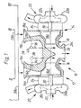
- a drive shaft 30 can be rotated in the bearing housing 24 mounted on the one hand, which protrudes into the turbine housing 16a, 18a Exhaust turbines 16d, 18d and those in the compressor housing 20a, 22a protruding compressor impellers 20c, 22c. As can be seen, the drive shafts 30 are in alignment (common Center axis of rotation 32).
- the compressor side inputs and Outflow channels in the compressor housings 20a, 22a are known Executed in a manner and therefore not shown in detail.
Landscapes
- Engineering & Computer Science (AREA)
- Mechanical Engineering (AREA)
- General Engineering & Computer Science (AREA)
- Chemical & Material Sciences (AREA)
- Combustion & Propulsion (AREA)
- Supercharger (AREA)
Abstract
Description
Die Bypassleitungen 34, 36 sowie ggf. die Bypassventile 38, 40 können unmittelbar als Kanäle in die Turbinengehäuse 16a, 18a integriert sein.
Claims (9)
- Anordnung zumindest zweier Abgasturbolader an einer Brennkraftmaschine mit mehreren Zylindern, insbesondere in einem Kraftfahrzeug, bei der die zwei Turbinengehäuse an das Abgassystem der Brennkraftmaschine angeschlossen und einander unmittelbar benachbart sind und die jeweils eine Turbine mittels einer Antriebswelle mit je einem Verdichter verbunden ist, wobei die Antriebswellen in entsprechenden Lagergehäusen drehbar gelagert sind, dadurch gekennzeichnet, dass die Turbinengehäuse (16a, 18a) derart ausgerichtet sind, dass die Antriebswellen (30) zumindest im wesentlichen in einer Flucht (32) zueinander liegen und dass die Lagergehäuse (24) beiderseits an die Turbinengehäuse (16a, 18a) anschließen.
- Anordnung nach Anspruch 1, dadurch gekennzeichnet, dass die Turbinengehäuse (16a, 18a) zu einer Baueinheit zusammengegossen sind.
- Anordnung nach Anspruch 1 oder 2, dadurch gekennzeichnet, dass die Einströmkanäle (16b, 18b) der Turbinengehäuse (16a, 18a) über voneinander getrennte Abgasleitungen (28a, 28b) mit bestimmten Zylindern der Brennkraftmaschine verbunden sind.
- Anordnung nach Anspruch 3, dadurch gekennzeichnet, dass bei einer Vierzylinder-Reihen-Brennkraftmaschine der eine Einströmkanal (16b) mit zwei Zylindern (I und IV) und der andere Einströmkanal (18b) mit den anderen zwei Zylindern (II und III) verbunden ist, wobei der Zündabstand zwischen den jeweils abgasseitig zusammengeschalteten Zylindern jeweils 360 Grad (Kurbelwelle) beträgt.
- Anordnung nach einem oder mehreren der Ansprüche 1 bis 4, dadurch gekennzeichnet, dass die Turbinengehäuse (16a, 18a) einen einheitlichen Abströmkanal (26) für das Abgas zu einer stromab liegenden Abgasleitung aufweisen.
- Anordnung nach einem oder mehreren der Ansprüche 1 bis 5, dadurch gekennzeichnet, dass beide Abgasturbolader (12, 14) mit je einer getrennt voneinander ausgeführten Bypassleitung (34, 36) versehen sind, die über je ein Bypassventil (38, 40) gesteuert voneinander getrennte Ladedruckregelungen ermöglichen.
- Anordnung nach einem oder mehreren der Ansprüche 1 bis 5, dadurch gekennzeichnet, dass beide Abgasturbolader (12, 14) mit je einer Bypassleitung (56c, 58c) versehen sind, die im Bereich eines einzigen Bypassventiles (60) zusammengeführt eine einheitliche Ladedruckregelung ermöglichen.
- Anordnung nach Anspruch 6 oder 7, dadurch gekennzeichnet, dass die Bypassleitungen (56c, 58c) in die Turbinengehäuse (56a, 58a) integriert sind.
- Anordnung nach einem oder mehreren der Ansprüche 6 bis 8, dadurch gekennzeichnet, dass die in die Turbinengehäuse (56a, 58a) integrierten Bypassleitungen (56c, 58c) von den Einströmkanälen (56b, 58b) abzweigen und etwa mittig zwischen den beiden Turbinengehäusen (56a, 58a) zusammengeführt sind und dass das Bypassventil (60) mit seiner Ventilöffnung (62) in den Abströmkanal (26) stromab der Abgasturbinen (16c, 18c) mündet.
Applications Claiming Priority (2)
| Application Number | Priority Date | Filing Date | Title |
|---|---|---|---|
| DE10232738A DE10232738B4 (de) | 2002-07-19 | 2002-07-19 | Anordnung zumindest zweier Abgasturbolader |
| DE10232738 | 2002-07-19 |
Publications (3)
| Publication Number | Publication Date |
|---|---|
| EP1382816A2 true EP1382816A2 (de) | 2004-01-21 |
| EP1382816A3 EP1382816A3 (de) | 2005-08-10 |
| EP1382816B1 EP1382816B1 (de) | 2009-08-05 |
Family
ID=29762056
Family Applications (1)
| Application Number | Title | Priority Date | Filing Date |
|---|---|---|---|
| EP03010081A Expired - Lifetime EP1382816B1 (de) | 2002-07-19 | 2003-05-03 | Anordnung zumindest zweier Abgasturbolader |
Country Status (4)
| Country | Link |
|---|---|
| US (1) | US6766645B2 (de) |
| EP (1) | EP1382816B1 (de) |
| DE (2) | DE10232738B4 (de) |
| ES (1) | ES2328913T3 (de) |
Cited By (5)
| Publication number | Priority date | Publication date | Assignee | Title |
|---|---|---|---|---|
| EP1878893A1 (de) * | 2006-07-13 | 2008-01-16 | Bayerische Motoren Werke Aktiengesellschaft | Abgasturboladeranordnung |
| US7966816B1 (en) | 2010-01-11 | 2011-06-28 | Ford Global Technologies | Turbocharged internal combustion engine |
| US20120260889A1 (en) * | 2009-11-06 | 2012-10-18 | Rolf Gunkel | Suction housing |
| US8490395B2 (en) | 2004-12-14 | 2013-07-23 | Borgwarner Inc. | Turbine regulating valve system |
| CN105257348A (zh) * | 2015-10-29 | 2016-01-20 | 无锡康明斯涡轮增压技术有限公司 | 双流道涡轮增压器的压力对称旁通装置 |
Families Citing this family (12)
| Publication number | Priority date | Publication date | Assignee | Title |
|---|---|---|---|---|
| US7310947B2 (en) * | 2002-07-26 | 2007-12-25 | Mtu Friedrichshafen Gmbh | Internal combustion engine with waste gas turbo-chargers |
| DE102006024783A1 (de) * | 2006-05-27 | 2007-11-29 | Bayerische Motoren Werke Ag | Zweistufige Abgasturboladeranordnung |
| US8206133B2 (en) * | 2008-08-12 | 2012-06-26 | GM Global Technology Operations LLC | Turbocharger housing with integral inlet and outlet openings |
| US20120159947A1 (en) * | 2009-02-19 | 2012-06-28 | Volvo Lastvagnar Ab | Method and apparatus for controlling turbine efficiency |
| JP5879685B2 (ja) * | 2010-12-28 | 2016-03-08 | いすゞ自動車株式会社 | 多段過給装置 |
| EP2522843B1 (de) * | 2011-05-12 | 2014-09-03 | Ford Global Technologies, LLC | Aufgeladene Brennkraftmaschine mit separaten Abgaskrümmern und Verfahren zum Betreiben einer derartigen Brennkraftmaschine |
| US9074521B2 (en) * | 2012-03-21 | 2015-07-07 | Ford Global Technologies, Llc | Turbocharger system having a shared bypass conduit and wastegate |
| US9133759B2 (en) | 2012-06-27 | 2015-09-15 | Cummins Inc. | Systems, devices and methods for providing airflow to an air compressor |
| US9157363B2 (en) | 2012-08-21 | 2015-10-13 | Ford Global Technologies, Llc | Twin independent boosted I4 engine |
| CN105705745B (zh) * | 2013-11-07 | 2018-07-20 | 本田技研工业株式会社 | 排气结构 |
| US9528518B2 (en) | 2014-06-16 | 2016-12-27 | Cummins Inc. | System, apparatus and methods for diverting airflow to a pressure source |
| DE102016010640A1 (de) | 2016-09-02 | 2018-03-08 | Daimler Ag | Aufladeeinrichtung für eine Verbrennungskraftmaschine, sowie Verbrennungskraftmaschine mit einer solchen Aufladeeinrichtung |
Citations (2)
| Publication number | Priority date | Publication date | Assignee | Title |
|---|---|---|---|---|
| DE19822874A1 (de) | 1998-05-22 | 1999-11-25 | Man Nutzfahrzeuge Ag | Aufladesystem für Brennkraftmaschinen |
| DE19948220A1 (de) | 1999-10-06 | 2001-01-25 | Daimler Chrysler Ag | Brennkraftmaschine mit zwei Abgasturboladern |
Family Cites Families (19)
| Publication number | Priority date | Publication date | Assignee | Title |
|---|---|---|---|---|
| US1310682A (en) * | 1918-05-14 | 1919-07-22 | Earl H Sherbondy | Duplex turbo-compressor. |
| FR645393A (fr) * | 1927-01-20 | 1928-10-24 | Escher Wyss & Cie Const Mec | Pompe centrifuge |
| US2359615A (en) * | 1941-04-09 | 1944-10-03 | Wright Aeronautical Corp | Multisupercharger control system |
| US3027706A (en) * | 1961-03-24 | 1962-04-03 | Caterpillar Tractor Co | Turbocharged v-type engine |
| GB1102085A (en) * | 1966-03-11 | 1968-02-07 | Armstrong W G Whitworth & Co | Improved turbocharged internal combustion engine |
| DE3108288C2 (de) * | 1981-03-05 | 1986-01-16 | M.A.N. Maschinenfabrik Augsburg-Nürnberg AG, 8900 Augsburg | Aufgeladene Brennkraftmaschine |
| JPS59160027A (ja) * | 1983-03-02 | 1984-09-10 | Mazda Motor Corp | 多気筒4サイクルエンジンのターボ過給装置 |
| JPS60116821A (ja) * | 1983-11-29 | 1985-06-24 | Hino Motors Ltd | 排気タ−ビン過給機 |
| DE3629841A1 (de) * | 1986-09-02 | 1987-05-21 | Daimler Benz Ag | Mehrzylindrige aufgeladene brennkraftmaschine |
| DE3735736A1 (de) * | 1987-10-22 | 1989-05-03 | Porsche Ag | Vorrichtung zum steuern einer turboladeranlage |
| JP2845448B2 (ja) * | 1988-06-06 | 1999-01-13 | マツダ株式会社 | ターボ過給機付エンジンの排気センサ取付構造 |
| JPH02119627A (ja) * | 1988-10-29 | 1990-05-07 | Mazda Motor Corp | 過給機付エンジンの吸気装置 |
| DE3838149A1 (de) * | 1988-11-10 | 1990-05-17 | Daimler Benz Ag | Aufladesystem fuer eine brennkraftmaschine |
| DE3908286C1 (de) * | 1989-03-14 | 1990-02-22 | Daimler-Benz Aktiengesellschaft, 7000 Stuttgart, De | |
| JPH0370818A (ja) * | 1989-08-08 | 1991-03-26 | Mazda Motor Corp | 過給機付エンジンの排気装置 |
| JP3306845B2 (ja) * | 1996-06-10 | 2002-07-24 | ヤンマーディーゼル株式会社 | 内燃機関の排気系構造 |
| DE19809854A1 (de) * | 1998-02-06 | 1999-08-12 | Skl Motoren Systemtech | Abgasabführung |
| DE19832020C1 (de) * | 1998-07-16 | 1999-04-01 | Bosch Gmbh Robert | Verfahren und Vorrichtung zum Überwachen der Funktion zweier Abgasturbolader |
| DE19849495C2 (de) * | 1998-10-27 | 2001-01-25 | Daimler Chrysler Ag | Aufgeladene Brennkraftmaschine mit einer die Abgasturbine überbrückenden Umgehungsleitung |
-
2002
- 2002-07-19 DE DE10232738A patent/DE10232738B4/de not_active Expired - Fee Related
-
2003
- 2003-05-03 DE DE50311771T patent/DE50311771D1/de not_active Expired - Lifetime
- 2003-05-03 ES ES03010081T patent/ES2328913T3/es not_active Expired - Lifetime
- 2003-05-03 EP EP03010081A patent/EP1382816B1/de not_active Expired - Lifetime
- 2003-07-14 US US10/617,748 patent/US6766645B2/en not_active Expired - Fee Related
Patent Citations (2)
| Publication number | Priority date | Publication date | Assignee | Title |
|---|---|---|---|---|
| DE19822874A1 (de) | 1998-05-22 | 1999-11-25 | Man Nutzfahrzeuge Ag | Aufladesystem für Brennkraftmaschinen |
| DE19948220A1 (de) | 1999-10-06 | 2001-01-25 | Daimler Chrysler Ag | Brennkraftmaschine mit zwei Abgasturboladern |
Cited By (6)
| Publication number | Priority date | Publication date | Assignee | Title |
|---|---|---|---|---|
| US8490395B2 (en) | 2004-12-14 | 2013-07-23 | Borgwarner Inc. | Turbine regulating valve system |
| EP1878893A1 (de) * | 2006-07-13 | 2008-01-16 | Bayerische Motoren Werke Aktiengesellschaft | Abgasturboladeranordnung |
| US20120260889A1 (en) * | 2009-11-06 | 2012-10-18 | Rolf Gunkel | Suction housing |
| US9404508B2 (en) * | 2009-11-06 | 2016-08-02 | Mtu Friedrichshafen Gmbh | Suction housing |
| US7966816B1 (en) | 2010-01-11 | 2011-06-28 | Ford Global Technologies | Turbocharged internal combustion engine |
| CN105257348A (zh) * | 2015-10-29 | 2016-01-20 | 无锡康明斯涡轮增压技术有限公司 | 双流道涡轮增压器的压力对称旁通装置 |
Also Published As
| Publication number | Publication date |
|---|---|
| DE10232738B4 (de) | 2005-04-21 |
| DE50311771D1 (de) | 2009-09-17 |
| US6766645B2 (en) | 2004-07-27 |
| DE10232738A1 (de) | 2004-02-05 |
| US20040011037A1 (en) | 2004-01-22 |
| EP1382816B1 (de) | 2009-08-05 |
| EP1382816A3 (de) | 2005-08-10 |
| ES2328913T3 (es) | 2009-11-19 |
Similar Documents
| Publication | Publication Date | Title |
|---|---|---|
| EP1382816B1 (de) | Anordnung zumindest zweier Abgasturbolader | |
| EP1394380B1 (de) | Aufladesystem für eine Brennkraftmaschine | |
| EP1274928B1 (de) | Turbolader-einrichtung für eine brennkraftmaschine | |
| EP1400667B1 (de) | Brennkraftmaschine mit Abgasturboaufladung | |
| DE102004055571A1 (de) | Abgasturbolader für eine Brennkraftmaschine | |
| DE10229116A1 (de) | Verbrennungsmotor und Verfahren zum Betreiben eines solchen | |
| DE102008044382A1 (de) | Motor mit sequentieller geteilter Reihenturboaufladung | |
| EP1275832A2 (de) | Vorrichtung zur mehrstufigen Aufladung einer Brennkraftmaschine | |
| WO2013020632A1 (de) | Verbrennungskraftmaschine für einen kraftwagen | |
| DE102008020745A1 (de) | Abgasstromführungseinrichtung und Brennkraftmaschine mit einer Abgasstromführungseinrichtung | |
| AT500458B1 (de) | Brennkraftmaschine, insbesondere otto-brennkraftmaschine | |
| WO2017102041A1 (de) | Ventilelement für eine turbine eines abgasturboladers | |
| DE102006031702A1 (de) | Brennkraftmaschine mit einem mehrflutigen Abgasturbolader | |
| DE102005053977B4 (de) | Brennkraftmaschine und Verfahren zum Betreiben einer Brennkraftmaschine | |
| DE19811782A1 (de) | Brennkraftmaschine mit zwei Abgasturboladern | |
| EP4405574B1 (de) | Verbrennungskraftmaschine für ein kraftfahrzeug, insbesondere für einen kraftwagen | |
| DE102017009452B4 (de) | Verbrennungskraftmaschine für ein Kraftfahrzeug und Kraftfahrzeug mit einer solchen Verbrennungskraftmaschine | |
| DE102018005460B3 (de) | Verbrennungskraftmaschine für ein Kraftfahrzeug, insbesondere für einen Kraftwagen, Verfahren zum Betreiben einer solchen Verbrennungskraftmaschine sowie Kraftfahrzeug mit einer solchen Verbrennungskraftmaschine | |
| DE102022000150B4 (de) | Turbine für einen Abgasturbolader, insbesondere eines Kraftfahrzeugs, sowie Verbrennungskraftmaschine | |
| EP0231824B1 (de) | Mehrzylinder-Brennkraftmaschine mit Abgasturbolader | |
| DE102019202380A1 (de) | Brennkraftmaschine mit einem Abgaskrümmer und einem Abgasturbolader | |
| DE102013216608B4 (de) | Abgasturboaufgeladene Brennkraftmaschine umfassend einen Verdichter mit zwei Laufrädern | |
| DE102018006413A1 (de) | Verbrennungskraftmaschine für einen Kraftwagen mit einem Abgaskrümmer und mit einem Abgasrückführventil | |
| DE102007011723A1 (de) | Brennkraftmaschine | |
| DE102006047322A1 (de) | Verbrennungsmotor mit Abgasturboladeranordnung |
Legal Events
| Date | Code | Title | Description |
|---|---|---|---|
| PUAI | Public reference made under article 153(3) epc to a published international application that has entered the european phase |
Free format text: ORIGINAL CODE: 0009012 |
|
| AK | Designated contracting states |
Kind code of ref document: A2 Designated state(s): AT BE BG CH CY CZ DE DK EE ES FI FR GB GR HU IE IT LI LU MC NL PT RO SE SI SK TR |
|
| AX | Request for extension of the european patent |
Extension state: AL LT LV MK |
|
| PUAL | Search report despatched |
Free format text: ORIGINAL CODE: 0009013 |
|
| RIC1 | Information provided on ipc code assigned before grant |
Ipc: 7F 01D 25/30 B Ipc: 7F 02C 6/12 B Ipc: 7F 02B 67/10 A Ipc: 7F 02B 37/18 B Ipc: 7F 02B 37/007 B |
|
| AK | Designated contracting states |
Kind code of ref document: A3 Designated state(s): AT BE BG CH CY CZ DE DK EE ES FI FR GB GR HU IE IT LI LU MC NL PT RO SE SI SK TR |
|
| AX | Request for extension of the european patent |
Extension state: AL LT LV MK |
|
| 17P | Request for examination filed |
Effective date: 20060210 |
|
| AKX | Designation fees paid |
Designated state(s): CZ DE ES FR GB IT |
|
| GRAP | Despatch of communication of intention to grant a patent |
Free format text: ORIGINAL CODE: EPIDOSNIGR1 |
|
| GRAS | Grant fee paid |
Free format text: ORIGINAL CODE: EPIDOSNIGR3 |
|
| GRAA | (expected) grant |
Free format text: ORIGINAL CODE: 0009210 |
|
| AK | Designated contracting states |
Kind code of ref document: B1 Designated state(s): CZ DE ES FR GB IT |
|
| REG | Reference to a national code |
Ref country code: GB Ref legal event code: FG4D Free format text: NOT ENGLISH |
|
| REF | Corresponds to: |
Ref document number: 50311771 Country of ref document: DE Date of ref document: 20090917 Kind code of ref document: P |
|
| REG | Reference to a national code |
Ref country code: ES Ref legal event code: FG2A Ref document number: 2328913 Country of ref document: ES Kind code of ref document: T3 |
|
| PLBE | No opposition filed within time limit |
Free format text: ORIGINAL CODE: 0009261 |
|
| STAA | Information on the status of an ep patent application or granted ep patent |
Free format text: STATUS: NO OPPOSITION FILED WITHIN TIME LIMIT |
|
| 26N | No opposition filed |
Effective date: 20100507 |
|
| PGFP | Annual fee paid to national office [announced via postgrant information from national office to epo] |
Ref country code: DE Payment date: 20140531 Year of fee payment: 12 |
|
| REG | Reference to a national code |
Ref country code: FR Ref legal event code: PLFP Year of fee payment: 13 |
|
| REG | Reference to a national code |
Ref country code: DE Ref legal event code: R231 Ref document number: 50311771 Country of ref document: DE |
|
| PG25 | Lapsed in a contracting state [announced via postgrant information from national office to epo] |
Ref country code: DE Free format text: LAPSE BECAUSE OF THE APPLICANT RENOUNCES Effective date: 20150522 |
|
| PGFP | Annual fee paid to national office [announced via postgrant information from national office to epo] |
Ref country code: GB Payment date: 20150518 Year of fee payment: 13 Ref country code: CZ Payment date: 20150430 Year of fee payment: 13 Ref country code: ES Payment date: 20150511 Year of fee payment: 13 |
|
| PGFP | Annual fee paid to national office [announced via postgrant information from national office to epo] |
Ref country code: IT Payment date: 20150527 Year of fee payment: 13 Ref country code: FR Payment date: 20150518 Year of fee payment: 13 |
|
| GBPC | Gb: european patent ceased through non-payment of renewal fee |
Effective date: 20160503 |
|
| PG25 | Lapsed in a contracting state [announced via postgrant information from national office to epo] |
Ref country code: CZ Free format text: LAPSE BECAUSE OF NON-PAYMENT OF DUE FEES Effective date: 20160503 |
|
| PG25 | Lapsed in a contracting state [announced via postgrant information from national office to epo] |
Ref country code: IT Free format text: LAPSE BECAUSE OF NON-PAYMENT OF DUE FEES Effective date: 20160503 |
|
| REG | Reference to a national code |
Ref country code: FR Ref legal event code: ST Effective date: 20170131 |
|
| PG25 | Lapsed in a contracting state [announced via postgrant information from national office to epo] |
Ref country code: FR Free format text: LAPSE BECAUSE OF NON-PAYMENT OF DUE FEES Effective date: 20160531 |
|
| PG25 | Lapsed in a contracting state [announced via postgrant information from national office to epo] |
Ref country code: GB Free format text: LAPSE BECAUSE OF NON-PAYMENT OF DUE FEES Effective date: 20160503 |
|
| PG25 | Lapsed in a contracting state [announced via postgrant information from national office to epo] |
Ref country code: ES Free format text: LAPSE BECAUSE OF NON-PAYMENT OF DUE FEES Effective date: 20160504 |
|
| REG | Reference to a national code |
Ref country code: ES Ref legal event code: FD2A Effective date: 20180626 |
|
| P01 | Opt-out of the competence of the unified patent court (upc) registered |
Effective date: 20230529 |