EP1380718A1 - Device for automatically actuating a sliding door of a vehicle - Google Patents
Device for automatically actuating a sliding door of a vehicle Download PDFInfo
- Publication number
- EP1380718A1 EP1380718A1 EP03014620A EP03014620A EP1380718A1 EP 1380718 A1 EP1380718 A1 EP 1380718A1 EP 03014620 A EP03014620 A EP 03014620A EP 03014620 A EP03014620 A EP 03014620A EP 1380718 A1 EP1380718 A1 EP 1380718A1
- Authority
- EP
- European Patent Office
- Prior art keywords
- sliding door
- chassis
- counter
- drive unit
- counter element
- Prior art date
- Legal status (The legal status is an assumption and is not a legal conclusion. Google has not performed a legal analysis and makes no representation as to the accuracy of the status listed.)
- Granted
Links
Images


Classifications
-
- E—FIXED CONSTRUCTIONS
- E05—LOCKS; KEYS; WINDOW OR DOOR FITTINGS; SAFES
- E05D—HINGES OR SUSPENSION DEVICES FOR DOORS, WINDOWS OR WINGS
- E05D15/00—Suspension arrangements for wings
- E05D15/06—Suspension arrangements for wings for wings sliding horizontally more or less in their own plane
- E05D15/10—Suspension arrangements for wings for wings sliding horizontally more or less in their own plane movable out of one plane into a second parallel plane
- E05D15/1042—Suspension arrangements for wings for wings sliding horizontally more or less in their own plane movable out of one plane into a second parallel plane with transversely moving carriage
- E05D15/1047—Suspension arrangements for wings for wings sliding horizontally more or less in their own plane movable out of one plane into a second parallel plane with transversely moving carriage specially adapted for vehicles
-
- B—PERFORMING OPERATIONS; TRANSPORTING
- B60—VEHICLES IN GENERAL
- B60J—WINDOWS, WINDSCREENS, NON-FIXED ROOFS, DOORS, OR SIMILAR DEVICES FOR VEHICLES; REMOVABLE EXTERNAL PROTECTIVE COVERINGS SPECIALLY ADAPTED FOR VEHICLES
- B60J5/00—Doors
- B60J5/04—Doors arranged at the vehicle sides
- B60J5/06—Doors arranged at the vehicle sides slidable; foldable
-
- E—FIXED CONSTRUCTIONS
- E05—LOCKS; KEYS; WINDOW OR DOOR FITTINGS; SAFES
- E05F—DEVICES FOR MOVING WINGS INTO OPEN OR CLOSED POSITION; CHECKS FOR WINGS; WING FITTINGS NOT OTHERWISE PROVIDED FOR, CONCERNED WITH THE FUNCTIONING OF THE WING
- E05F15/00—Power-operated mechanisms for wings
- E05F15/60—Power-operated mechanisms for wings using electrical actuators
- E05F15/603—Power-operated mechanisms for wings using electrical actuators using rotary electromotors
- E05F15/632—Power-operated mechanisms for wings using electrical actuators using rotary electromotors for horizontally-sliding wings
- E05F15/643—Power-operated mechanisms for wings using electrical actuators using rotary electromotors for horizontally-sliding wings operated by flexible elongated pulling elements, e.g. belts, chains or cables
- E05F15/646—Power-operated mechanisms for wings using electrical actuators using rotary electromotors for horizontally-sliding wings operated by flexible elongated pulling elements, e.g. belts, chains or cables allowing or involving a secondary movement of the wing, e.g. rotational or transversal
-
- E—FIXED CONSTRUCTIONS
- E05—LOCKS; KEYS; WINDOW OR DOOR FITTINGS; SAFES
- E05D—HINGES OR SUSPENSION DEVICES FOR DOORS, WINDOWS OR WINGS
- E05D15/00—Suspension arrangements for wings
- E05D15/06—Suspension arrangements for wings for wings sliding horizontally more or less in their own plane
- E05D15/10—Suspension arrangements for wings for wings sliding horizontally more or less in their own plane movable out of one plane into a second parallel plane
- E05D15/1042—Suspension arrangements for wings for wings sliding horizontally more or less in their own plane movable out of one plane into a second parallel plane with transversely moving carriage
- E05D2015/1055—Suspension arrangements for wings for wings sliding horizontally more or less in their own plane movable out of one plane into a second parallel plane with transversely moving carriage with slanted or curved track sections or cams
- E05D2015/1057—Suspension arrangements for wings for wings sliding horizontally more or less in their own plane movable out of one plane into a second parallel plane with transversely moving carriage with slanted or curved track sections or cams the carriage swinging or rotating in those track sections
-
- E—FIXED CONSTRUCTIONS
- E05—LOCKS; KEYS; WINDOW OR DOOR FITTINGS; SAFES
- E05Y—INDEXING SCHEME RELATING TO HINGES OR OTHER SUSPENSION DEVICES FOR DOORS, WINDOWS OR WINGS AND DEVICES FOR MOVING WINGS INTO OPEN OR CLOSED POSITION, CHECKS FOR WINGS AND WING FITTINGS NOT OTHERWISE PROVIDED FOR, CONCERNED WITH THE FUNCTIONING OF THE WING
- E05Y2201/00—Constructional elements; Accessories therefore
- E05Y2201/40—Motors; Magnets; Springs; Weights; Accessories therefore
- E05Y2201/43—Motors
- E05Y2201/434—Electromotors; Details thereof
-
- E—FIXED CONSTRUCTIONS
- E05—LOCKS; KEYS; WINDOW OR DOOR FITTINGS; SAFES
- E05Y—INDEXING SCHEME RELATING TO HINGES OR OTHER SUSPENSION DEVICES FOR DOORS, WINDOWS OR WINGS AND DEVICES FOR MOVING WINGS INTO OPEN OR CLOSED POSITION, CHECKS FOR WINGS AND WING FITTINGS NOT OTHERWISE PROVIDED FOR, CONCERNED WITH THE FUNCTIONING OF THE WING
- E05Y2600/00—Mounting or coupling arrangements for elements provided for in this subclass
- E05Y2600/40—Mounting location; Visibility of the elements
- E05Y2600/41—Concealed
-
- E—FIXED CONSTRUCTIONS
- E05—LOCKS; KEYS; WINDOW OR DOOR FITTINGS; SAFES
- E05Y—INDEXING SCHEME RELATING TO HINGES OR OTHER SUSPENSION DEVICES FOR DOORS, WINDOWS OR WINGS AND DEVICES FOR MOVING WINGS INTO OPEN OR CLOSED POSITION, CHECKS FOR WINGS AND WING FITTINGS NOT OTHERWISE PROVIDED FOR, CONCERNED WITH THE FUNCTIONING OF THE WING
- E05Y2600/00—Mounting or coupling arrangements for elements provided for in this subclass
- E05Y2600/40—Mounting location; Visibility of the elements
- E05Y2600/46—Mounting location; Visibility of the elements in or on the wing
-
- E—FIXED CONSTRUCTIONS
- E05—LOCKS; KEYS; WINDOW OR DOOR FITTINGS; SAFES
- E05Y—INDEXING SCHEME RELATING TO HINGES OR OTHER SUSPENSION DEVICES FOR DOORS, WINDOWS OR WINGS AND DEVICES FOR MOVING WINGS INTO OPEN OR CLOSED POSITION, CHECKS FOR WINGS AND WING FITTINGS NOT OTHERWISE PROVIDED FOR, CONCERNED WITH THE FUNCTIONING OF THE WING
- E05Y2900/00—Application of doors, windows, wings or fittings thereof
- E05Y2900/50—Application of doors, windows, wings or fittings thereof for vehicles
- E05Y2900/506—Application of doors, windows, wings or fittings thereof for vehicles for buses
-
- E—FIXED CONSTRUCTIONS
- E05—LOCKS; KEYS; WINDOW OR DOOR FITTINGS; SAFES
- E05Y—INDEXING SCHEME RELATING TO HINGES OR OTHER SUSPENSION DEVICES FOR DOORS, WINDOWS OR WINGS AND DEVICES FOR MOVING WINGS INTO OPEN OR CLOSED POSITION, CHECKS FOR WINGS AND WING FITTINGS NOT OTHERWISE PROVIDED FOR, CONCERNED WITH THE FUNCTIONING OF THE WING
- E05Y2900/00—Application of doors, windows, wings or fittings thereof
- E05Y2900/50—Application of doors, windows, wings or fittings thereof for vehicles
- E05Y2900/53—Application of doors, windows, wings or fittings thereof for vehicles characterised by the type of wing
- E05Y2900/531—Doors
Definitions
- the invention relates to a device for automatic actuation a sliding door of a motor vehicle, which in at least two rail-like Guides is guided on a chassis of the motor vehicle.
- Such devices are known in principle. They are for example provided in buses, minibuses or minivans to the Opening and closing of sliding doors to facilitate.
- Problematic is in known devices, the arrangement of a drive unit for the sliding door in the motor vehicle: On the one hand, it is due to a limited space available, the drive unit in addition to other vehicle components, such as air conditioning or Storage spaces to accommodate the body of the motor vehicle. on the other hand requires the installation of known devices longer assembly times, for the most part on the removal and installation of Vehicle seats, seat belts and parts of the interior lining due are.
- the invention is based on the object, a device of the above to create the type mentioned, the existing space in the vehicle better exploited and assemble with less time leaves.
- the object is achieved by a device having the features of the claim 1 and in particular solved in that in the sliding door Drive unit is provided to the sliding door relative to the chassis to move along the guides.
- the drive unit according to the invention therefore not on the vehicle chassis but housed in the sliding door itself.
- the door interior is advantageously used in this way.
- the drive unit independent of other vehicle components, such as an air conditioner, in a drive technically optimal way to be ordered.
- it is not necessary on the vehicle body provide additional slot for the drive unit.
- the assembly of the device according to the invention is simplified and feasible with a reduced time installation effort.
- the drive unit is housed in the sliding door is It does not require vehicle seats, seat belts and interior trim for the installation of the drive unit to the vehicle body remove and then reinstall.
- the installation can of the drive unit in the sliding door parallel to the installation of the interior equipment of the motor vehicle, so that the total assembly time of the motor vehicle by the installation of the device according to the invention only increased by the time required for the pure installation of the sliding door drive is required.
- the drive unit acts to move the sliding door after a first embodiment of the invention with a firmly anchored to the chassis Counter element together. Since the counter element firmly on the chassis is anchored and not for a drive movement relative to the chassis is provided substantially no friction occurs between the counter element and chassis on, leaving the sliding door with a minimum of effort is movable.
- the counter element may comprise a rope, a belt or a chain, whose or their ends are firmly connected to the vehicle chassis.
- a flexible counter element can the sliding movement of the door follow very well and provides optimal in every position of the sliding door Power transmission between the drive unit and counter element for sure.
- According to another embodiment of the invention is a first end of the counter element in the region of a - viewed in the direction of travel - front End of a first guide and a second end of the counter element attached in the region of a rear end of a second guide.
- the drive unit can be a deflection element for the counter element form, wherein in the region of the drive unit in particular a first Counter element section is at least approximately horizontal in the direction the first guide extends and a second mating element section itself extends obliquely thereto in the direction of the second guide. That as a deflecting element acting drive unit takes into account the fact that the guides typically at different heights on the chassis of the Motor vehicle are arranged.
- a front and a rear deflecting device for Turning the counter element on the sliding door in the area of in the Guides provided engaging bearing means of the sliding door.
- deflection is the counter element in the sliding door led in there to allow it to move the sliding door with the Drive unit can interact.
- Another object of the invention is also a method for automatic actuation of one in at least two rail-like guides on a chassis of a motor vehicle guided sliding door, at the sliding door by a provided in the sliding door drive unit is moved relative to the chassis along the guides.
- the power unit may move to move the sliding door on a firmly anchored to a chassis and in particular flexible counter element move along. Since the counter element firmly anchored to the chassis is, i. can not move significantly relative to the chassis, and the sliding door by a relative movement of the drive unit with respect of the counter element and thus of the chassis is a friction essentially excluded between counter element and chassis, so that the sliding door is moved with minimal effort.
- Fig. 1 shows the sliding door 10 of a motor vehicle in a state in they are a limited by a door frame 12 door opening 14 completely closes.
- door opening 14 completely closes.
- the illustrated embodiment is around a right door of the vehicle, to which one from outside the vehicle looks.
- a front end of the vehicle would appear in the drawing on the right and a rear end on the left.
- the sliding door 10 is in two, substantially horizontal rail-like Guides 16, 18 slidably on the chassis of the motor vehicle stored.
- a first, upper guide 16 is in a mid-height region of the vehicle and - with respect to the vehicle orientation - offset in parallel behind a second, lower guide 18 arranged.
- the front second guide 18 is below the through the sliding door 10 to be closed Door opening 14 arranged.
- a drive unit 20 is housed to the Sliding door 10 relative to the chassis along the guides 16, 18 to move.
- the drive unit 20 may, for example, an electric motor for driving one or more drive gears, not shown have, which with a correspondingly formed counter element 22 are engaged.
- the counter-element 22 is at least partially flexible and formed in the illustrated embodiment by a toothed belt, whose ends are firmly anchored to the vehicle chassis. There is one first, upper end 24 of the counter-element 22 in the region of - in the direction of travel seen - front end 26 of the rear upper guide 16th and a second, lower end 28 of the counter element 22 in the region of rear end 30 of the front guide 18 attached.
- the Counterelement 22 deflected several times. Starting from his upper End 24 extends a first, upper end portion 32 of the mating member 22 first - seen in the direction of travel - to the rear.
- first guide roller 34 By a on the sliding door 10 rotatably mounted first guide roller 34 is the Counterelement 22 deflected by 180 °, so that a first counter element section 36 is formed, which extends from the first guide roller 34 for Drive unit 20 extends.
- the drive unit 20 is in such Height attached to the sliding door 10 that the first counter element section 36 parallel to the first guide 16 and thus substantially runs horizontally.
- the drive unit 20 directs the counter element 22 in turn in such a way in that a second counter element section 38 extends forward and obliquely down towards a front end 40 of the lower guide 18 extends.
- the angle that the second counter element section 38 with includes the first counter-element section 36 is shown in the Embodiment about 130 °. As the angle of the width of the Sliding door 10 and the vertical distance of the guides 16, 18 to each other It can also vary from 130 ° between 90 ° and 180 °.
- a second Deflection pulley 42 provided on the sliding door.
- This second pulley 42 directs the inclined second counter element section 38 in one parallel to the lower guide 18 and thus substantially horizontal extending second, lower end portion 44 of the counter element 22 um.
- the sliding door 10 is with the aid of of bearing means 46, 48 slidably held in the guides 16, 18.
- a rear, upper bearing means 46 engages in the upper guide 16, and a front lower bearing means 48 engages the lower guide 18.
- the bearing means 46, 48 each have a pivoting part 50, the articulated with a projection 52 of the sliding door 10 is connected.
- At the approach 52 opposite side of each pivot member 50 are each two rollers 54 provided corresponding to the upper guide 16 and lower Guide 18 are guided.
- the guides 16, 18 each have one front end portion 16A, 18A, which is in the direction of the vehicle interior is angled.
- the pulleys 34, 42 for the counter element 22 are in the range of articulated connection between the pivot member 50 and shoulder 52 of the bearing means 46, 48 arranged.
- the counter element 22 is replaced by the Pulleys 34, 42 not only within a vertical, to the sliding door 10 deflected substantially parallel plane, but also in one perpendicular thereto, i. horizontal plane. Since the pulleys 34, 42nd a greater distance to the outer surface 56 of the sliding door 10 than the Drive unit 20 have, the counter-element sections 36, 38 between the drive unit 20 and the pulleys 34, 42 not parallel to the sliding door 10 but obliquely toward the vehicle interior.
- the upper end 24 of the counter element 22 is in the region of front end 26 of the upper guide 16 on a C-pillar 60 of the vehicle body 62 anchored.
- the lower end 28 of the counter element 22nd is in the region of the rear end 30 of the lower guide 18 at the Chassis of the vehicle attached.
- the drive unit 20 acts in such a way with the counter element 22nd together that the drive unit 20 on the counter element 22nd pulls along. Since the counter element 22 firmly anchored to the vehicle chassis is and therefore relatively in the direction of movement of the sliding door 10 to the vehicle chassis can not move significantly, that moves Drive unit 20 when activated relative to the counter element 22nd and thus relative to the vehicle chassis. Because of the attachment of the drive unit 20 in the sliding door 10 is in the activation of the Drive unit 20-consequently also the sliding door 10 relative to the vehicle chassis emotional.
- the sliding door 10 seen in the direction of travel - to the rear (to the left in the figures).
- the storage means move 46, 48 of the sliding door 10 towards the rear ends of the guides 16, 18, until in the fully open state of the sliding door 10, the in Fig. 2D is shown, respectively at the rear end of the guides 16, 18 arrived are.
- the distance increases between the upper pulley 34 and the anchor point of upper end 24 of the counter element 22. Since the total length of the counter element 22 fixed, takes in turn the distance between the lower pulley 42 and the anchor point of the lower end 28 of the counter element 22 from. While the length of the lower end portion 44 thus becomes shorter and shorter, becomes the upper end portion 32 longer and longer.
- the first end portion 32 of the counter-element 22 extends within the upper guide 16. Due to the strongly angled front section 16A of the guide 16 is the end portion 32 of the counter element 22 in the curvature region of the guide 16 with an inner wall the guide 16 in contact when the sliding door 10 is an approximately half-open State has reached (Fig. 2C). As the counter-element 22 but firmly anchored to the chassis, it can not move in the direction of movement Sliding door 10 move relative to the chassis and thus not on the inner wall Grind the guide 16 along. There will be no generates undesirable frictional forces. The touch of counter element 22 and guide 16 in the region of the curvature of the guide 16 is therefore critical.
- the closing operation of the sliding door 10 is carried out in the opposite direction Direction, wherein the lower end portion 44 of the counter element 22 during a movement of the sliding door 10 - in the direction of travel seen - extended forward (to the right in the drawing) and the upper one End section 32 shortened accordingly.
- the first guide 16 is in Range of a medium height of the vehicle and - in terms of vehicle orientation behind the door opening 14 and the second guide 18 arranged below the door opening 14, so that the sliding door 10 for Opening the door opening 14 is pushed to the rear.
- the first guide can also be arranged in front of the door opening 14, allowing the door to open by moving the sliding door at the front, i. So would have to be done in the direction of travel. It would also be possible the second guide not below the door opening 14 but above to arrange of it. Beyond that, the first guide does not have to be in be arranged in a range of a mean height of the vehicle. she could equally be in the range of the height of an upper or lower Limitation of the door opening may be provided.
Abstract
Description
Die Erfindung betrifft eine Vorrichtung zur automatischen Betätigung einer Schiebetür eines Kraftfahrzeugs, die in wenigstens zwei schienenartigen Führungen an einem Chassis des Kraftfahrzeugs geführt ist.The invention relates to a device for automatic actuation a sliding door of a motor vehicle, which in at least two rail-like Guides is guided on a chassis of the motor vehicle.
Derartige Vorrichtungen sind grundsätzlich bekannt. Sie sind beispielsweise in Omnibussen, Kleinbussen oder Minivans vorgesehen, um das Öffnen und Verschließen von Schiebetüren zu erleichtern. Problematisch ist bei bekannten Vorrichtungen die Anordnung einer Antriebseinheit für die Schiebetür in dem Kraftfahrzeug: Einerseits ist es aufgrund eines beschränkten Platzangebots schwierig, die Antriebseinheit zusätzlich zu anderen Fahrzeugkomponenten, wie beispielsweise Klimaanlage oder Stauräumen, an der Karosserie des Kraftfahrzeugs unterzubringen. Andererseits erfordert der Einbau von bekannten Vorrichtungen längere Montagezeiten, die zum überwiegenden Teil auf den Aus- und Einbau von Fahrzeugsitzen, Sicherheitsgurten und Teilen der Innenverkleidung zurückzuführen sind.Such devices are known in principle. They are for example provided in buses, minibuses or minivans to the Opening and closing of sliding doors to facilitate. Problematic is in known devices, the arrangement of a drive unit for the sliding door in the motor vehicle: On the one hand, it is due to a limited space available, the drive unit in addition to other vehicle components, such as air conditioning or Storage spaces to accommodate the body of the motor vehicle. on the other hand requires the installation of known devices longer assembly times, for the most part on the removal and installation of Vehicle seats, seat belts and parts of the interior lining due are.
Der Erfindung liegt die Aufgabe zugrunde, eine Vorrichtung der eingangs genannten Art zu schaffen, die den im Fahrzeug vorhandenen Platz besser ausnutzt und sich mit einem geringeren zeitlichen Aufwand montieren lässt. The invention is based on the object, a device of the above to create the type mentioned, the existing space in the vehicle better exploited and assemble with less time leaves.
Die Aufgabe wird durch eine Vorrichtung mit den Merkmalen des Anspruchs 1 und insbesondere dadurch gelöst, dass in der Schiebetür ein Antriebsaggregat vorgesehen ist, um die Schiebetür relativ zum Chassis entlang der Führungen zu bewegen.The object is achieved by a device having the features of the claim 1 and in particular solved in that in the sliding door Drive unit is provided to the sliding door relative to the chassis to move along the guides.
Das Antriebsaggregat wird erfindungsgemäß also nicht am Fahrzeugchassis sondern in der Schiebetür selbst untergebracht. Der Türinnenraum wird auf diese Weise vorteilhaft ausgenutzt. Gleichzeitig kann das Antriebsaggregat unabhängig von anderen Fahrzeugkomponenten, wie beispielsweise einer Klimaanlage, in einer antriebstechnisch optimalen Weise angeordnet werden. Darüber hinaus ist es nicht erforderlich, an der Fahrzeugkarosserie zusätzlichen Einbauplatz für das Antriebsaggregat bereitzustellen.The drive unit according to the invention therefore not on the vehicle chassis but housed in the sliding door itself. The door interior is advantageously used in this way. At the same time, the drive unit independent of other vehicle components, such as an air conditioner, in a drive technically optimal way to be ordered. In addition, it is not necessary on the vehicle body provide additional slot for the drive unit.
Außerdem ist die Montage der erfindungsgemäßen Vorrichtung vereinfacht und mit einem reduzierten zeitlichen Montageaufwand durchführbar. Indem das Antriebsaggregat in der Schiebetür untergebracht wird, ist es nicht erforderlich, Fahrzeugsitze, Sicherheitsgurte und Innenverkleidungen für den Einbau des Antriebsaggregats an der Fahrzeugkarosserie aus- und anschließend wieder einzubauen. Stattdessen kann der Einbau des Antriebsaggregats in die Schiebetür parallel zur Montage der Innenausstattung des Kraftfahrzeugs erfolgen, so dass sich die Gesamtmontagezeit des Kraftfahrzeugs durch den Einbau der erfindungsgemäßen Vorrichtung nur um die Zeit erhöht, die für die reine Montage des Schiebetürantriebs erforderlich ist.In addition, the assembly of the device according to the invention is simplified and feasible with a reduced time installation effort. By the drive unit is housed in the sliding door is It does not require vehicle seats, seat belts and interior trim for the installation of the drive unit to the vehicle body remove and then reinstall. Instead, the installation can of the drive unit in the sliding door parallel to the installation of the interior equipment of the motor vehicle, so that the total assembly time of the motor vehicle by the installation of the device according to the invention only increased by the time required for the pure installation of the sliding door drive is required.
Vorteilhafte Ausführungsformen der Erfindung sind den Unteransprüchen, der Beschreibung und der Zeichnung zu entnehmen. Advantageous embodiments of the invention are the subclaims, to take the description and the drawing.
So wirkt das Antriebsaggregat zum Bewegen der Schiebetür nach einer ersten Ausführungsform der Erfindung mit einem am Chassis fest verankerten Gegenelement zusammen. Da das Gegenelement fest am Chassis verankert ist und nicht für eine Antriebsbewegung relativ zum Chassis vorgesehen ist, tritt im Wesentlichen keine Reibung zwischen Gegenelement und Chassis auf, so dass die Schiebetür mit einem minimalen Kraftaufwand bewegbar ist.Thus, the drive unit acts to move the sliding door after a first embodiment of the invention with a firmly anchored to the chassis Counter element together. Since the counter element firmly on the chassis is anchored and not for a drive movement relative to the chassis is provided substantially no friction occurs between the counter element and chassis on, leaving the sliding door with a minimum of effort is movable.
Das Gegenelement kann ein Seil, einen Riemen oder eine Kette aufweisen, dessen bzw. deren Enden fest mit dem Fahrzeugchassis verbunden sind. Ein derart flexibles Gegenelement kann der Verschiebebewegung der Tür besonders gut folgen und stellt in jeder Position der Schiebetür eine optimale Kraftübertragung zwischen Antriebsaggregat und Gegenelement sicher.The counter element may comprise a rope, a belt or a chain, whose or their ends are firmly connected to the vehicle chassis. Such a flexible counter element can the sliding movement of the door follow very well and provides optimal in every position of the sliding door Power transmission between the drive unit and counter element for sure.
Gemäß einer weiteren Ausführungsform der Erfindung ist ein erstes Ende des Gegenelements im Bereich eines - in Fahrtrichtung gesehen - vorderen Endes einer ersten Führung und ein zweites Ende des Gegenelements im Bereich eines hinteren Endes einer zweiten Führung befestigt. Auf diese Weise ist gewährleistet, dass die Schiebetür sowohl eine Position, in der eine Türöffnung vollständig verschlossen ist, als auch eine Position einnehmen kann, in der die Türöffnung vollständig geöffnet ist.According to another embodiment of the invention is a first end of the counter element in the region of a - viewed in the direction of travel - front End of a first guide and a second end of the counter element attached in the region of a rear end of a second guide. On This way it is ensured that the sliding door is both a position in a door opening is completely closed, as well as a position can take in the door opening is fully open.
Das Antriebsaggregat kann ein Umlenkelement für das Gegenelement bilden, wobei im Bereich des Antriebsaggregats insbesondere ein erster Gegenelementabschnitt sich zumindest annähernd horizontal in Richtung der ersten Führung erstreckt und ein zweiter Gegenelementabschnitt sich schräg dazu in Richtung der zweiten Führung erstreckt. Das als Umlenkelement wirkende Antriebsaggregat trägt dem Umstand Rechnung, dass die Führungen typischerweise in unterschiedlichen Höhen am Chassis des Kraftfahrzeugs angeordnet sind.The drive unit can be a deflection element for the counter element form, wherein in the region of the drive unit in particular a first Counter element section is at least approximately horizontal in the direction the first guide extends and a second mating element section itself extends obliquely thereto in the direction of the second guide. That as a deflecting element acting drive unit takes into account the fact that the guides typically at different heights on the chassis of the Motor vehicle are arranged.
Gemäß einer weiteren Ausführungsform der Erfindung sind eine vordere und eine hintere Umlenkeinrichtung, insbesondere Umlenkrolle, zum Umlenken des Gegenelements an der Schiebetür im Bereich von in die Führungen eingreifenden Lagermitteln der Schiebetür vorgesehen. Durch diese Umlenkeinrichtungen wird das Gegenelement in die Schiebetür hineingeführt, damit es dort für eine Bewegung der Schiebetür mit dem Antriebsaggregat zusammenwirken kann.According to another embodiment of the invention are a front and a rear deflecting device, in particular deflection roller, for Turning the counter element on the sliding door in the area of in the Guides provided engaging bearing means of the sliding door. By this deflection is the counter element in the sliding door led in there to allow it to move the sliding door with the Drive unit can interact.
Weiterer Gegenstand der Erfindung ist außerdem ein Verfahren zum automatischen Betätigen einer in wenigstens zwei schienenartigen Führungen an einem Chassis eines Kraftfahrzeugs geführten Schiebetür, bei dem die Schiebetür durch ein in der Schiebetür vorgesehenes Antriebsaggregat relativ zum Chassis entlang der Führungen bewegt wird.Another object of the invention is also a method for automatic actuation of one in at least two rail-like guides on a chassis of a motor vehicle guided sliding door, at the sliding door by a provided in the sliding door drive unit is moved relative to the chassis along the guides.
Das Antriebsaggregat kann sich zum Bewegen der Schiebetür an einem fest einem Chassis verankerten und insbesondere flexiblen Gegenelement entlang voranbewegen. Da das Gegenelement an dem Chassis fest verankert ist, d.h. sich nicht wesentlich relativ zum Chassis bewegen kann, und die Schiebetür durch eine Relativbewegung des Antriebsaggregats bezüglich des Gegenelements und somit des Chassis bewegt wird, ist eine Reibung zwischen Gegenelement und Chassis im Wesentlichen ausgeschlossen, so dass die Schiebetür mit minimalem Kraftaufwand bewegt wird. The power unit may move to move the sliding door on a firmly anchored to a chassis and in particular flexible counter element move along. Since the counter element firmly anchored to the chassis is, i. can not move significantly relative to the chassis, and the sliding door by a relative movement of the drive unit with respect of the counter element and thus of the chassis is a friction essentially excluded between counter element and chassis, so that the sliding door is moved with minimal effort.
Nachfolgend wird die Erfindung rein beispielhaft anhand einer bevorzugten Ausführungsform und unter Bezugnahme auf die beigefügte Zeichnung beschrieben. Es zeigen:
- Fig. 1
- eine schematische Seitenansicht einer in zwei Führungen geführten Kraftfahrzeugschiebetür im geschlossenen Zustand; und
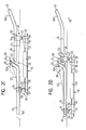
- Fig. 2A - 2D
- schematische Draufsichten auf die Schiebetür von Fig.1 in verschiedenen Schließzuständen, die von (A) ganz geschlossen bis (D) ganz offen reichen.
- Fig. 1
- a schematic side view of a guided in two guides motor vehicle sliding door in the closed state; and
- Fig. 2A - 2D
- schematic top views of the sliding door of Figure 1 in different closed states, the (A) fully closed to (D) fully open range.
Fig. 1 zeigt die Schiebetür 10 eines Kraftfahrzeugs in einem Zustand, in
dem sie eine durch einen Türrahmen 12 begrenzte Türöffnung 14 vollständig
verschließt. Im dargestellten Ausführungsbeispiel handelt es sich
um eine rechte Tür des Fahrzeugs, auf die man von außerhalb des Fahrzeugs
blickt. Ein vorderes Ende des Fahrzeugs würde sich in der Zeichnung
rechts und ein hinteres Ende links befinden. Zum Öffnen der Türöffnung
14 muss die Schiebetür 10 nach hinten (in der Zeichnung nach
links) bewegt werden.Fig. 1 shows the sliding
Die Schiebetür 10 ist in zwei, im Wesentlichen horizontalen schienenartigen
Führungen 16, 18 verschiebbar an dem Chassis des Kraftfahrzeugs
gelagert. Eine erste, obere Führung 16 ist in einem Bereich mittlerer Höhe
des Fahrzeugs und - bezüglich der Fahrzeugorientierung - parallel versetzt
hinter einer zweiten, unteren Führung 18 angeordnet. Die vordere
zweite Führung 18 ist unterhalb der durch die Schiebetür 10 zu verschließenden
Türöffnung 14 angeordnet. The sliding
In der Schiebetür 10 ist ein Antriebsaggregat 20 untergebracht, um die
Schiebetür 10 relativ zum Chassis entlang der Führungen 16, 18 zu bewegen.
Das Antriebsaggregat 20 kann beispielsweise einen Elektromotor
zum Antreiben von einem oder mehreren, nicht gezeigten Antriebszahnrädern
aufweisen, die mit einem entsprechend ausgebildeten Gegenelement
22 in Eingriff stehen.In the sliding
Das Gegenelement 22 ist zumindest bereichsweise flexibel ausgebildet und
beim dargestellten Ausführungsbeispiel durch einen Zahnriemen gebildet,
dessen Enden fest an dem Fahrzeugchassis verankert sind. Dabei ist ein
erstes, oberes Ende 24 des Gegenelements 22 im Bereich eines - in Fahrtrichtung
gesehen - vorderen Endes 26 der hinteren oberen Führung 16
und ein zweites, unteres Ende 28 des Gegenelements 22 im Bereich eines
hinteren Endes 30 der vorderen Führung 18 befestigt.The
Zwischen seinen an dem Chassis fest verankerten Enden 24, 28 wird das
Gegenelement 22 mehrmals umgelenkt. Ausgehend von seinem oberen
Ende 24 erstreckt sich ein erster, oberer Endabschnitt 32 des Gegenelements
22 zunächst - in Fahrtrichtung gesehen - nach hinten. Durch eine
an der Schiebetür 10 drehbar gelagerte erste Umlenkrolle 34 wird das
Gegenelement 22 um 180° umgelenkt, so dass ein erster Gegenelementabschnitt
36 ausgebildet ist, der sich von der ersten Umlenkrolle 34 zum
Antriebsaggregat 20 erstreckt. Das Antriebsaggregat 20 ist in einer derartigen
Höhe an der Schiebetür 10 angebracht, dass der erste Gegenelementabschnitt
36 parallel zur ersten Führung 16 und somit im Wesentlichen
horizontal verläuft. Between its fixed to the chassis ends 24, 28 is the
Das Antriebsaggregat 20 lenkt das Gegenelement 22 seinerseits derart
um, dass sich ein zweiter Gegenelementabschnitt 38 nach vorne und
schräg unten in Richtung eines vorderen Endes 40 der unteren Führung
18 erstreckt. Der Winkel, den der zweite Gegenelementabschnitt 38 mit
dem ersten Gegenelementabschnitt 36 einschließt, beträgt im dargestellten
Ausführungsbeispiel ungefähr 130°. Da der Winkel von der Breite der
Schiebetür 10 und von dem Vertikalabstand der Führungen 16, 18 zueinander
abhängt, kann er auch von 130° verschiedene Werte zwischen 90°
und 180° einnehmen.The
In einem vorderen unteren Eckbereich der Schiebetür 10 ist eine zweite
Umlenkrolle 42 an der Schiebetür vorgesehen. Diese zweite Umlenkrolle
42 lenkt den schräg verlaufenden zweiten Gegenelementabschnitt 38 in
einen parallel zur unteren Führung 18 und somit im Wesentlichen horizontal
verlaufenden zweiten, unteren Endabschnitt 44 des Gegenelements
22 um. Wie voranstehend bereits erwähnt wurde, ist das untere Ende 28
des Gegenelements 22, d.h. der untere Endabschnitt 44 des Gegenelements
22, im Bereich des hinteren Endes 30 der unteren Führung 18 fest
am Chassis verankert.In a front lower corner region of the sliding
Wie den Fig. 2A bis 2D zu entnehmen ist, ist die Schiebetür 10 mit Hilfe
von Lagermitteln 46, 48 verschiebbar in den Führungen 16, 18 gehalten.
Ein hinteres, oberes Lagermittel 46 greift in die obere Führung 16 ein, und
ein vorderes, unteres Lagermittel 48 greift in die untere Führung 18 ein.
Die Lagermittel 46, 48 weisen jeweils ein Schwenkteil 50 auf, das gelenkig
mit einem Ansatz 52 der Schiebetür 10 verbunden ist. An der dem Ansatz
52 entgegengesetzten Seite jedes Schwenkteils 50 sind jeweils zwei Rollen
54 vorgesehen, die entsprechend in der oberen Führung 16 und unteren
Führung 18 geführt sind.As can be seen in FIGS. 2A to 2D, the sliding
Damit eine Außenfläche 56 der Schiebetür 10 im geschlossenen Zustand
der Schiebetür bündig mit der die Türöffnung 14 umgebenden Karosserie
des Kraftfahrzeugs abschließt, weisen die Führungen 16, 18 jeweils einen
vorderen Endabschnitt 16A, 18A auf, der in Richtung des Fahrzeuginneren
abgewinkelt ist.So that an
Im geschlossenen Zustand befindet sich die Schiebetür 10 in ihrer - in
Fahrtrichtung gesehen - vordersten Position (Fig. 2A). In dieser Position
befinden sich die Lagermittel 46, 48 jeweils in den Endbereichen der
Vorderabschnitte 16A, 18A der Führungen 16, 18.When closed, the sliding
Die Umlenkrollen 34, 42 für das Gegenelement 22 sind im Bereich der
gelenkigen Verbindung zwischen Schwenkteil 50 und Ansatz 52 der Lagermittel
46, 48 angeordnet. Vorzugsweise dient eine Gelenkachse 58 des
aus Schwenkteil 50 und Ansatz 52 gebildeten Gelenks gleichzeitig als
Lagerachse für die Umlenkrollen 34, 42.The
Wie in den Fig. 2A bis 2D gezeigt ist, wird das Gegenelement 22 durch die
Umlenkrollen 34, 42 nicht nur innerhalb einer vertikalen, zur Schiebetür
10 im Wesentlichen parallelen Ebene umgelenkt, sondern auch in einer
dazu senkrechten, d.h. horizontalen Ebene. Da die Umlenkrollen 34, 42
einen größeren Abstand zu der Außenfläche 56 der Schiebetür 10 als das
Antriebsaggregat 20 aufweisen, verlaufen die Gegenelementabschnitte 36,
38 zwischen dem Antriebsaggregat 20 und den Umlenkrollen 34, 42 nicht
parallel zur Schiebetür 10 sondern schräg dazu in Richtung des Fahrzeuginneren.
Das obere Ende 24 des Gegenelements 22 ist im Bereich des
vorderen Endes 26 der oberen Führung 16 an einer C-Säule 60 der Fahrzeugkarosserie
62 verankert. Das untere Ende 28 des Gegenelements 22
ist im Bereich des hinteren Endes 30 der unteren Führung 18 an dem
Chassis des Fahrzeugs befestigt.As shown in Figs. 2A to 2D, the
Nachfolgend wird die automatische Betätigung der Schiebetür 10 anhand
von Fig. 2A bis 2D näher erläutert. Als Ausgangspunkt dient dabei der in
Fig. 2A gezeigte geschlossene Zustand der Schiebetür 10, welcher der
Situation von Fig. 1 entspricht.Hereinafter, the automatic operation of the sliding
Wenn das Antriebsaggregat 20 zum Öffnen der Schiebetür 10 aktiviert
wird, so wirkt das Antriebsaggregat 20 derart mit dem Gegenelement 22
zusammen, dass sich das Antriebsaggregat 20 an dem Gegenelement 22
entlang zieht. Da das Gegenelement 22 fest am Fahrzeugchassis verankert
ist und es sich deshalb in Bewegungsrichtung der Schiebetür 10 relativ
zum Fahrzeugchassis nicht wesentlich bewegen kann, bewegt sich das
Antriebsaggregat 20 bei seiner Aktivierung relativ zum Gegenelement 22
und somit relativ zum Fahrzeugchassis. Wegen der Befestigung des Antriebsaggregats
20 in der Schiebetür 10 wird bei der Aktivierung des
Antriebsaggregats 20-folglich auch die Schiebetür 10 relativ zum Fahrzeugchassis
bewegt.When the
Während des in Fig. 2A bis 2D gezeigten Vorgangs des Öffnens der Schiebetür
10 wird die Schiebetür 10 - in Fahrtrichtung gesehen - nach hinten
(in den Figuren nach links) bewegt. Dabei bewegen sich die Lagermittel
46, 48 der Schiebetür 10 in Richtung der hinteren Enden der Führungen
16, 18, bis sie im vollständig geöffneten Zustand der Schiebetür 10, der in
Fig. 2D gezeigt ist, jeweils am hinteren Ende der Führungen 16, 18 angelangt
sind. Während des Öffnungsvorgangs vergrößert sich der Abstand
zwischen der oberen Umlenkrolle 34 und dem Verankerungspunkt des
oberen Endes 24 des Gegenelements 22. Da die Gesamtlänge des Gegenelements
22 fest vorgegeben ist, nimmt im Gegenzug der Abstand zwischen
der unteren Umlenkrolle 42 und dem Verankerungspunkt des
unteren Endes 28 des Gegenelements 22 ab. Während die Länge des
unteren Endabschnitts 44 also immer kürzer wird, wird der obere Endabschnitt
32 immer länger.During the process of opening the sliding door shown in Figs. 2A to
Wie aus den Fig. 2C und 2D in Zusammenschau mit Fig. 1 zu entnehmen
ist, verläuft der erste Endabschnitt 32 des Gegenelements 22 innerhalb
der oberen Führung 16. Aufgrund des stark abgewinkelten Vorderabschnitts
16A der Führung 16 gerät der Endabschnitt 32 des Gegenelements
22 im Krümmungsbereich der Führung 16 mit einer Innenwand
der Führung 16 in Kontakt, wenn die Schiebetür 10 einen ungefähr halboffenen
Zustand erreicht hat (Fig. 2C). Da das Gegenelement 22 aber fest
am Chassis verankert ist, kann es sich nicht in Bewegungsrichtung der
Schiebetür 10 relativ zum Chassis bewegen und somit nicht an der Innenwand
der Führung 16 entlang schleifen. Es werden folglich keine
unerwünschten Reibungskräfte erzeugt. Die Berührung von Gegenelement
22 und Führung 16 im Bereich der Krümmung der Führung 16 ist daher
unkritisch.As can be seen from FIGS. 2C and 2D in conjunction with FIG
is, the
Der Schließvorgang der Schiebetür 10 erfolgt entsprechend in umgekehrter
Richtung, wobei sich der untere Endabschnitt 44 des Gegenelements
22 bei einer Bewegung der Schiebetür 10 - in Fahrtrichtung
gesehen - nach vorne (nach rechts in der Zeichnung) verlängert und sich der obere
Endabschnitt 32 entsprechend verkürzt.The closing operation of the sliding
Bei dem dargestellten Ausführungsbeispiel ist die erste Führung 16 im
Bereich einer mittleren Höhe des Fahrzeugs und - bezüglich der Fahrzeugorientierung
- hinter der Türöffnung 14 und die zweite Führung 18
unterhalb der Türöffnung 14 angeordnet, so dass die Schiebetür 10 zum
Öffnen der Türöffnung 14 nach hinten geschoben wird.In the illustrated embodiment, the
Die erste Führung kann aber auch vor der Türöffnung 14 angeordnet sein,
so dass das Öffnen der Tür durch eine Bewegung der Schiebetür nach
vorne, d.h. also in Fahrtrichtung zu erfolgen hätte. Ebenso wäre es möglich,
die zweite Führung nicht unterhalb der Türöffnung 14 sondern oberhalb
davon anzuordnen. Die erste Führung muss darüber hinaus nicht in
einem Bereich einer mittleren Höhe des Fahrzeugs angeordnet sein. Sie
könnte gleichermaßen im Bereich der Höhe einer oberen oder unteren
Begrenzung der Türöffnung vorgesehen sein.The first guide can also be arranged in front of the
Denkbar wäre außerdem eine Anordnung mit insgesamt drei Führungen, nämlich einer Führung vor oder hinter der Türöffnung und jeweils einer Führung oberhalb und unterhalb der Türöffnung. Also conceivable would be an arrangement with a total of three guides, namely a guide in front of or behind the door opening and one each Guide above and below the door opening.
- 1010
- Schiebetürsliding door
- 1212
- Türrahmendoorframe
- 1414
- Türöffnungdoorway
- 1616
- Führungguide
- 16A16A
- Vorderabschnittfront section
- 1818
- Führungguide
- 18A18A
- Vorderabschnittfront section
- 2020
- Antriebsaggregatpower unit
- 2222
- Gegenelementcounter-element
- 2424
- GegenelementendeCounter-element end
- 2626
- Führungsendelead end
- 2828
- GegenelementendeCounter-element end
- 3030
- Führungsendelead end
- 3232
- Endabschnittend
- 3434
- Umlenkrolleidler pulley
- 3636
- GegenelementabschnittAgainst element portion
- 3838
- GegenelementabschnittAgainst element portion
- 4040
- Führungsendelead end
- 4242
- Umlenkrolleidler pulley
- 4444
- Endabschnittend
- 4646
- Lagermittelbearing means
- 4848
- Lagermittelbearing means
- 5050
- Schwenkteilpivoting part
- 5252
- Ansatzapproach
- 5454
- Rollenroll
- 5656
- Außenflächeouter surface
- 5858
- Gelenkachsejoint axis
- 6060
- C-SäuleC-pillar
- 6262
- Karosseriebody
Claims (13)
dadurch gekennzeichnet, dass das Antriebsaggregat (20) zum Bewegen der Schiebetür (10) mit einem am Chassis fest verankerten Gegenelement (22) zusammenwirkt.Device according to claim 1,
characterized in that the drive unit (20) for moving the sliding door (10) cooperates with a firmly anchored to the chassis counter element (22).
dadurch gekennzeichnet, dass das Gegenelement (22) ein Seil, einen Riemen oder eine Kette aufweist, dessen bzw. deren Enden (24, 28) fest mit dem Fahrzeugchassis verbunden sind.Device according to claim 2,
characterized in that the counter-element (22) comprises a rope, a belt or a chain whose or the ends (24, 28) are fixedly connected to the vehicle chassis.
dadurch gekennzeichnet, dass die Enden (24, 28) des Gegenelements (22) jeweils im Bereich der Führungen (16, 18) an dem Fahrzeugchassis befestigt sind. Device according to claim 3,
characterized in that the ends (24, 28) of the counter-element (22) are respectively fixed in the region of the guides (16, 18) on the vehicle chassis.
dadurch gekennzeichnet, dass ein erstes Ende (24) des Gegenelements (22) im Bereich eines in Fahrtrichtung gesehen - vorderen Endes (26) einer ersten Führung (16) und ein zweites Ende (28) des Gegenelements (22) im Bereich eines hinteren Endes (30) einer zweiten Führung (18) befestigt ist.Apparatus according to claim 3 or 4,
characterized in that a first end (24) of the counter element (22) in the region of a seen in the direction of travel - front end (26) of a first guide (16) and a second end (28) of the counter element (22) in the region of a rear end (30) of a second guide (18) is attached.
dadurch gekennzeichnet, dass das Antriebsaggregat (20) ein Umlenkelement für das Gegenelement (22) bildet, wobei im Bereich des Antriebsaggregats (20) insbesondere ein erster Gegenelementabschnitt (36) sich zumindest annähernd horizontal in Richtung der ersten Führung (16) erstreckt und ein zweiter Gegenelementabschnitt (38) sich schräg dazu in Richtung der zweiten Führung (18) erstreckt.Device according to one of claims 2 to 5,
characterized in that the drive unit (20) forms a deflection element for the counter element (22), wherein in the region of the drive assembly (20), in particular a first counter element section (36) extends at least approximately horizontally in the direction of the first guide (16) and a second Counter element section (38) extends obliquely thereto in the direction of the second guide (18).
- dadurch gekennzeichnet, dass eine hintere und eine vordere Umlenkeinrichtung (34, 42), insbesondere Umlenkrolle, zum Umlenken des Gegenelements (22) an der Schiebetür (10) im Bereich von in die Führungen (16, 18) eingreifenden Lagermitteln (46, 48) der Schiebetür (10) vorgesehen sind.Device according to one of claims 2 to 6,
- characterized in that a rear and a front deflection device (34, 42), in particular deflection roller, for deflecting the counter element (22) on the sliding door (10) in the region of engaging in the guides (16, 18) bearing means (46, 48 ) of the sliding door (10) are provided.
dadurch gekennzeichnet, dass durch einen hinteren Befestigungspunkt (24) des Gegenelements (22) an dem Chassis und die hintere Umlenkeinrichtung (34) ein hinterer Endabschnitt (32) des Gegenelements (22) und durch einen vorderen Befestigungspunkt (28) des Gegenelements (22) an dem Chassis und die vordere Umlenkeinrichtung (42) ein vorderer Endabschnitt (44) des Gegenelements (22) gebildet ist, wobei durch Betätigung des Antriebsaggregats (20) der hintere Endschnitt (32) verkürzbar bzw. verlängerbar und der vordere Endabschnitt (44) entsprechend verlängerbar bzw. verkürzbar ist.Device according to one of claims 2 to 7,
characterized in that by a rear attachment point (24) of the counter element (22) on the chassis and the rear deflector (34) has a rear end portion (32) of the counter element (22) and by a front attachment point (28) of the counter element (22) on the chassis and the front deflector (42) a front end portion (44) of the counter-element (22) is formed, wherein by actuation of the drive unit (20) of the rear end section (32) shortened or extendable and the front end portion (44) accordingly can be extended or shortened.
dadurch gekennzeichnet, dass die erste Führung (16) in einem Bereich mittlerer Höhe des Fahrzeugs und - in Fahrtrichtung gesehen - parallel versetzt hinter der zweiten Führung (18) angeordnet ist und dass die zweite Führung (18) unterhalb einer durch die Schiebetür (10) zu verschließenden Türöffnung (14) angeordnet ist.Device according to one of the preceding claims,
characterized in that the first guide (16) in a region of medium height of the vehicle and - seen in the direction of travel - parallel offset behind the second guide (18) is arranged and that the second guide (18) below a through the sliding door (10) is arranged to be closed door opening (14).
dadurch gekennzeichnet, dass sich das Antriebsaggregat (20) zum Bewegen der Schiebetür (10) an einem fest an dem Chassis verankerten und insbesondere flexiblen Gegenelement (22) entlang voranbewegt.Method according to claim 10,
characterized in that the drive unit (20) for moving the sliding door (10) on a fixedly anchored to the chassis and in particular flexible counter element (22) moves along.
dadurch gekennzeichnet, dass das Gegenelement (22) durch das Antriebsaggregat (20) und durch eine an der Schiebetür (10) vorgesehene - in Fahrtrichtung gesehen - hintere und vordere Umlenkeinrichtung (34, 42) umgelenkt wird.Method according to claim 11,
characterized in that the counter element (22) by the drive unit (20) and by a on the sliding door (10) provided - viewed in the direction of travel - rear and front deflection (34, 42) is deflected.
dadurch gekennzeichnet, dass bei Betätigung des Antriebsaggregats (20) ein hinterer Endabschnitt (32) des Gegenelements (22) verkürzt bzw. verlängert und ein vorderer Endabschnitt (44) des Gegenelements (22) verlängert bzw. verkürzt wird.Method according to claim 11 or 12,
characterized in that upon actuation of the drive unit (20) a rear end portion (32) of the counter-element (22) is shortened or extended and a front end portion (44) of the counter-element (22) is extended or shortened.
Applications Claiming Priority (4)
| Application Number | Priority Date | Filing Date | Title |
|---|---|---|---|
| GBGB0215691.7A GB0215691D0 (en) | 2002-07-08 | 2002-07-08 | Power sliding door system |
| GB0215691 | 2002-07-08 | ||
| DE2002156181 DE10256181A1 (en) | 2002-07-08 | 2002-12-02 | Device for the automatic operation of a motor vehicle sliding door for busses and minivans has an internal drive to move the door along guide rails attached to the chassis |
| DE10256181 | 2002-12-02 |
Publications (2)
| Publication Number | Publication Date |
|---|---|
| EP1380718A1 true EP1380718A1 (en) | 2004-01-14 |
| EP1380718B1 EP1380718B1 (en) | 2005-04-06 |
Family
ID=29737630
Family Applications (1)
| Application Number | Title | Priority Date | Filing Date |
|---|---|---|---|
| EP20030014620 Expired - Fee Related EP1380718B1 (en) | 2002-07-08 | 2003-06-26 | Device for automatically actuating a sliding door of a vehicle |
Country Status (1)
| Country | Link |
|---|---|
| EP (1) | EP1380718B1 (en) |
Cited By (2)
| Publication number | Priority date | Publication date | Assignee | Title |
|---|---|---|---|---|
| EP1512822A1 (en) * | 2003-09-08 | 2005-03-09 | Kiekert Aktiengesellschaft | Sliding door drive unit for the sliding door of a vehicle |
| EP2076648A2 (en) * | 2006-09-26 | 2009-07-08 | Strattec Power Access LLC | Apparatus and method for providing a sliding door mechanism |
Families Citing this family (1)
| Publication number | Priority date | Publication date | Assignee | Title |
|---|---|---|---|---|
| DE102017120025A1 (en) | 2017-08-31 | 2019-02-28 | Kiekert Ag | Method for actuating a motor vehicle sliding door |
Citations (3)
| Publication number | Priority date | Publication date | Assignee | Title |
|---|---|---|---|---|
| US4887390A (en) * | 1987-12-18 | 1989-12-19 | Masco Industries, Inc. | Powered sliding door opener/closer for vehicles |
| US5536061A (en) * | 1994-12-05 | 1996-07-16 | Chrysler Corporation | Automotive vehicle body with powered sliding side door |
| US6321488B1 (en) * | 1999-03-05 | 2001-11-27 | Atoma International Corp. | Power sliding vehicle door |
-
2003
- 2003-06-26 EP EP20030014620 patent/EP1380718B1/en not_active Expired - Fee Related
Patent Citations (3)
| Publication number | Priority date | Publication date | Assignee | Title |
|---|---|---|---|---|
| US4887390A (en) * | 1987-12-18 | 1989-12-19 | Masco Industries, Inc. | Powered sliding door opener/closer for vehicles |
| US5536061A (en) * | 1994-12-05 | 1996-07-16 | Chrysler Corporation | Automotive vehicle body with powered sliding side door |
| US6321488B1 (en) * | 1999-03-05 | 2001-11-27 | Atoma International Corp. | Power sliding vehicle door |
Cited By (4)
| Publication number | Priority date | Publication date | Assignee | Title |
|---|---|---|---|---|
| EP1512822A1 (en) * | 2003-09-08 | 2005-03-09 | Kiekert Aktiengesellschaft | Sliding door drive unit for the sliding door of a vehicle |
| EP2076648A2 (en) * | 2006-09-26 | 2009-07-08 | Strattec Power Access LLC | Apparatus and method for providing a sliding door mechanism |
| US8127497B2 (en) | 2006-09-26 | 2012-03-06 | Strattec Power Access Llc | Apparatus and method for providing a sliding door mechanism |
| EP2076648A4 (en) * | 2006-09-26 | 2013-05-22 | Witte Automotive Gmbh | Apparatus and method for providing a sliding door mechanism |
Also Published As
| Publication number | Publication date |
|---|---|
| EP1380718B1 (en) | 2005-04-06 |
Similar Documents
| Publication | Publication Date | Title |
|---|---|---|
| WO2006061285A1 (en) | Sliding door for motor vehicles and method for mounting the same | |
| EP3097012B1 (en) | Device for opening an aircraft door | |
| EP3052728B1 (en) | Sliding door device for a lateral opening of a vehicle, and vehicle with sliding door device | |
| DE202004014652U1 (en) | Door for a vehicle comprises a window blind with a blind path which moves parallel to the window pane using a mechanism a part of which is guided on the window lifter guide rail | |
| EP2329976B1 (en) | Sliding door for a vehicle | |
| DE2507893C3 (en) | Window lifter for vertically subdivided motor vehicle sliding windows | |
| EP0720927A1 (en) | Vehicle roof provided with a roof panel opened by tilting | |
| DE102011085177B4 (en) | Drive system for a motor vehicle roof system | |
| EP0890011A1 (en) | Revolving door | |
| EP2338715B1 (en) | Sliding door for a vehicle | |
| DE10257673B4 (en) | Closure device provided in the body of a vehicle opening, and corresponding vehicle | |
| DE202005007984U1 (en) | Sliding double door system especially for public transport vehicle has separate drive spindles linked by clutch | |
| DE19654558C2 (en) | sunroof | |
| EP1380718B1 (en) | Device for automatically actuating a sliding door of a vehicle | |
| DE102007035072B4 (en) | Roller blind for a motor vehicle side window with window dividing web | |
| DE10254774B4 (en) | vehicle roof | |
| DE10256181A1 (en) | Device for the automatic operation of a motor vehicle sliding door for busses and minivans has an internal drive to move the door along guide rails attached to the chassis | |
| EP1488977B1 (en) | Plugging and sliding door for a vehicle. | |
| WO2006063565A1 (en) | Blind for a vehicle window | |
| WO2006084429A1 (en) | Motor vehicle door arrangement | |
| DE102005061978B3 (en) | Hinge device for vehicle flaps and doors has two hinge arms with one end of second arm remote from rotational axis connected to first arm to move in longitudinal direction of latter when both arms are rotated | |
| EP0064135A1 (en) | Window regulator | |
| DE102006014224A1 (en) | Motor vehicle e.g. passenger car, door, has bearings permitting movement of door from plane recognizing closed position of door in inner side of lateral door section of motor vehicle body and displacement in vehicle longitudinal direction | |
| DE19633645C1 (en) | Vehicle roof with cover over opening | |
| DE102021131573A1 (en) | Vehicle roof system with a roof opening |
Legal Events
| Date | Code | Title | Description |
|---|---|---|---|
| PUAI | Public reference made under article 153(3) epc to a published international application that has entered the european phase |
Free format text: ORIGINAL CODE: 0009012 |
|
| AK | Designated contracting states |
Kind code of ref document: A1 Designated state(s): AT BE BG CH CY CZ DE DK EE ES FI FR GB GR HU IE IT LI LU MC NL PT RO SE SI SK TR |
|
| AX | Request for extension of the european patent |
Extension state: AL LT LV MK |
|
| 17P | Request for examination filed |
Effective date: 20040218 |
|
| 17Q | First examination report despatched |
Effective date: 20040323 |
|
| GRAP | Despatch of communication of intention to grant a patent |
Free format text: ORIGINAL CODE: EPIDOSNIGR1 |
|
| AKX | Designation fees paid |
Designated state(s): DE FR GB IT |
|
| GRAS | Grant fee paid |
Free format text: ORIGINAL CODE: EPIDOSNIGR3 |
|
| GRAA | (expected) grant |
Free format text: ORIGINAL CODE: 0009210 |
|
| AK | Designated contracting states |
Kind code of ref document: B1 Designated state(s): DE FR GB IT |
|
| RBV | Designated contracting states (corrected) |
Designated state(s): DE FR GB IT |
|
| REG | Reference to a national code |
Ref country code: GB Ref legal event code: FG4D Free format text: NOT ENGLISH |
|
| GBT | Gb: translation of ep patent filed (gb section 77(6)(a)/1977) |
Effective date: 20050406 |
|
| REG | Reference to a national code |
Ref country code: IE Ref legal event code: FG4D Free format text: LANGUAGE OF EP DOCUMENT: GERMAN |
|
| REF | Corresponds to: |
Ref document number: 50300422 Country of ref document: DE Date of ref document: 20050512 Kind code of ref document: P |
|
| PLBI | Opposition filed |
Free format text: ORIGINAL CODE: 0009260 |
|
| ET | Fr: translation filed | ||
| PLAX | Notice of opposition and request to file observation + time limit sent |
Free format text: ORIGINAL CODE: EPIDOSNOBS2 |
|
| 26 | Opposition filed |
Opponent name: BROSE SCHLIE SYSTEME GMBH & CO. KG Effective date: 20060106 |
|
| PLBB | Reply of patent proprietor to notice(s) of opposition received |
Free format text: ORIGINAL CODE: EPIDOSNOBS3 |
|
| PGFP | Annual fee paid to national office [announced via postgrant information from national office to epo] |
Ref country code: IT Payment date: 20080624 Year of fee payment: 6 |
|
| PGFP | Annual fee paid to national office [announced via postgrant information from national office to epo] |
Ref country code: FR Payment date: 20080617 Year of fee payment: 6 |
|
| PGFP | Annual fee paid to national office [announced via postgrant information from national office to epo] |
Ref country code: GB Payment date: 20080702 Year of fee payment: 6 |
|
| PLCK | Communication despatched that opposition was rejected |
Free format text: ORIGINAL CODE: EPIDOSNREJ1 |
|
| PLBN | Opposition rejected |
Free format text: ORIGINAL CODE: 0009273 |
|
| STAA | Information on the status of an ep patent application or granted ep patent |
Free format text: STATUS: OPPOSITION REJECTED |
|
| 27O | Opposition rejected |
Effective date: 20090308 |
|
| GBPC | Gb: european patent ceased through non-payment of renewal fee |
Effective date: 20090626 |
|
| REG | Reference to a national code |
Ref country code: FR Ref legal event code: ST Effective date: 20100226 |
|
| PG25 | Lapsed in a contracting state [announced via postgrant information from national office to epo] |
Ref country code: FR Free format text: LAPSE BECAUSE OF NON-PAYMENT OF DUE FEES Effective date: 20090630 |
|
| PG25 | Lapsed in a contracting state [announced via postgrant information from national office to epo] |
Ref country code: GB Free format text: LAPSE BECAUSE OF NON-PAYMENT OF DUE FEES Effective date: 20090626 |
|
| PG25 | Lapsed in a contracting state [announced via postgrant information from national office to epo] |
Ref country code: IT Free format text: LAPSE BECAUSE OF NON-PAYMENT OF DUE FEES Effective date: 20090626 |
|
| PGFP | Annual fee paid to national office [announced via postgrant information from national office to epo] |
Ref country code: DE Payment date: 20190830 Year of fee payment: 17 |
|
| REG | Reference to a national code |
Ref country code: DE Ref legal event code: R119 Ref document number: 50300422 Country of ref document: DE |
|
| PG25 | Lapsed in a contracting state [announced via postgrant information from national office to epo] |
Ref country code: DE Free format text: LAPSE BECAUSE OF NON-PAYMENT OF DUE FEES Effective date: 20210101 |