EP1380458A2 - Fahrzeugdach - Google Patents
Fahrzeugdach Download PDFInfo
- Publication number
- EP1380458A2 EP1380458A2 EP03015487A EP03015487A EP1380458A2 EP 1380458 A2 EP1380458 A2 EP 1380458A2 EP 03015487 A EP03015487 A EP 03015487A EP 03015487 A EP03015487 A EP 03015487A EP 1380458 A2 EP1380458 A2 EP 1380458A2
- Authority
- EP
- European Patent Office
- Prior art keywords
- wind deflector
- flexible element
- vehicle roof
- roof
- roof according
- Prior art date
- Legal status (The legal status is an assumption and is not a legal conclusion. Google has not performed a legal analysis and makes no representation as to the accuracy of the status listed.)
- Withdrawn
Links
- 230000008878 coupling Effects 0.000 claims description 8
- 238000010168 coupling process Methods 0.000 claims description 8
- 238000005859 coupling reaction Methods 0.000 claims description 8
- 238000006073 displacement reaction Methods 0.000 description 3
- 210000001364 upper extremity Anatomy 0.000 description 3
- 238000009434 installation Methods 0.000 description 2
- 230000036316 preload Effects 0.000 description 2
- 238000010276 construction Methods 0.000 description 1
- 230000001419 dependent effect Effects 0.000 description 1
Images


Classifications
-
- B—PERFORMING OPERATIONS; TRANSPORTING
- B60—VEHICLES IN GENERAL
- B60J—WINDOWS, WINDSCREENS, NON-FIXED ROOFS, DOORS, OR SIMILAR DEVICES FOR VEHICLES; REMOVABLE EXTERNAL PROTECTIVE COVERINGS SPECIALLY ADAPTED FOR VEHICLES
- B60J7/00—Non-fixed roofs; Roofs with movable panels, e.g. rotary sunroofs
- B60J7/22—Wind deflectors for open roofs
Definitions
- the invention relates to a vehicle roof with at least one lid, which for optionally closing and at least partially exposing a roof opening is displaceable with one in the area of the front edge of the roof opening arranged wind deflector that around a roof-fixed axis between a lowered position and a fully flipped position pivoted and is resiliently biased towards the fully extended position and the when closing the lid is lowered against spring force, as well as with a Actuating device for setting intermediate positions of the wind deflector, wherein the adjusting device has at least one hold-down against which the Wind deflector when released for an opening movement by means of the spring force is held, and has an adjustment mechanism by means of which the hold-down device height can be adjusted to specify the intermediate positions of the wind deflector.
- a generic vehicle roof is known from DE 199 58 742 A1.
- the actuator is provided with a lever mechanism has two mirror-symmetrical rockers, one end of each one Forms stop for the wind deflector and the other end to one Control lever is articulated, which sits on an output shaft of the actuator.
- the Known solution requires one in the area of the front edge of the roof opening relatively large installation space, which is contrary to the desire that Make the roof opening as large as possible.
- This object is achieved in that the hold-down from one end connected to the wind deflector at least one flexible element is formed, the other end with a roof-mounted component is connected that the adjustment mechanism at one between these ends lying part of the flexible element attacks, and that by pressing the Adjustment mechanism the distance between the two ends of the flexible element is changeable.
- the vehicle roof according to the invention has a particularly simple mechanism compact design.
- the wind deflector adjusting device according to the invention can as a whole saves space in the area of the front edge of the roof opening accommodate. Furthermore, the wind deflector adjusting device is relative low friction losses. This is enough for an assigned Actuator a comparatively low engine power.
- the flexible element can simply be used as a webbing, rope, wire or the like be trained.
- Roof-mounted component is a front part of a roof frame that covers the edge of the Engages under the roof opening at least along part of its extent.
- a particularly robust construction is obtained if the adjustment mechanism in a further embodiment of the invention a carriage and at least one over the slide adjustable, interacting with the flexible element Has pressure element.
- the sled is expediently transverse to the direction of travel adjustable.
- a separate servomotor can be used to adjust the slide be provided, which can be designed as a linear motor. But it can also Means can be provided that a rotating motor movement in a Implement linear movement of the slide.
- the tour can simply be one in one have roof-shaped component formed passage opening, with the wall the flexible member is engaged at a location between the Coupling point of the flexible element on the wind deflector and the Point of engagement of the adjustment mechanism with the flexible element.
- This Passage opening can be conveniently in a rib in the front part of the Roof frame to be formed.
- the adjustment mechanism Preferably, several, in particular two, flexible elements adjustable. This reduces the effort keep it particularly low for the adjustment mechanism, while maintaining an exact Setting the wind deflector with respect to the vehicle roof is ensured. It is understood that under certain circumstances a single, preferably in the middle attacking the wind deflector or a wind deflector blade, flexible element can suffice. On the other hand, if necessary more than two flexible elements can be provided that are spaced apart lying areas with the wind deflector (the wind deflector blade and / or Wind deflector arms) are coupled. When using two or more flexible elements, it is basically also possible to use any flexible element assign your own adjustment mechanism.
- the maximum effective length of the flexible one or more is also advantageous Elements or elements adjustable. This way, for one Precisely defined initial orientation of the wind deflector in relation to the Vehicle roof.
- Wind deflector 16 which in the exemplary embodiment shown is parallel to the front deflector edge aligned wind deflector blade 17 and two has lateral wind deflector arms 18, which are attached to a roof-mounted joint 19 a pivot axis extending in the transverse direction of the roof are pivotally mounted.
- the wind deflector blade 17 is immersed in a lowered position (rest position) under the cover 10 into one of a front part 20 of a roof frame 21 confined space 22. In the fully extended position shown in FIG the wind deflector blade 17 above the roof level.
- an actuator 24 the total also in the area of the front edge 15 of the roof opening 11 is arranged, it can be ensured that the wind deflector 16 Intermediate positions between the rest position and the fully extended position occupies.
- the wind deflector 16 is resiliently biased in the opening direction, e.g. by means of Leaf springs trained extension springs 25, which from below against the Press on the wind deflector arms 18 and the wind deflector arms around the joint 19 try to pivot upwards.
- lie down Cam 26, which is adjustable together with the cover 10 and, for example, on the lid underside are attached, in the usual way from above against the Wind deflector arms 18 to the wind deflector 16 via the cover drive 12 lower against the force of the extension springs 25.
- cover 10 becomes wind deflector arms 18 through cover 10 released so that the extension springs 25 up the wind deflector 16 can pivot.
- the deployment movement of the wind deflector 16 is complete the actuating device 24 explained in more detail below.
- the specification of the size of the deployment movement of the wind deflector 16 serving adjusting device 24 in the present case has two flexible elements 28, 28 ', which in the illustrated embodiment is in the form of a wire or Have piece of rope, which are also straps or the like can act.
- the one end 29 of the flexible elements 28, 28 ' is like 6 in particular on the underside of the wind deflector blade 17 attached.
- the other end 30 of the flexible elements 28, 28 ' is with the front part 20 of the roof frame 21 connected.
- the flexible ones Elements 28, 28 'on the wind deflector blade 17 and / or on the roof frame 21 attached so that setting the maximum effective length of the elements 28 and thus an adjustment, for example, of the maximum opening height of the Wind deflector 16 is possible.
- this is End 30 through an opening 31 one attached to the frame front part 20 Holding block 32 is inserted, and it is there by means of a holding block 32 screwed clamping screw 33 or the like fixed.
- the actuating device 24 also includes an overall designated 35 Adjustment mechanism.
- the adjustment mechanism 35 has its own, that is Actuator 36 which can be actuated independently of the cover drive.
- the Adjustment mechanism 35 is also connected to the output side of servomotor 36 connected carriage 37 provided which is parallel to the front edge 15 of the Roof opening 11 is slidable.
- the servomotor 36 is useful as Linear motor designed.
- the servomotor 36 can also be used, for example a rotating output spindle that is provided with one on the carriage 37 attached spindle nut is in thread engagement.
- the carriage 37 extends under the frame front part 20, and he is in parallel guides 39, 40 with respect to the frame front part 20 in The roof can be moved to a limited extent.
- a driver 42 stands up from the carriage 37, which is in a guide opening 43 of the frame front part 20 is guided so as to be adjustable in the transverse direction of the roof (FIG. 5).
- a pressure element 45 which is also part of the adjustment mechanism 35, protrudes a coupling rod 44 with the driver 42 in drive connection.
- the Pressure element 45 has a front leg 47 and a rear leg 48, the one together with a connecting web 49, in the transverse direction of the roof seen, determine essentially the reverse U-shaped cross section.
- One in Rib 50 of the frame front part 20 extending in the transverse direction of the roof extends in the space between the two legs 47, 48.
- In the rib 50 is a cross to the wind deflector blade 17 through opening 51 for flexible Element 28 formed.
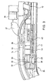
- the flexible element 28 runs from the wind deflector blade 17 front obliquely down to the bottom of the rear leg 48 of the Pressure element 45, where it is deflected in a substantially horizontal direction becomes. It then passes through the opening 51 in the rib 50. In this way the The tensile direction of the flexible element 28 to the wind deflector blade 17 is constant ) held. The flexible element 28 then extends through the opening 51 a gap 52 of the front pressure element leg 47 through to the Holding block 32. As can be seen in particular from FIG. 5, the leg 47 lies in the cover displacement direction at a distance from both the support bracket 32 and from the roof-fixed rib 50.
- the flexible element 28 When the carriage 37 is its one illustrated in the figures Assumes end position, the flexible element 28 is not from the pressure element 45 deflected. Rather, the flexible element 28 extends, as in FIG. 5 shown, straight between the bracket 32 and the rear leg 48 of the pressure element 45. The same applies to the flexible element 28 'on the other side of the wind deflector 16.
- the wind deflector 16 takes its maximum exhibited location. The latter can be chosen, for example, so that the Wind deflector blade 17 is not only overflowed by the wind, but for the purpose Minimization of booming noises a partial air flow also under the Wind deflector blade 17 is passed through.
- the Actuator 36 which can be controlled independently of the cover drive 12 is activated.
- the Carriage 37 is thereby moved in the transverse direction.
- the pressure element 45 (to the right in FIG. 2, to the left in FIGS. 3 to 5) taken.
- the pressure element 45 (to the right in FIG. 2, to the left in FIGS. 3 to 5) taken.
- the pressure element 45 exerts pressure on flexible element 28.
- the flexible Element 28 becomes the roof-fixed in the area between the passage opening 51 Rib 50 and the support bracket 32 deflected. This will make the distance between the two ends 29, 30 of the flexible element 28 is shortened.
- the adjustment movement of the carriage 37 is furthermore via a coupling element 56, which can optionally be connected in one piece to the coupling rod 44, also to a further pressure element 57 corresponding to the pressure element 45 transferred, which cooperates with the flexible element 28 '.
- the latter is in the Maintained and guided above for the element 28, and it is in the course of the adjustment of the carriage 37 in a corresponding manner deflected.
- the wind deflector 16 is therefore released after being released through the cover 10 is, by means of the extension springs 25 only by a correspondingly smaller amount issued, for example in a medium position, in which the Wind deflector blade 17 only overflows from the airstream, but not underflow becomes.
- the design can be such that the preferably electrical Actuator 36 is switched on and off by hand. Instead or as additional options can also be used for automatic control of the servomotor 36 depending on, for example, the speed of travel and / or be taken care of by the degree of opening of the cover 10.
Landscapes
- Engineering & Computer Science (AREA)
- Mechanical Engineering (AREA)
- Power-Operated Mechanisms For Wings (AREA)
- Fittings On The Vehicle Exterior For Carrying Loads, And Devices For Holding Or Mounting Articles (AREA)
- Seal Device For Vehicle (AREA)
Abstract
Description
- Fig. 1
- eine schematische Draufsicht auf den vorderen Teil des Dachrahmens und des Windabweisers eines erfindungsgemäßen Fahrzeugdaches,
- Fig. 2
- eine schematische perspektivische Teilansicht der Anordnung der Fig. 1 mit Blickrichtung von vorne links,
- Fig. 3
- in größerem Maßstab eine schematische Draufsicht auf einen Teil der Anordnung der Fig. 1,
- Fig. 4
- eine schematische perspektivische Teilansicht der Anordnung der Fig. 1 mit Blickrichtung von hinten links,
- Fig. 5
- einen Schnitt entlang der Linie C-C in Fig. 6,
- Fig. 6
- einen Schnitt entlang der Linie B-B in Fig. 4, und
- Fig. 7
- eine schematische Seitenansicht der Anordnung nach den Figuren 1 bis 6.
- 9
- feste Dachhaut
- 10
- Deckel
- 11
- Dachöffnung
- 12
- Deckelantrieb
- 13, 14
- Kabelanal
- 15
- vorderer Rand von 11
- 16
- Windabweiser
- 17
- Windabweiserblatt
- 18
- Windabweiserarm
- 19
- Gelenk
- 20
- Rahmenvorderteil
- 21
- Dachrahmen
- 22
- Raum
- 24
- Stellvorrichtung
- 25
- Ausstellfeder
- 26
- Nocken
- 28, 28'
- flexibles Element
- 29, 30
- Ende von 28
- 31
- Öffnung
- 32
- Haltebock
- 33
- Klemmschraube
- 35
- Verstellmechanik
- 36
- Stellmotor
- 37
- Schlitten
- 39, 40
- Parallelführung
- 42
- Mitnehmer
- 43
- Führungsöffnung
- 44
- Koppelstange
- 45
- Druckelement
- 47
- vorderer Schenkel von 45
- 48
- hinterer Schenkel von 45
- 49
- Verbindungssteg
- 50
- Rippe
- 51
- Durchtrittsöffnung
- 52
- Spalt
- 54
- Begrenzungswand
- 56
- Koppelelement
- 57
- Druckelement
Claims (13)
- Fahrzeugdach mit mindestens einem Deckel (10), der zum wahlweisen Verschließen und mindestens teilweisen Freilegen einer Dachöffnung (11) verschiebbar ist, mit einem im Bereich des vorderen Randes (15) der Dachöffnung angeordneten Windabweiser (16), der um eine dachfeste Achse zwischen einer abgesenkten Position und einer voll ausgestellten Position schwenkbar gelagert und in Richtung der voll ausgestellten Position federnd vorgespannt ist und der beim Schließen des Deckels gegen Federkraft abgesenkt wird, sowie mit einer Stellvorrichtung (24) zum Einstellen von Zwischenpositionen des Windabweisers, wobei die Stellvorrichtung mindestens einen Niederhalter, gegen den der Windabweiser bei Freigabe für eine Ausstellbewegung mittels der Federkraft gehalten ist, und eine Verstellmechanik (35) aufweist, mittels deren der Niederhalter zur Vorgabe der Zwischenpositionen des Windabweisers höhenverstellbar ist, dadurch gekennzeichnet, dass der Niederhalter von einem mit dem Windabweiser (16) in Verbindung stehenden Ende (29) mindestens eines flexiblen Elements (28, 28') gebildet ist, dessen anderes Ende (30) mit einem dachfesten Bauteil (20) verbunden ist, dass die Verstellmechanik (35) an einem zwischen diesen Enden liegenden Teil des flexiblen Elements angreift, und dass durch Betätigen der Verstellmechanik der Abstand zwischen den beiden Enden des flexiblen Elements änderbar ist.
- Fahrzeugdach nach Anspruch 1, dadurch gekennzeichnet, dass das flexible Element (28, 28') als Gurtband, Seil oder Draht ausgebildet ist.
- Fahrzeugdach nach einem der vorhergehenden Ansprüche, dadurch gekenrizeichnet, dass das mit dem anderen Ende des flexiblen Elements (28, 28') verbundene dachfeste Bauteil ein vorderer Teil (20) eines den Rand der Dachöffnung (11) mindestens entlang einem Teil seiner Erstreckung untergreifenden Dachrahmens (21) ist.
- Fahrzeugdach nach einem der vorhergehenden Ansprüche, dadurch gekennzeichnet, dass die Verstellmechanik (35) einen Schlitten (37) und mindestens ein über den Schlitten verstellbares, mit dem flexiblen Element (28, 28') zusammenwirkendes Druckelement (45, 57) aufweist.
- Fahrzeugdach nach Anspruch 4, dadurch gekennzeichnet, dass der Schlitten (37) quer zur Fahrtrichtung verstellbar ist.
- Fahrzeugdach nach einem der vorhergehenden Ansprüche, dadurch gekennzeichnet, dass zum Verstellen des Schlittens (37) ein eigener Stellmotor (36) vorgesehen ist.
- Fahrzeugdach nach Anspruch 6, dadurch gekennzeichnet, dass der Stellmotor (36) als Linearmotor ausgebildet ist.
- Fahrzeugdach nach Anspruch 6 oder 7, dadurch gekennzeichnet, dass der Stellmotor (36) in Abhängigkeit von der Fahrtgeschwindigkeit und/oder von dem Öffnungsgrad des Deckels (10) angesteuert ist.
- Fahrzeugdach nach einem der vorhergehenden Ansprüche, gekennzeichnet durch eine Führung (51), welche die Zugrichtung, in welcher das flexible Element (28, 28') an dem Windabweiser (16) angreift, unabhängig von der jeweiligen Stellung der Verstellmechanik (35) konstant hält.
- Fahrzeugdach nach Anspruch 9, dadurch gekennzeichnet, dass die Führung (51) eine in einem dachfesten Bauteil (50) ausgebildete Durchtrittsöffnung aufweist, mit deren Wand das flexible Element (28, 28') an einer Stelle in Eingriff steht, die zwischen der Ankoppelstelle des flexiblen Elements an dem Windabweiser (16) und der Eingriffsstelle (52) der Verstellmechanik (35) mit dem flexiblen Element liegt.
- Fahrzeugdach nach Ansprüchen 3 und 10, dadurch gekennzeichnet, dass die Durchtrittsöffnung in einer Rippe (50) in dem vorderen Teil (20) des Dachrahmens (21) ausgebildet ist.
- Fahrzeugdach nach einem der vorhergehenden Ansprüche, dadurch gekennzeichnet, dass mittels der Verstellmechanik (35) gleichzeitig mehrere flexible Elemente (28, 28') verstellbar sind.
- Fahrzeugdach nach einem der vorhergehenden Ansprüche, dadurch gekennzeichnet, dass die maximale wirksame Länge des flexiblen Elements (28, 28') justierbar ist.
Applications Claiming Priority (2)
| Application Number | Priority Date | Filing Date | Title |
|---|---|---|---|
| DE10231169 | 2002-07-10 | ||
| DE2002131169 DE10231169B4 (de) | 2002-07-10 | 2002-07-10 | Fahrzeugdach |
Publications (2)
| Publication Number | Publication Date |
|---|---|
| EP1380458A2 true EP1380458A2 (de) | 2004-01-14 |
| EP1380458A3 EP1380458A3 (de) | 2004-04-14 |
Family
ID=29723827
Family Applications (1)
| Application Number | Title | Priority Date | Filing Date |
|---|---|---|---|
| EP03015487A Withdrawn EP1380458A3 (de) | 2002-07-10 | 2003-07-09 | Fahrzeugdach |
Country Status (2)
| Country | Link |
|---|---|
| EP (1) | EP1380458A3 (de) |
| DE (1) | DE10231169B4 (de) |
Cited By (1)
| Publication number | Priority date | Publication date | Assignee | Title |
|---|---|---|---|---|
| US10583725B1 (en) * | 2018-09-28 | 2020-03-10 | Nissan North America, Inc. | Vehicle wind deflector assembly |
Families Citing this family (1)
| Publication number | Priority date | Publication date | Assignee | Title |
|---|---|---|---|---|
| DE102005002538B4 (de) * | 2005-01-19 | 2008-04-30 | Webasto Ag | Fahrzeugdach |
Citations (1)
| Publication number | Priority date | Publication date | Assignee | Title |
|---|---|---|---|---|
| DE19958742A1 (de) | 1999-12-07 | 2001-06-21 | Webasto Vehicle Sys Int Gmbh | Vorrichtung zur Beeinflussung der Luftströmung |
Family Cites Families (6)
| Publication number | Priority date | Publication date | Assignee | Title |
|---|---|---|---|---|
| JPS61169319A (ja) * | 1985-01-23 | 1986-07-31 | Mazda Motor Corp | サンル−フのデイフレクタ−昇降装置 |
| US6174025B1 (en) * | 1999-08-31 | 2001-01-16 | Daimlerchrysler Corporation | Sun roof air dam wind noise reducer |
| DE19958748B4 (de) * | 1999-12-07 | 2005-07-28 | Webasto Ag | Vorrichtung zur Beeinflussung der Luftströmung |
| FR2810592B1 (fr) * | 2000-06-27 | 2002-11-29 | Webasto Systemes Carrosserie | Systeme de deflecteur de toit ouvrant |
| DE10136922A1 (de) * | 2001-07-30 | 2003-02-20 | Webasto Vehicle Sys Int Gmbh | Windabweiser für ein Fahrzeugdach |
| DE10142047A1 (de) * | 2001-08-28 | 2003-03-20 | Arvinmeritor Gmbh | Windabweiser mit Betätigungselement für ein Schiebedachsystem |
-
2002
- 2002-07-10 DE DE2002131169 patent/DE10231169B4/de not_active Expired - Fee Related
-
2003
- 2003-07-09 EP EP03015487A patent/EP1380458A3/de not_active Withdrawn
Patent Citations (1)
| Publication number | Priority date | Publication date | Assignee | Title |
|---|---|---|---|---|
| DE19958742A1 (de) | 1999-12-07 | 2001-06-21 | Webasto Vehicle Sys Int Gmbh | Vorrichtung zur Beeinflussung der Luftströmung |
Cited By (1)
| Publication number | Priority date | Publication date | Assignee | Title |
|---|---|---|---|---|
| US10583725B1 (en) * | 2018-09-28 | 2020-03-10 | Nissan North America, Inc. | Vehicle wind deflector assembly |
Also Published As
| Publication number | Publication date |
|---|---|
| EP1380458A3 (de) | 2004-04-14 |
| DE10231169A1 (de) | 2004-01-29 |
| DE10231169B4 (de) | 2006-02-16 |
Similar Documents
| Publication | Publication Date | Title |
|---|---|---|
| DE4227400C2 (de) | Schiebedach | |
| DE19520348C1 (de) | Windabweiser | |
| DE202007002243U1 (de) | Höheneinstellvorrichtung eines Fahrzeugsitzes und damit ausgestatteter Fahrzeugsitz | |
| DE3425271A1 (de) | Fahrzeugdach | |
| DE102005033431B4 (de) | Vorrichtung zur Beeinflussung einer Luftströmung an einem öffnungsfähigen Fahrzeugdach | |
| DE69821452T2 (de) | Konstruktion eines öffnungsfähigen Fahrzeugdaches | |
| DE19626937C2 (de) | Vorrichtung zur Geräuschminderung an einer Schiebedachöffnung eines Fahrzeugs | |
| DE3129900C2 (de) | Hebeschiebedach für Kraftfahrzeuge | |
| DE10348545B4 (de) | Verstellmechanik zum Verlagern eines Deckels eines öffnungsfähigen Fahrzeugdaches | |
| DE3544941C2 (de) | ||
| DE102006023911A1 (de) | Vorrichtung zum Führen der Bewegung eines Windabweisers | |
| EP3912841A1 (de) | Dachlüfter für freizeitfahrzeug | |
| EP1193094A2 (de) | Mechanik für einen Windabweiser eines öffnungsfähigen Fahrzeugdachs | |
| WO2007147390A1 (de) | Fahrzeugdach mit windabweiser | |
| DE10237543A1 (de) | Fahrzeugdach | |
| DE60009784T2 (de) | Konstruktion eines öffnungsfähigen Fahrzeugdaches | |
| DE3922874C2 (de) | ||
| DE3823316C2 (de) | ||
| DE10221501B4 (de) | Fahrzeugdach | |
| DE10231169B4 (de) | Fahrzeugdach | |
| DE10146285B4 (de) | Fahrzeugdach | |
| DE10203848B4 (de) | Schiebedach für Fahrzeuge | |
| DE10226110B4 (de) | Fahrzeugdach | |
| EP1382473A2 (de) | Fahrzeugdach | |
| DE10344884B3 (de) | Fahrzeugdach mit einer Dachöffnung und einem Windabweiser |
Legal Events
| Date | Code | Title | Description |
|---|---|---|---|
| PUAI | Public reference made under article 153(3) epc to a published international application that has entered the european phase |
Free format text: ORIGINAL CODE: 0009012 |
|
| AK | Designated contracting states |
Kind code of ref document: A2 Designated state(s): AT BE BG CH CY CZ DE DK EE ES FI FR GB GR HU IE IT LI LU MC NL PT RO SE SI SK TR |
|
| AX | Request for extension of the european patent |
Extension state: AL LT LV MK |
|
| PUAL | Search report despatched |
Free format text: ORIGINAL CODE: 0009013 |
|
| AK | Designated contracting states |
Kind code of ref document: A3 Designated state(s): AT BE BG CH CY CZ DE DK EE ES FI FR GB GR HU IE IT LI LU MC NL PT RO SE SI SK TR |
|
| AX | Request for extension of the european patent |
Extension state: AL LT LV MK |
|
| RIC1 | Information provided on ipc code assigned before grant |
Ipc: 7B 60J 7/22 B Ipc: 7B 60J 7/20 A |
|
| 17P | Request for examination filed |
Effective date: 20040902 |
|
| AKX | Designation fees paid |
Designated state(s): DE FR GB NL |
|
| RAP1 | Party data changed (applicant data changed or rights of an application transferred) |
Owner name: WEBASTO AG |
|
| 17Q | First examination report despatched |
Effective date: 20100204 |
|
| STAA | Information on the status of an ep patent application or granted ep patent |
Free format text: STATUS: THE APPLICATION IS DEEMED TO BE WITHDRAWN |
|
| 18D | Application deemed to be withdrawn |
Effective date: 20100615 |