EP1378317A1 - Anschlagsystem für eine Werkzeugmaschine insbesondere für eine Tischkreissägemaschine - Google Patents
Anschlagsystem für eine Werkzeugmaschine insbesondere für eine Tischkreissägemaschine Download PDFInfo
- Publication number
- EP1378317A1 EP1378317A1 EP03008283A EP03008283A EP1378317A1 EP 1378317 A1 EP1378317 A1 EP 1378317A1 EP 03008283 A EP03008283 A EP 03008283A EP 03008283 A EP03008283 A EP 03008283A EP 1378317 A1 EP1378317 A1 EP 1378317A1
- Authority
- EP
- European Patent Office
- Prior art keywords
- stop
- guide rail
- stop system
- guide
- groove
- Prior art date
- Legal status (The legal status is an assumption and is not a legal conclusion. Google has not performed a legal analysis and makes no representation as to the accuracy of the status listed.)
- Granted
Links
- 229910052782 aluminium Inorganic materials 0.000 claims description 3
- XAGFODPZIPBFFR-UHFFFAOYSA-N aluminium Chemical compound [Al] XAGFODPZIPBFFR-UHFFFAOYSA-N 0.000 claims description 3
- 238000006073 displacement reaction Methods 0.000 claims description 2
- 229910052751 metal Inorganic materials 0.000 claims description 2
- 239000002184 metal Substances 0.000 claims description 2
- 238000010276 construction Methods 0.000 description 4
- 230000001419 dependent effect Effects 0.000 description 1
- 238000011161 development Methods 0.000 description 1
- 230000018109 developmental process Effects 0.000 description 1
- 230000000694 effects Effects 0.000 description 1
- 238000005516 engineering process Methods 0.000 description 1
- 238000001125 extrusion Methods 0.000 description 1
- 238000003754 machining Methods 0.000 description 1
- 238000002360 preparation method Methods 0.000 description 1
Images


Classifications
-
- B—PERFORMING OPERATIONS; TRANSPORTING
- B23—MACHINE TOOLS; METAL-WORKING NOT OTHERWISE PROVIDED FOR
- B23Q—DETAILS, COMPONENTS, OR ACCESSORIES FOR MACHINE TOOLS, e.g. ARRANGEMENTS FOR COPYING OR CONTROLLING; MACHINE TOOLS IN GENERAL CHARACTERISED BY THE CONSTRUCTION OF PARTICULAR DETAILS OR COMPONENTS; COMBINATIONS OR ASSOCIATIONS OF METAL-WORKING MACHINES, NOT DIRECTED TO A PARTICULAR RESULT
- B23Q3/00—Devices holding, supporting, or positioning work or tools, of a kind normally removable from the machine
- B23Q3/005—Guides for workpieces
- B23Q3/007—Guides for workpieces provided with measuring means allowing the positioning of the guides
-
- B—PERFORMING OPERATIONS; TRANSPORTING
- B27—WORKING OR PRESERVING WOOD OR SIMILAR MATERIAL; NAILING OR STAPLING MACHINES IN GENERAL
- B27B—SAWS FOR WOOD OR SIMILAR MATERIAL; COMPONENTS OR ACCESSORIES THEREFOR
- B27B27/00—Guide fences or stops for timber in saw mills or sawing machines; Measuring equipment thereon
- B27B27/08—Guide fences or stops for timber in saw mills or sawing machines; Measuring equipment thereon arranged adjustably, not limited to only one of the groups B27B27/02 - B27B27/06
Definitions
- the invention relates to a stop system for a machine tool, in particular for a table saw machine with the characteristics of the generic term of claim 1.
- the known stop system for a machine tool, of which the invention goes out (DE 86 15 156 U1) is set up on a table saw.
- This table saw is on the outside of the machine housing Machining side and the opposite side each a support and guide rail screwed tight, which is just as long as the machine housing.
- the carrier and guide rails run into the desired positions Work table lockable rip fence (parallel to the level of the saw blade).
- the rip fence is by means of an adjustment mechanism with quick actuation lever with the support and guide rail arranged on the processing side braced.
- the known machine tool also has in the surface of the workpiece table one parallel to the plane of the saw blade and laterally at a distance from the plane of the saw blade running guide groove for a miter fence with fence and angle adjuster.
- the angle stop can be up to 45 ° on both sides or 60 ° and can be adjusted on the workpiece table by simply pushing it in into the guide groove, with several spaced apart Guide grooves in one of the guide grooves, easily attached. For this purpose, an approximately T-shaped grooved strip is inserted into the guide groove in the Work table inserted. You can in the longitudinal direction of the guide groove with previously selected and locked angle setting of the stop ruler Advancing the workpiece in the desired angular position relative to the Saw blade can be moved lengthways.
- the teaching is based on the problem, an optimized, namely simple, stop system for a machine tool of the type in question, in particular So for a table saw machine.
- Stop ruler With angle adjuster.
- the wedge principle Clamping device serves as a longitudinal lock, whereby even when the stop ruler is locked, however, a loosened locking screw of the angle adjuster Adjustment backdrop can be pivoted.
- the stop ruler is not only by means of the angle adjuster and the locking screw in its angular position with respect to the slot bar adjustable and lockable, but it is also in the guide groove in a certain Position by tightening the slot bar with the guide slot in Lockable in the longitudinal direction.
- the rip fence should be firmly locked in a certain position because the workpiece is moved along the rip fence by one Realize a cut with a precisely specified cutting width. That’s with the additionally provided longitudinal locking of the stop ruler in the stop system the invention possible.
- the stop system shown in the drawing is for a machine tool determined and suitable.
- Machine tools of this type are machines for sawing, planing, etc., but especially table saws.
- a Such a machine tool regularly has a machine housing or a machine frame and in any case a workpiece table on which a workpiece rests and that of a table saw machine from below in a saw slot is penetrated by a circular saw blade.
- the state of the Technology from DE 86 15 156 U1 already mentioned at the beginning is also referred to are like the prior art from DE 296 06 910 U1, but also the DE 40 25 440 A1.
- the stop system initially has a C-shaped guide groove 1 and an in the guide groove 1 with play, longitudinally displaceable, T-shaped Groove strip 2 on.
- the slot bar 2 runs in the guide groove 1 with play, so that easy longitudinal movement is guaranteed. However, must the game should be so small that the groove 2 in the guide groove 1 also clean to be led.
- a stop ruler 3 is pivotally mounted on the slot bar 2.
- the stop rail 5 is fastened to the support 4 by means of two stop screws, their associated T counterparts, not recognizable in FIG. 1, in one corresponding C-groove as an extrusion profile made of metal, in particular Aluminum stop rail 5 run.
- the stop ruler 3 has, directly connected or even made in one piece with the carrier 4, an angle adjuster 7.
- the angle adjuster 7 has an adjusting link 8 and a locking screw 9.
- the illustrated embodiment shows the setting 8 as a circular arrangement, the an angular limitation of the angle setting to ⁇ 60 ° (Fig. 3) ensures. However, it doesn't have to be such an arcuate design, either a corresponding edge could form an adjustment link 8. It is essential that by means of the locking screw 9 of the angle adjuster 7 in the desired angular position can be clamped against the slot bar 2.
- the solution is such that the locking screw 9 in a threaded socket 10 is screwed into a T-center piece 11 of the groove strip 2.
- the angle adjuster 7 is on the slot bar 2 by means of a pivot bearing 12 pivoted.
- the guide groove 1 is formed in a guide rail 13 and the slot bar 2 has in its T-center piece 11 a height that is greater than the thickness of the guide rail 13 on the guide groove 1.
- the slot bar 2 projects with its T-center piece 11 upwards over the outside the guide rail 13 also.
- This construction ensures that the slot bar 2 in the guide groove 1 is then also longitudinally displaceable when the angle adjuster 7 by tightening the locking screw 9 in a certain Angular position is clamped with the slot bar 2. So you can fix the angular position of the stop ruler 3 and then use the 3 the workpiece to be sawn in the desired Shift the angular position relative to the saw blade.
- An additional longitudinal lock 14 is provided on the stop ruler 3 with the stop ruler 3 using the slot bar 2 on the guide rail 13 can be locked against longitudinal displacements.
- the longitudinal lock 14 is independent of the angle setting. Thanks to the independent longitudinal lock 14 is achieved that when the guide groove 1 at an angle of aligned about 90 ° with respect to the use of the stop system as an angle stop and the stop ruler 3 by means of the angle adjuster 7 in the middle position (0 °) is tensioned, the stop system for realizing a parallel stop can be used.
- the illustrated and preferred embodiment shows a solution to this is characterized in that the longitudinal lock 14 in a circular arc Free cut 15 of the setting link 8 is attached to the slot bar 2.
- FIG. 3. 4 shows constructively, that here in the embodiment shown the longitudinal lock 14 from a locking screw screwed into a threaded socket 16 of the groove strip 2 17 with a stop 18 and a larger diameter than the clear Width of the guide groove 1 having clamping sleeve 19, which is on the guide rail 13 sits there.
- the T-center piece 11 of the Groove strip 2 has a recess 20 around the threaded socket 16, in which the height of the T-center piece 11 of the groove strip 2 is less than the thickness the guide rail 13 on the guide groove 1. This succeeds the previously explained Function of the bracing by means of the longitudinal lock 14. You can see these relationships if one considers FIGS. 2 and 3 together.
- the illustrated embodiment shows a construction in which the locking screw 9 / threaded socket 10 for the angle adjustment, the swivel bearing 12 and the longitudinal lock 14 three separate parts of the overall construction form.
- the Swivel bearing 12 integrated with the longitudinal lock 14, so the longitudinal lock 14 practically in the place of the pivot bearing 12 in FIGS. 2 and 3 the drawing sets.
- the angle adjuster 7 would have to be tight the adapter sleeve 19 of the longitudinal lock 14 sit around, so that the adapter sleeve 19 can effectively form the pivot axis of the pivot bearing 12.
- the first is that Possibility of integrating this guide rail 13 as in the prior art the workpiece table of the machine tool. That can go up to one piece Design go.
- a guide rail becomes more common 13 then, as it were, let it into the workpiece table also the saw blade guide of the circular saw blade as a separate part in the workpiece table gets involved.
- workpiece tables with edge sides are also from the prior art attachable, screwable or pluggable guide rails known.
- this respect shows the illustrated and preferred embodiment of a separately a guide rail attachable to a workpiece table of a machine tool 13.
- This can be attached to the long side of the machine tool, whereby then the function of the angle stop is realized. It can, if appropriate Design of the machine tool, on the transverse side of the machine tool be attached, which then the stop system the rip fence realized. Appropriate preparations for machine tools for attachment Such a stop system should be aimed at.
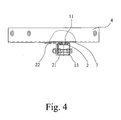
- Fig. 4 shows another embodiment, which is characterized is that the guide rail 13 is designed as a folded sheet profile is.
- Fig. 4 shows a special embodiment, which is characterized is that the clear width of the guide rail 13 by means of one or more transversely arranged cross screws 21 is adjustable. You can see the leadership effect Adjust the guide groove 1 for the T-center piece 11 of the slot bar 2.
- Fig. 4 shows in dash-dotted lines an angle rail 22 which for Workpiece table belongs to the machine tool. You can see it like the guide rail 13 can be attached on the edge.
- the invention also relates to a machine tool, in particular a machine tool Circular saw machine, with a stop system of the type described above. This is characterized in that attachment options for the guide rail 13 on the long side and the short side of the workpiece table or the housing of the machine tool are provided.
Landscapes
- Engineering & Computer Science (AREA)
- Mechanical Engineering (AREA)
- Life Sciences & Earth Sciences (AREA)
- Wood Science & Technology (AREA)
- Forests & Forestry (AREA)
- Sawing (AREA)
Abstract
Description
- Fig. 1
- in perspektivischer Ansicht ein erfindungsgemäßes Anschlagsystem für eine Werkzeugmaschine, jedoch dargestellt ohne eine Werkzeugmaschine,
- Fig. 2
- das Anschlagsystem aus Fig. 1 mit der Führungsschiene teilweise aufgeschnitten, so daß man die Nutenleiste in der Führungsnut erkennt,
- Fig. 3
- in Draufsicht das Anschlagsystem aus Fig. 1 und
- Fig. 4
- das Anschlagsystem aus Fig. 2 von links gesehen, im Bereich der Führungsschiene geschnitten.
Claims (10)
- Anschlagsystem für eine Werkzeugmaschine, insbesondere für eine Tischkreissägemaschine, mit einer C-förmigen Führungsnut (1) und einer in der Führungsnut (1) mit Spiel geführten, in Längsrichtung der Führungsnut (1) verschiebbaren T-förmigen Nutenleiste (2), mit einem an der Nutenleiste (2) schwenkbar gelagerten Anschlaglineal (3) mit einem Winkeleinsteller (7), wobei der Winkeleinsteller (7) eine Einstellkulisse (8) und eine Feststellschraube (9) aufweist, mit der die Einstellkulisse (8) gegen die Nutenleiste (2) verspannbar ist, wobei die Führungsnut (1) in einer Führungsschiene (13) ausgebildet ist, wobei die Nutenleiste (2) in einem T-Mittelstück (11) eine Höhe aufweist, die größer ist als die Dicke der Führungsschiene (13) an der Führungsnut (1), und so mit ihrem T-Mittelstück (11) nach oben über die Außenseite der Führungsschiene (13) hinausragt und wobei die Einstellkulisse (8) nur gegen das T-Mittelstück (11) der Nutenleiste (2) verspannbar ist,
dadurch gekennzeichnet, daß am Anschlaglineal (3) eine zusätzliche Längsarretierung (14) vorgesehen ist, mit der das Anschlaglineal (3) unter Nutzung der Nutenleiste (2) an der Führungsschiene (13) gegen Längsverschiebungen arretierbar ist und daß auch bei mittels der Längsarretierung (14) an der Führungsschiene (13) arretiertem Anschlaglineal (3), jedoch gelöster Feststellschraube (9), die Einstellkulisse (8) schwenkbar ist. - Anschlagsystem nach Anspruch 1, dadurch gekennzeichnet, daß die Längsarretierung (14) in einem kreisbogenförmigen Freischnitt (15) der Einstellkulisse (8) an der Nutenleiste (2) angebracht ist.
- Anschlagsystem nach Anspruch 1, dadurch gekennzeichnet daß die Längsarretierung (14) gleichzeitig die Schwenklagerung (12) des Anschlaglineals (3) bildet.
- Anschlagsystem nach einem der Ansprüche 1 bis 3, dadurch gekennzeichnet daß die Längsarretierung (14) aus einer in eine Gewindefassung (16) der Nutenleiste (2) eingeschraubten Arretierschraube (17) mit Anschlag (18) und einer einen größeren Durchmesser als die lichte Breite der Führungsnut (1) aufweisenden Spannhülse, die auf der Führungskulisse (13) aufsitzt, besteht und daß das T-Mittelstück (11) der Nutenleiste (2) um die Gewindefassung (16) herum eine Ausnehmung (20) aufweist, in der die Höhe des T-Mittelstücks (11) der Nutenleiste (2) geringer ist als die Dicke der Führungsschiene (13) an der Führungsnut (1).
- Anschlagsystem nach einem der Ansprüche 1 bis 4, dadurch gekennzeichnet daß die Führungsschiene (13) in einem Werkstücktisch einer Werkzeugmaschine ausgebildet ist.
- Anschlagsystem nach einem der Ansprüche 1 bis 4, dadurch gekennzeichnet daß die Führungsschiene (13) an einem Werkstücktisch einer Werkzeugmaschine separat anbringbar ist.
- Anschlagsystem nach einem der Ansprüche 1 bis 6, dadurch gekennzeichnet daß die Führungsschiene (13) als Aluminium-Strangpreßprofil ausgebildet ist.
- Anschlagsystem nach einem der Ansprüche 1 bis 6, dadurch gekennzeichnet daß die Führungsschiene (13) als abgekantetes Blechprofil ausgeführt ist.
- Anschlagsystem nach Anspruch 7 oder 8, dadurch gekennzeichnet daß die lichte Breite der von der Führungsschiene (13) gebildeten Führungsnut (1) mittels einer oder mehrerer quer angeordneter Querschrauben (21) einstellbar ist.
- Werkzeugmaschine, insbesondere Tischkreissägemaschine, mit einem Werkstücktisch und einem Anschlagsystem nach einem der Ansprüche 1 bis 9 oder vorbereitet für ein solches Anschlagsystem,
dadurch gekennzeichnet, daß der Werkstücktisch der Werkzeugmaschine aufweist entweder
einander kreuzende Führungsnuten für die Nutenleiste des Anschlagsystems oder mindestens je eine Führungsnut für die Nutenleiste im Werkstücktisch und Anbringungsmöglichkeiten für eine Führungsschiene mit Führungsnut an einem quer dazu verlaufenden Rand des Werkstücktisches oder
Anbringungsmöglichkeiten für die Führungsschiene des Anschlagsystems sowohl am quer verlaufenden Rand als auch am längs verlaufenden Rand des Werkstücktisches.
Applications Claiming Priority (2)
| Application Number | Priority Date | Filing Date | Title |
|---|---|---|---|
| DE20210275U DE20210275U1 (de) | 2002-07-02 | 2002-07-02 | Anschlagsystem für eine Werkzeugmaschine, insbesondere für eine Tischkreissäge |
| DE20210275U | 2002-07-02 |
Publications (2)
| Publication Number | Publication Date |
|---|---|
| EP1378317A1 true EP1378317A1 (de) | 2004-01-07 |
| EP1378317B1 EP1378317B1 (de) | 2005-07-06 |
Family
ID=7972786
Family Applications (1)
| Application Number | Title | Priority Date | Filing Date |
|---|---|---|---|
| EP03008283A Expired - Lifetime EP1378317B1 (de) | 2002-07-02 | 2003-04-09 | Anschlagsystem für eine Werkzeugmaschine insbesondere für eine Tischkreissägemaschine |
Country Status (3)
| Country | Link |
|---|---|
| EP (1) | EP1378317B1 (de) |
| AT (1) | ATE299067T1 (de) |
| DE (2) | DE20210275U1 (de) |
Cited By (3)
| Publication number | Priority date | Publication date | Assignee | Title |
|---|---|---|---|---|
| ES2304309A1 (es) * | 2007-03-26 | 2008-10-01 | Capñas Y Gomez, S.L. | Escuadra guia. |
| ES2342650A1 (es) * | 2009-01-08 | 2010-07-09 | Cañas Y Gomez S.L. | Escuadra articulada. |
| CN105290499A (zh) * | 2015-09-24 | 2016-02-03 | 广东创高幕墙门窗工程有限公司 | 全角度数字信息超高精度铝加工技术设备 |
Citations (4)
| Publication number | Priority date | Publication date | Assignee | Title |
|---|---|---|---|---|
| US1789125A (en) * | 1927-12-24 | 1931-01-13 | Clinton G Wilderson | Cut-off gauge for saws |
| WO1991000162A1 (de) * | 1989-07-01 | 1991-01-10 | Robert Bosch Gmbh | Parallel- und winkelanschlag |
| DE29513842U1 (de) * | 1995-09-01 | 1995-10-19 | Atika-Maschinenfabrik Wilhelm Pollmeier GmbH & Co, 59227 Ahlen | Tischkreissäge |
| DE10000102A1 (de) * | 1999-03-16 | 2000-09-21 | Proxxon Sa | Anschlagvorrichtung |
Family Cites Families (5)
| Publication number | Priority date | Publication date | Assignee | Title |
|---|---|---|---|---|
| DE8615156U1 (de) | 1986-06-05 | 1986-07-17 | Elektra-Beckum Lubitz & Co, 4470 Meppen | Werkzeugmaschine, insbesondere Kreissägemaschine |
| DE4025440A1 (de) | 1989-08-11 | 1991-02-14 | Ryobi Ltd | Tischsaege |
| DE9207811U1 (de) | 1992-06-10 | 1993-01-14 | Georg Ott Werkzeug- und Maschinenfabrik GmbH & Co, 7900 Ulm | Gehrungsanschlag |
| DE4231110A1 (de) | 1992-09-17 | 1994-03-24 | Bosch Gmbh Robert | Tischsäge mit winkelverstellbarem Anschlag |
| DE29606910U1 (de) | 1996-01-18 | 1996-08-08 | Elektra Beckum Ag, 49716 Meppen | Werkzeugmaschine, insbesondere Kreissägemaschine |
-
2002
- 2002-07-02 DE DE20210275U patent/DE20210275U1/de not_active Expired - Lifetime
-
2003
- 2003-04-09 EP EP03008283A patent/EP1378317B1/de not_active Expired - Lifetime
- 2003-04-09 DE DE50300722T patent/DE50300722D1/de not_active Expired - Fee Related
- 2003-04-09 AT AT03008283T patent/ATE299067T1/de not_active IP Right Cessation
Patent Citations (4)
| Publication number | Priority date | Publication date | Assignee | Title |
|---|---|---|---|---|
| US1789125A (en) * | 1927-12-24 | 1931-01-13 | Clinton G Wilderson | Cut-off gauge for saws |
| WO1991000162A1 (de) * | 1989-07-01 | 1991-01-10 | Robert Bosch Gmbh | Parallel- und winkelanschlag |
| DE29513842U1 (de) * | 1995-09-01 | 1995-10-19 | Atika-Maschinenfabrik Wilhelm Pollmeier GmbH & Co, 59227 Ahlen | Tischkreissäge |
| DE10000102A1 (de) * | 1999-03-16 | 2000-09-21 | Proxxon Sa | Anschlagvorrichtung |
Cited By (7)
| Publication number | Priority date | Publication date | Assignee | Title |
|---|---|---|---|---|
| ES2304309A1 (es) * | 2007-03-26 | 2008-10-01 | Capñas Y Gomez, S.L. | Escuadra guia. |
| WO2008116953A1 (es) * | 2007-03-26 | 2008-10-02 | Cañas Y Gómez, S.L. | Escuadra guia |
| ES2304309B1 (es) * | 2007-03-26 | 2009-07-28 | Cañas Y Gomez, S.L. | Escuadra guia. |
| ES2342650A1 (es) * | 2009-01-08 | 2010-07-09 | Cañas Y Gomez S.L. | Escuadra articulada. |
| WO2010079248A1 (es) * | 2009-01-08 | 2010-07-15 | Cañas Y Gomez, S.L. | Escuadra articulada |
| ES2342650B1 (es) * | 2009-01-08 | 2011-06-09 | Cañas Y Gomez S.L. | Escuadra articulada. |
| CN105290499A (zh) * | 2015-09-24 | 2016-02-03 | 广东创高幕墙门窗工程有限公司 | 全角度数字信息超高精度铝加工技术设备 |
Also Published As
| Publication number | Publication date |
|---|---|
| DE50300722D1 (de) | 2005-08-11 |
| DE20210275U1 (de) | 2002-12-19 |
| ATE299067T1 (de) | 2005-07-15 |
| EP1378317B1 (de) | 2005-07-06 |
Similar Documents
| Publication | Publication Date | Title |
|---|---|---|
| DE2915288C2 (de) | Kaltkreissäge mit einem schwenkbaren Sägeblattarm | |
| DE4236049A1 (de) | C-förmige Zwinge | |
| DE3831375A1 (de) | Spanneinrichtung | |
| EP2018922A2 (de) | Kreissägenständer | |
| DE4037614C1 (en) | Powered guiding appts. for machining workpieces - has positioning stop pivoted to protractor adjustable along guide rail | |
| EP1378317B1 (de) | Anschlagsystem für eine Werkzeugmaschine insbesondere für eine Tischkreissägemaschine | |
| CH708595A2 (de) | Schneidgerät. | |
| EP2199000A1 (de) | Werkzeugmaschine, insbesondere Kapp- und Gehrungssäge | |
| DE19640031C1 (de) | Frässchablone | |
| DE9207811U1 (de) | Gehrungsanschlag | |
| DE3430814A1 (de) | Schraubstock | |
| DE3813852C2 (de) | ||
| DE3917146A1 (de) | Anschlagvorrichtung | |
| DE102022111672A1 (de) | Spannvorrichtung für eine Kreissäge | |
| DE3538760A1 (de) | Gehrungs-kreissaegemaschine | |
| DE2613673A1 (de) | Spannvorrichtung | |
| EP1562718B1 (de) | Gehrungsanschlag | |
| EP0126283A1 (de) | Führungseinrichtung für Handhobelgeräte | |
| EP3702100A1 (de) | Anschlagvorrichtung | |
| DE29603774U1 (de) | Vorrichtung zur Aufnahme eines motorgetriebenen Werkzeuges | |
| DE10000102A1 (de) | Anschlagvorrichtung | |
| DE19950494A1 (de) | Schiebetisch für eine Tischkreissäge | |
| DE102006017060B3 (de) | Aufsatzeinrichtung für einen Sägentisch | |
| DE4415904C2 (de) | Vorrichtung zur Führung einer handgeführten Werkzeugmaschine | |
| DE102017102571B4 (de) | Adapter-Vorrichtung für eine Motorsäge |
Legal Events
| Date | Code | Title | Description |
|---|---|---|---|
| PUAI | Public reference made under article 153(3) epc to a published international application that has entered the european phase |
Free format text: ORIGINAL CODE: 0009012 |
|
| AK | Designated contracting states |
Kind code of ref document: A1 Designated state(s): AT BE BG CH CY CZ DE DK EE ES FI FR GB GR HU IE IT LI LU MC NL PT RO SE SI SK TR |
|
| AX | Request for extension of the european patent |
Extension state: AL LT LV MK |
|
| 17P | Request for examination filed |
Effective date: 20031212 |
|
| AKX | Designation fees paid |
Designated state(s): AT BE BG CH CY CZ DE DK EE ES FI FR GB GR HU IE IT LI LU MC NL PT RO SE SI SK TR |
|
| GRAP | Despatch of communication of intention to grant a patent |
Free format text: ORIGINAL CODE: EPIDOSNIGR1 |
|
| GRAS | Grant fee paid |
Free format text: ORIGINAL CODE: EPIDOSNIGR3 |
|
| GRAA | (expected) grant |
Free format text: ORIGINAL CODE: 0009210 |
|
| AK | Designated contracting states |
Kind code of ref document: B1 Designated state(s): AT BE BG CH CY CZ DE DK EE ES FI FR GB GR HU IE IT LI LU MC NL PT RO SE SI SK TR |
|
| PG25 | Lapsed in a contracting state [announced via postgrant information from national office to epo] |
Ref country code: RO Free format text: LAPSE BECAUSE OF FAILURE TO SUBMIT A TRANSLATION OF THE DESCRIPTION OR TO PAY THE FEE WITHIN THE PRESCRIBED TIME-LIMIT Effective date: 20050706 Ref country code: IE Free format text: LAPSE BECAUSE OF FAILURE TO SUBMIT A TRANSLATION OF THE DESCRIPTION OR TO PAY THE FEE WITHIN THE PRESCRIBED TIME-LIMIT Effective date: 20050706 Ref country code: NL Free format text: LAPSE BECAUSE OF FAILURE TO SUBMIT A TRANSLATION OF THE DESCRIPTION OR TO PAY THE FEE WITHIN THE PRESCRIBED TIME-LIMIT Effective date: 20050706 Ref country code: FI Free format text: LAPSE BECAUSE OF FAILURE TO SUBMIT A TRANSLATION OF THE DESCRIPTION OR TO PAY THE FEE WITHIN THE PRESCRIBED TIME-LIMIT Effective date: 20050706 Ref country code: CZ Free format text: LAPSE BECAUSE OF FAILURE TO SUBMIT A TRANSLATION OF THE DESCRIPTION OR TO PAY THE FEE WITHIN THE PRESCRIBED TIME-LIMIT Effective date: 20050706 Ref country code: EE Free format text: LAPSE BECAUSE OF FAILURE TO SUBMIT A TRANSLATION OF THE DESCRIPTION OR TO PAY THE FEE WITHIN THE PRESCRIBED TIME-LIMIT Effective date: 20050706 Ref country code: SI Free format text: LAPSE BECAUSE OF FAILURE TO SUBMIT A TRANSLATION OF THE DESCRIPTION OR TO PAY THE FEE WITHIN THE PRESCRIBED TIME-LIMIT Effective date: 20050706 Ref country code: TR Free format text: LAPSE BECAUSE OF FAILURE TO SUBMIT A TRANSLATION OF THE DESCRIPTION OR TO PAY THE FEE WITHIN THE PRESCRIBED TIME-LIMIT Effective date: 20050706 Ref country code: SK Free format text: LAPSE BECAUSE OF FAILURE TO SUBMIT A TRANSLATION OF THE DESCRIPTION OR TO PAY THE FEE WITHIN THE PRESCRIBED TIME-LIMIT Effective date: 20050706 |
|
| REG | Reference to a national code |
Ref country code: GB Ref legal event code: FG4D Free format text: NOT ENGLISH |
|
| REG | Reference to a national code |
Ref country code: CH Ref legal event code: EP |
|
| REG | Reference to a national code |
Ref country code: IE Ref legal event code: FG4D Free format text: LANGUAGE OF EP DOCUMENT: GERMAN |
|
| REF | Corresponds to: |
Ref document number: 50300722 Country of ref document: DE Date of ref document: 20050811 Kind code of ref document: P |
|
| GBT | Gb: translation of ep patent filed (gb section 77(6)(a)/1977) |
Effective date: 20050822 |
|
| PG25 | Lapsed in a contracting state [announced via postgrant information from national office to epo] |
Ref country code: SE Free format text: LAPSE BECAUSE OF FAILURE TO SUBMIT A TRANSLATION OF THE DESCRIPTION OR TO PAY THE FEE WITHIN THE PRESCRIBED TIME-LIMIT Effective date: 20051006 Ref country code: GR Free format text: LAPSE BECAUSE OF FAILURE TO SUBMIT A TRANSLATION OF THE DESCRIPTION OR TO PAY THE FEE WITHIN THE PRESCRIBED TIME-LIMIT Effective date: 20051006 Ref country code: DK Free format text: LAPSE BECAUSE OF FAILURE TO SUBMIT A TRANSLATION OF THE DESCRIPTION OR TO PAY THE FEE WITHIN THE PRESCRIBED TIME-LIMIT Effective date: 20051006 Ref country code: BG Free format text: LAPSE BECAUSE OF FAILURE TO SUBMIT A TRANSLATION OF THE DESCRIPTION OR TO PAY THE FEE WITHIN THE PRESCRIBED TIME-LIMIT Effective date: 20051006 |
|
| PG25 | Lapsed in a contracting state [announced via postgrant information from national office to epo] |
Ref country code: ES Free format text: LAPSE BECAUSE OF FAILURE TO SUBMIT A TRANSLATION OF THE DESCRIPTION OR TO PAY THE FEE WITHIN THE PRESCRIBED TIME-LIMIT Effective date: 20051017 |
|
| PG25 | Lapsed in a contracting state [announced via postgrant information from national office to epo] |
Ref country code: PT Free format text: LAPSE BECAUSE OF FAILURE TO SUBMIT A TRANSLATION OF THE DESCRIPTION OR TO PAY THE FEE WITHIN THE PRESCRIBED TIME-LIMIT Effective date: 20051212 |
|
| NLV1 | Nl: lapsed or annulled due to failure to fulfill the requirements of art. 29p and 29m of the patents act | ||
| PG25 | Lapsed in a contracting state [announced via postgrant information from national office to epo] |
Ref country code: HU Free format text: LAPSE BECAUSE OF FAILURE TO SUBMIT A TRANSLATION OF THE DESCRIPTION OR TO PAY THE FEE WITHIN THE PRESCRIBED TIME-LIMIT Effective date: 20060107 |
|
| REG | Reference to a national code |
Ref country code: IE Ref legal event code: FD4D |
|
| PG25 | Lapsed in a contracting state [announced via postgrant information from national office to epo] |
Ref country code: AT Free format text: LAPSE BECAUSE OF NON-PAYMENT OF DUE FEES Effective date: 20060409 |
|
| ET | Fr: translation filed | ||
| PG25 | Lapsed in a contracting state [announced via postgrant information from national office to epo] |
Ref country code: MC Free format text: LAPSE BECAUSE OF NON-PAYMENT OF DUE FEES Effective date: 20060430 Ref country code: BE Free format text: LAPSE BECAUSE OF NON-PAYMENT OF DUE FEES Effective date: 20060430 |
|
| PLBE | No opposition filed within time limit |
Free format text: ORIGINAL CODE: 0009261 |
|
| STAA | Information on the status of an ep patent application or granted ep patent |
Free format text: STATUS: NO OPPOSITION FILED WITHIN TIME LIMIT |
|
| 26N | No opposition filed |
Effective date: 20060407 |
|
| REG | Reference to a national code |
Ref country code: CH Ref legal event code: PL |
|
| BERE | Be: lapsed |
Owner name: METABOWERKE G.M.B.H. Effective date: 20060430 |
|
| PG25 | Lapsed in a contracting state [announced via postgrant information from national office to epo] |
Ref country code: LI Free format text: LAPSE BECAUSE OF NON-PAYMENT OF DUE FEES Effective date: 20070430 Ref country code: CH Free format text: LAPSE BECAUSE OF NON-PAYMENT OF DUE FEES Effective date: 20070430 |
|
| PG25 | Lapsed in a contracting state [announced via postgrant information from national office to epo] |
Ref country code: LU Free format text: LAPSE BECAUSE OF NON-PAYMENT OF DUE FEES Effective date: 20060409 |
|
| PGFP | Annual fee paid to national office [announced via postgrant information from national office to epo] |
Ref country code: IT Payment date: 20080422 Year of fee payment: 6 |
|
| PGFP | Annual fee paid to national office [announced via postgrant information from national office to epo] |
Ref country code: DE Payment date: 20080620 Year of fee payment: 6 |
|
| PG25 | Lapsed in a contracting state [announced via postgrant information from national office to epo] |
Ref country code: CY Free format text: LAPSE BECAUSE OF FAILURE TO SUBMIT A TRANSLATION OF THE DESCRIPTION OR TO PAY THE FEE WITHIN THE PRESCRIBED TIME-LIMIT Effective date: 20050706 |
|
| PGFP | Annual fee paid to national office [announced via postgrant information from national office to epo] |
Ref country code: FR Payment date: 20080412 Year of fee payment: 6 |
|
| PGFP | Annual fee paid to national office [announced via postgrant information from national office to epo] |
Ref country code: GB Payment date: 20080421 Year of fee payment: 6 |
|
| GBPC | Gb: european patent ceased through non-payment of renewal fee |
Effective date: 20090409 |
|
| REG | Reference to a national code |
Ref country code: FR Ref legal event code: ST Effective date: 20091231 |
|
| PG25 | Lapsed in a contracting state [announced via postgrant information from national office to epo] |
Ref country code: DE Free format text: LAPSE BECAUSE OF NON-PAYMENT OF DUE FEES Effective date: 20091103 |
|
| PG25 | Lapsed in a contracting state [announced via postgrant information from national office to epo] |
Ref country code: FR Free format text: LAPSE BECAUSE OF NON-PAYMENT OF DUE FEES Effective date: 20091222 Ref country code: GB Free format text: LAPSE BECAUSE OF NON-PAYMENT OF DUE FEES Effective date: 20090409 |
|
| PG25 | Lapsed in a contracting state [announced via postgrant information from national office to epo] |
Ref country code: IT Free format text: LAPSE BECAUSE OF NON-PAYMENT OF DUE FEES Effective date: 20090409 |