EP1377755B1 - First stage clutch - Google Patents
First stage clutch Download PDFInfo
- Publication number
- EP1377755B1 EP1377755B1 EP02707533A EP02707533A EP1377755B1 EP 1377755 B1 EP1377755 B1 EP 1377755B1 EP 02707533 A EP02707533 A EP 02707533A EP 02707533 A EP02707533 A EP 02707533A EP 1377755 B1 EP1377755 B1 EP 1377755B1
- Authority
- EP
- European Patent Office
- Prior art keywords
- gear
- clutch
- assembly
- ring gear
- power tool
- Prior art date
- Legal status (The legal status is an assumption and is not a legal conclusion. Google has not performed a legal analysis and makes no representation as to the accuracy of the status listed.)
- Expired - Lifetime
Links
Images


Classifications
-
- B—PERFORMING OPERATIONS; TRANSPORTING
- B23—MACHINE TOOLS; METAL-WORKING NOT OTHERWISE PROVIDED FOR
- B23Q—DETAILS, COMPONENTS, OR ACCESSORIES FOR MACHINE TOOLS, e.g. ARRANGEMENTS FOR COPYING OR CONTROLLING; MACHINE TOOLS IN GENERAL CHARACTERISED BY THE CONSTRUCTION OF PARTICULAR DETAILS OR COMPONENTS; COMBINATIONS OR ASSOCIATIONS OF METAL-WORKING MACHINES, NOT DIRECTED TO A PARTICULAR RESULT
- B23Q5/00—Driving or feeding mechanisms; Control arrangements therefor
- B23Q5/02—Driving main working members
- B23Q5/04—Driving main working members rotary shafts, e.g. working-spindles
- B23Q5/12—Mechanical drives with means for varying the speed ratio
- B23Q5/14—Mechanical drives with means for varying the speed ratio step-by-step
- B23Q5/142—Mechanical drives with means for varying the speed ratio step-by-step mechanically-operated
-
- B—PERFORMING OPERATIONS; TRANSPORTING
- B25—HAND TOOLS; PORTABLE POWER-DRIVEN TOOLS; MANIPULATORS
- B25B—TOOLS OR BENCH DEVICES NOT OTHERWISE PROVIDED FOR, FOR FASTENING, CONNECTING, DISENGAGING OR HOLDING
- B25B21/00—Portable power-driven screw or nut setting or loosening tools; Attachments for drilling apparatus serving the same purpose
-
- B—PERFORMING OPERATIONS; TRANSPORTING
- B25—HAND TOOLS; PORTABLE POWER-DRIVEN TOOLS; MANIPULATORS
- B25B—TOOLS OR BENCH DEVICES NOT OTHERWISE PROVIDED FOR, FOR FASTENING, CONNECTING, DISENGAGING OR HOLDING
- B25B23/00—Details of, or accessories for, spanners, wrenches, screwdrivers
- B25B23/14—Arrangement of torque limiters or torque indicators in wrenches or screwdrivers
- B25B23/141—Mechanical overload release couplings
-
- B—PERFORMING OPERATIONS; TRANSPORTING
- B25—HAND TOOLS; PORTABLE POWER-DRIVEN TOOLS; MANIPULATORS
- B25F—COMBINATION OR MULTI-PURPOSE TOOLS NOT OTHERWISE PROVIDED FOR; DETAILS OR COMPONENTS OF PORTABLE POWER-DRIVEN TOOLS NOT PARTICULARLY RELATED TO THE OPERATIONS PERFORMED AND NOT OTHERWISE PROVIDED FOR
- B25F5/00—Details or components of portable power-driven tools not particularly related to the operations performed and not otherwise provided for
- B25F5/001—Gearings, speed selectors, clutches or the like specially adapted for rotary tools
-
- B—PERFORMING OPERATIONS; TRANSPORTING
- B25—HAND TOOLS; PORTABLE POWER-DRIVEN TOOLS; MANIPULATORS
- B25F—COMBINATION OR MULTI-PURPOSE TOOLS NOT OTHERWISE PROVIDED FOR; DETAILS OR COMPONENTS OF PORTABLE POWER-DRIVEN TOOLS NOT PARTICULARLY RELATED TO THE OPERATIONS PERFORMED AND NOT OTHERWISE PROVIDED FOR
- B25F5/00—Details or components of portable power-driven tools not particularly related to the operations performed and not otherwise provided for
- B25F5/006—Vibration damping means
-
- B—PERFORMING OPERATIONS; TRANSPORTING
- B25—HAND TOOLS; PORTABLE POWER-DRIVEN TOOLS; MANIPULATORS
- B25F—COMBINATION OR MULTI-PURPOSE TOOLS NOT OTHERWISE PROVIDED FOR; DETAILS OR COMPONENTS OF PORTABLE POWER-DRIVEN TOOLS NOT PARTICULARLY RELATED TO THE OPERATIONS PERFORMED AND NOT OTHERWISE PROVIDED FOR
- B25F5/00—Details or components of portable power-driven tools not particularly related to the operations performed and not otherwise provided for
- B25F5/02—Construction of casings, bodies or handles
-
- F—MECHANICAL ENGINEERING; LIGHTING; HEATING; WEAPONS; BLASTING
- F16—ENGINEERING ELEMENTS AND UNITS; GENERAL MEASURES FOR PRODUCING AND MAINTAINING EFFECTIVE FUNCTIONING OF MACHINES OR INSTALLATIONS; THERMAL INSULATION IN GENERAL
- F16H—GEARING
- F16H3/00—Toothed gearings for conveying rotary motion with variable gear ratio or for reversing rotary motion
- F16H3/44—Toothed gearings for conveying rotary motion with variable gear ratio or for reversing rotary motion using gears having orbital motion
- F16H3/62—Gearings having three or more central gears
- F16H3/64—Gearings having three or more central gears composed of a number of gear trains, the drive always passing through all the trains, each train having not more than one connection for driving another train
-
- F—MECHANICAL ENGINEERING; LIGHTING; HEATING; WEAPONS; BLASTING
- F16—ENGINEERING ELEMENTS AND UNITS; GENERAL MEASURES FOR PRODUCING AND MAINTAINING EFFECTIVE FUNCTIONING OF MACHINES OR INSTALLATIONS; THERMAL INSULATION IN GENERAL
- F16H—GEARING
- F16H3/00—Toothed gearings for conveying rotary motion with variable gear ratio or for reversing rotary motion
- F16H3/44—Toothed gearings for conveying rotary motion with variable gear ratio or for reversing rotary motion using gears having orbital motion
- F16H3/62—Gearings having three or more central gears
- F16H3/66—Gearings having three or more central gears composed of a number of gear trains without drive passing from one train to another
-
- F—MECHANICAL ENGINEERING; LIGHTING; HEATING; WEAPONS; BLASTING
- F16—ENGINEERING ELEMENTS AND UNITS; GENERAL MEASURES FOR PRODUCING AND MAINTAINING EFFECTIVE FUNCTIONING OF MACHINES OR INSTALLATIONS; THERMAL INSULATION IN GENERAL
- F16H—GEARING
- F16H35/00—Gearings or mechanisms with other special functional features
- F16H35/10—Arrangements or devices for absorbing overload or preventing damage by overload
-
- F—MECHANICAL ENGINEERING; LIGHTING; HEATING; WEAPONS; BLASTING
- F16—ENGINEERING ELEMENTS AND UNITS; GENERAL MEASURES FOR PRODUCING AND MAINTAINING EFFECTIVE FUNCTIONING OF MACHINES OR INSTALLATIONS; THERMAL INSULATION IN GENERAL
- F16H—GEARING
- F16H2200/00—Transmissions for multiple ratios
- F16H2200/003—Transmissions for multiple ratios characterised by the number of forward speeds
- F16H2200/0034—Transmissions for multiple ratios characterised by the number of forward speeds the gear ratios comprising two forward speeds
-
- F—MECHANICAL ENGINEERING; LIGHTING; HEATING; WEAPONS; BLASTING
- F16—ENGINEERING ELEMENTS AND UNITS; GENERAL MEASURES FOR PRODUCING AND MAINTAINING EFFECTIVE FUNCTIONING OF MACHINES OR INSTALLATIONS; THERMAL INSULATION IN GENERAL
- F16H—GEARING
- F16H2200/00—Transmissions for multiple ratios
- F16H2200/003—Transmissions for multiple ratios characterised by the number of forward speeds
- F16H2200/0039—Transmissions for multiple ratios characterised by the number of forward speeds the gear ratios comprising three forward speeds
-
- F—MECHANICAL ENGINEERING; LIGHTING; HEATING; WEAPONS; BLASTING
- F16—ENGINEERING ELEMENTS AND UNITS; GENERAL MEASURES FOR PRODUCING AND MAINTAINING EFFECTIVE FUNCTIONING OF MACHINES OR INSTALLATIONS; THERMAL INSULATION IN GENERAL
- F16H—GEARING
- F16H2200/00—Transmissions for multiple ratios
- F16H2200/003—Transmissions for multiple ratios characterised by the number of forward speeds
- F16H2200/0043—Transmissions for multiple ratios characterised by the number of forward speeds the gear ratios comprising four forward speeds
-
- F—MECHANICAL ENGINEERING; LIGHTING; HEATING; WEAPONS; BLASTING
- F16—ENGINEERING ELEMENTS AND UNITS; GENERAL MEASURES FOR PRODUCING AND MAINTAINING EFFECTIVE FUNCTIONING OF MACHINES OR INSTALLATIONS; THERMAL INSULATION IN GENERAL
- F16H—GEARING
- F16H2200/00—Transmissions for multiple ratios
- F16H2200/20—Transmissions using gears with orbital motion
- F16H2200/2002—Transmissions using gears with orbital motion characterised by the number of sets of orbital gears
- F16H2200/201—Transmissions using gears with orbital motion characterised by the number of sets of orbital gears with three sets of orbital gears
-
- F—MECHANICAL ENGINEERING; LIGHTING; HEATING; WEAPONS; BLASTING
- F16—ENGINEERING ELEMENTS AND UNITS; GENERAL MEASURES FOR PRODUCING AND MAINTAINING EFFECTIVE FUNCTIONING OF MACHINES OR INSTALLATIONS; THERMAL INSULATION IN GENERAL
- F16H—GEARING
- F16H61/00—Control functions within control units of change-speed- or reversing-gearings for conveying rotary motion ; Control of exclusively fluid gearing, friction gearing, gearings with endless flexible members or other particular types of gearing
- F16H61/02—Control functions within control units of change-speed- or reversing-gearings for conveying rotary motion ; Control of exclusively fluid gearing, friction gearing, gearings with endless flexible members or other particular types of gearing characterised by the signals used
- F16H61/0293—Control functions within control units of change-speed- or reversing-gearings for conveying rotary motion ; Control of exclusively fluid gearing, friction gearing, gearings with endless flexible members or other particular types of gearing characterised by the signals used the signals being purely mechanical
Definitions
- the present invention relates generally to power tools such as rotatable drills and power screwdrivers. More particularly, the present invention relates to a power tool according to the preamble of claim 1. Such a tool is known from US 6 076 438 .
- the known transmission arrangements have lacked a configuration that could produce a wide range of output speeds and torques that would permit the tool to perform diverse operations such as drilling holes with a large diameter hole saw, installing drywall screws or large diameter lag screws, and performing highspeed drilling operations.
- the single or dual speed transmissions that were generally employed in these tools typically did not have sufficient speed reducing capacity to permit these transmissions to be diversely employed as configuring these tools for high torque operations tended to impair their high speed performance.
- the rechargeable batteries that were employed in many of the early cordless rotary power tools were not well suited for use in low-speed, high torque operations due to the amount of energy that is consumed and the rate with which the energy is consumed by the power tool during such operations. Consequently, consumers were often forced to purchase two different rotary power tools, a medium-duty tool for "standard” applications such as drilling and fastening, and a heavy-duty tool having a low-speed, high torque output for more demanding tasks.
- Typical clutch arrangements permit the user of the tool to limit the torque that is output by the last stage of the tool's transmission.
- These clutch arrangements commonly employ a spring that biases two portions of the clutch into engagement. When the torque that is output by the transmission exceeds the predetermined clutch setting, the biasing force exerted by the spring is not sufficient to maintain the portion of the clutch in an engaged condition and as such, one of the portions of the clutch is able to rotate relative to the other portion of the clutch. The relative movement of these two portions effectively inhibits the transmission of torque to the output shaft of the tool.
- a power tool comprising:
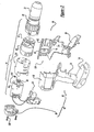
- Figure 1 is a side view of a power tool constructed in accordance with the teaching of the present invention.
- Figure 2 is an exploded perspective view of a portion of the power tool of Figure 1 ;
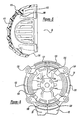
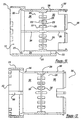
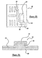
- Figure 3 is a perspective view of a portion of the housing of the power tool of Figure 1 illustrating the rear of the end cap assembly;
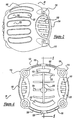
- Figure 4 is a front view of the end cap assembly
- Figure 5 is a section view taken along the line 5-5 of Figure 4 ;
- Figure 6 is a rear view of a portion of the power tool of Figure 1 with the end cap assembly removed;
- Figure 7 is a side view of a portion of the power tool of Figure 1 with the end cap assembly removed;
- Figure 8 is a view similar to that of Figure 4 , but illustrating the end cap shell prior to the overmolding operation;
- Figure 9 is a view similar to that of Figure 5 , but illustrating the end cap shell prior to the overmolding operation;
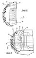
- Figure 10 is a view similar to that of Figure 4 , but illustrating an alternate construction of the overmold member
- Figure 11 is a partial sectional view of a portion of a power tool that employs an end cap assembly having an overmold member constructed in the manner illustrated in Figure 10 ;
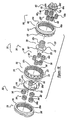
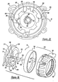
- Figure 12 is an exploded perspective view of a portion of the power tool of Figure 1 , illustrating the transmission assembly in greater detail;
- Figure 13 is an exploded perspective view of a portion of the power tool of Figure 1 , illustrating the reduction gearset assembly, the transmission sleeve, a portion of the housing and a portion of the clutch mechanism in greater detail;
- Figure 13a is a sectional view taken along a longitudinal axis of the second ring gear
- Figure 13b is a sectional view taken along a longitudinal axis of the third ring gear
- Figure 14 is a side view of the transmission sleeve
- Figure 15 is a rear view of the transmission sleeve
- Figure 16 is a sectional view taken along the line 16-16 of Figure 15 ;
- Figure 17 is a sectional view taken along the line 17-17 of Figure 15 ;
- Figure 18 is an exploded view of the reduction gearset assembly
- Figure 19 is a sectional view taken along a longitudinal axis of the power tool of Figure 1 illustrating a portion of the reduction gearset assembly in greater detail;
- Figure 20 is a front view of a portion of the first reduction carrier
- Figure 21 is a sectional view taken along a longitudinal axis of the power tool of Figure 1 illustrating a portion of the reduction gearset assembly in greater detail;
- Figure 22 is a rear view of a portion of the third reduction carrier
- Figure 23 is an sectional view taken along the longitudinal axis of the power tool of Figure 1 and illustrating the transmission assembly as positioned in the first speed ratio;
- Figure 24 is a sectional view similar to that of Figure 23 but illustrating the transmission assembly as positioned in the second speed ratio;
- Figure 25 is a sectional view similar to that of Figure 23 but illustrating the transmission assembly as positioned in the third speed ratio;
- Figure 26 is a top view of a portion of the power tool of Figure 1 illustrating the speed selector mechanism in greater detail;
- Figure 27a is a side view of the rotary selector cam
- Figure 27b is a top view of the rotary selector cam
- Figure 27c is a sectional view taken through along the central axis of the speed selector mechanism
- Figure 28 is a rear view of the output spindle assembly
- Figure 29 is an exploded perspective view of the clutch mechanism
- Figure 29a is a perspective view of a portion of the clutch mechanism illustrating another configuration of the clutch member
- Figure 29b is an exploded perspective view illustrating a multi-piece construction for the first ring gear and clutch member
- Figure 30 is a schematic illustration of the adjustment structure in an "unwrapped" state
- Figure 31 is a schematic illustration similar to that of Figure 30 but showing an alternate construction of the adjustment profile.
- Figure 32 is a schematic illustration similar to that of Figure 30 but showing a portion of another alternate construction of the adjustment profile
- a power tool constructed in accordance with the teachings of the present invention is generally indicated by reference numeral 10.
- the preferred embodiment of the present invention may be either a cord or cordless (battery operated) device, such as a portable screwdriver or drill.
- power tool 10 is a cordless drill having a housing 12, a motor assembly 14, a multi-speed transmission assembly 16, a clutch mechanism 18, an output spindle assembly 20, a chuck 22, a trigger assembly 24 and a battery pack 26.
- Those skilled in the art will understand that several of the components of power tool 10, such as the chuck 22, the trigger assembly 24 and the battery pack 26, are conventional in nature and need not be described in significant detail in this application. Reference may be made to a variety of publications for a more complete understanding of the operation of the conventional features of power tool 10.
- U.S. Patent No. 5,897,454 issued April 27, 1999 .
- Housing 12 includes an end cap assembly 30 and a handle shell assembly 32 that includes a pair of mating handle shells 34.
- Handle shell assembly 32 includes a handle portion 36 and a drive train or body portion 38.
- Trigger assembly 24 and battery pack 26 are mechanically coupled to handle portion 36 and electrically coupled to motor assembly 14.
- Body portion 38 includes a motor cavity 40 and a transmission cavity 42.
- Motor assembly 14 is housed in motor cavity 40 and includes a rotatable output shaft 44, which extends into transmission cavity 42.
- a motor pinion 46 having a plurality of gear teeth 48 is coupled for rotation with output shaft 44.
- Trigger assembly 24 and battery pack 26 cooperate to selectively provide electric power to motor assembly 14 in a manner that is generally well known in the art so as to control the speed and direction with which output shaft 44 rotates.
- Transmission assembly 16 is housed in transmission cavity 42 and includes a speed selector mechanism 60.
- Motor pinion 46 couples transmission assembly 16 to output shaft 44, transmitting a relatively high speed, low torque drive input to transmission assembly 16.
- Transmission assembly 16 includes a plurality of reduction elements that are selectively engaged by speed selector mechanism 60 to provide a plurality of speed ratios. Each of the speed ratios multiplies the speed and torque of the drive input in a predetermined manner, permitting the output speed and torque of the transmission assembly 16 to be varied in a desired manner between a relatively low speed, high torque output and a relatively high speed, low torque output.
- the transmission output is delivered the output spindle assembly 20, to which the chuck 22 is coupled for rotation, to permit torque to be transmitted to a tool bit (not shown).
- the clutch mechanism 18 is coupled to transmission assembly 16 and is operable for limiting the magnitude of the torque associated with the drive input to a predetermined, selectable torque limit.
- end cap assembly 30 is shown to include an end cap shell 100 and an overmold member 102.
- the end cap shell 100 is injection molded from a plastic material, such as ABS.
- the end cap shell 100 defines an end cap cavity 104 that is sized to receive the portion of the motor assembly 14 that extends rearwardly of the handle shell assembly 32.
- a plurality of first and second radial tab apertures 108 and 110 and the abutting face 128 are formed into the forward face 114 of the end cap shell 100 and a plurality of screw bosses 116 are formed into the perimeter of the end cap shell 100.
- Each of the first and second radial tab apertures 108 and 110 is sized to receive one of the first radial tabs 120 and second radial tabs 122, respectively, that are formed into the rearward face 124 of the handle shells 34.
- the first and second radial tab apertures 108 and 110 cooperate with the first and second radial tabs 122 to properly align the end cap shell 100 to the handle shell assembly 32, as well as to inhibit relative rotation therebetween.
- An arcuate portion 128 of the forward face 114 of the end cap shell 100 is angled to match the abutting face 132 of the rearward face 124 of the handle shells 34.
- the screw bosses 116 permit the end cap shell 100 to be fixedly coupled to the motor cover 136 via a plurality of screws 138.
- the geometry of the motor cover 136 is such that it is constrained to the handle shells 34. As such, fastening of the end cap shell 100 to the motor cover 136 operates to fixedly retain the end cap shell 100 against the rearward face 124 of the handle shell assembly 32, as well as to close off the rear handle aperture 139 in the handle shell assembly 32.
- a plurality of side apertures 140 are formed into the sides of the end cap shell 100 to permit air to flow through the handle shell assembly 32 and cool the motor assembly 14 in a manner that is well known in the art.
- a plurality of rear apertures 144 are formed into the rear of the end cap shell 100, with each of the rear apertures 144 including a recessed portion 146 that extends only partially into the outer surface 148 of the end cap shell 100 and a through-portion 150 that extends completely through the end cap shell 100.
- a pair of retaining tabs 152 are formed to extend from the interior surface 154 of the end cap shell 100 inwardly into the end cap cavity 104.
- a channel 156 is formed into the interior surface 154 of the end cap shell 100 and intersects each of the rear apertures 144 and the retaining tabs 152.
- the overmold member 102 is formed from a resilient material, such as thermoplastic elastomer (e.g., HYTREL® manufactured by E.I. du Pont de Nemours and Company) and is simultaneously formed and coupled to the end cap shell 100 in an injection molding operation.
- the overmold member 102 includes a plurality of bumper members 170, a pair of isolators 172 and a linking member 174.
- Each of the bumper members 170 extends from a point roughly coincident with the interior surface 154 of the end cap shell 100 to a point rearwardly of the outer surface 148 of the end cap shell 100 by about 0.5mm to about 1.5mm and preferably about 0.75mm.
- the bumper members 170 to provide a degree of shock absorption which reduces the likelihood of damaging the end cap shell 100 in the event that the tool 10 is dropped. Furthermore, it is sometimes necessary for an operator to apply a relatively high force to the tool 10, as when employing a hole saw to drill large diameter holes. In such situations, the operator is inclined to press onto the rear of the tool 10 to apply a force that is in-line with the axis of the chuck 22. In such situations, the bumper members 170 provide the operator with a relatively soft and comfortable surface which tends to resist slipping as well as attenuate the vibrations that are transmitted to the operator.
- the isolators 172 are formed about the retaining tabs 152 on the interior surface 154 of the end cap shell 100.
- each of the isolators 172 includes an annular member 180 that extends forwardly of the interior surface 154 of the end cap shell 100. Construction in this manner permits the end cap shell 100 to engage the isolators 172 to the outer diameter 14a and the rear surface 14b of the motor housing 14c to fixedly retain the motor 14d within the motor cover 136. This prevents the components of the motor assembly 14 from moving along the longitudinal axis of the tool 10, as well as dampens vibrations that are created during the operation of the motor assembly 14.
- the linking member 174 is fixedly coupled to each of the bumper members 170 and the isolators 172.
- the linking member 174 provides a flow path through which the resilient material flows during the formation of the bumper members 170 and the isolators 172.
- the linking member 174 also interconnects the bumper members 170 and the isolators 172, thereby rendering their removal from the end cap shell 100 more difficult.
- FIG. 10 and 11 One such example is illustrated in Figures 10 and 11 where the isolators 172 are modified to extend around the perimeter of a portion of the end cap cavity 104 and sealingly contact the rear surface 14b of the motor 14d.
- the isolators 172 seal the interface between the end cap shell 100 and the motor assembly 14, while the bumper members 170 seal the rear apertures 144 in the end cap shell 100.
- the space 188 defined by the isolators 172 is then filled with grease or another suitable lubricant, which lubricates a motor armature bearing 190.
- the transmission assembly 16 is shown to be a three-stage, three-speed transmission that includes a transmission sleeve 200, a reduction gearset assembly 202 and the speed selector mechanism 60.
- the transmission sleeve 200 includes a wall member 210 that defines a generally transmission bore or hollow cavity 212 into which the reduction gearset assembly 202 is disposed.
- the transmission sleeve 200 includes a body 214 and a base 216.
- the body 214 of the transmission sleeve 200 is fairly uniform in diameter and generally smaller in diameter than the base 216.
- the inside diameter of the base 216 is sized to receive the cylindrical nose portion 220 of the motor cover 136.
- a plurality of raised lands 226 are formed into the base 216.
- the raised lands 226 define a plurality of first grooves 228 in the outer surface 230 of the base 216 and a plurality of second grooves 232 in the inner surface 234 of the base 216.
- the first grooves 228 are configured to receive the alignment ribs 238 that are formed into the inner surface 242 of the handle shells 34 to align the transmission sleeve 200 to the handle shells 34 and inhibit relative rotation between the transmission sleeve 200 and the housing 12.
- the first grooves 228 and alignment ribs 238 are configured in a manner that the transmission sleeve 200 can only be assembled to the handle shells 34 in one orientation (i.e., the configuration of the first grooves 228 and alignment ribs 238 prevents the transmission sleeve 200 from being rotated 180° out of position relative to the handle shells 34).
- the second grooves 232 will be discussed in greater detail, below.
- the body 214 of the transmission sleeve 200 is shown to include a cylindrical body portion 246 and a pin housing portion 248.
- the cylindrical body portion 246 includes a selector cam guide 250, a plurality of lubricant grooves 252 and first and second sets of ring engagement teeth 254 and 256, respectively.
- the selector cam guide 250 is generally rectangular in cross section, extending outwardly from the top of the outer surface 258 of the body portion 246.
- the lubricant grooves 252 are formed concentrically around the upper half of the perimeter of the body portion 246.
- the lubricant grooves 252 have a depth of about 0.01 inch to about 0.030 inch to hold a lubricant, such as grease, on the upper half of the perimeter of the body portion 246.
- a lubricant such as grease
- a raised bead 264 segregates the interior of the body portion 246 into first and second housing portions 260 and 262, respectively.
- the first set of ring engagement teeth 254 are formed onto the inner surface 266 of the body portion 246 and extend rearwardly from the raised bead 264 toward the base 216.
- the second set of ring engagement teeth 256 are also formed into the inner surface of the body portion 246 but extend forwardly from the raised bead 264.
- the teeth 268 of the first and second sets of ring engagement teeth 254 and 256 are uniformly spaced around the inner surface 266 of the body portion 246.
- each tooth 268 in the first and second sets of ring engagement teeth 254 and 256 is similar in that each tooth extends from the raised bead 264, has a pair of parallel engagement surfaces 270 and terminates at a tip portion 272.
- the tip portion 272 of each tooth 268 is both rounded and tapered to enhance the ability with which it will mesh with a portion of the reduction gearset assembly 202 as will be described in detail, below.
- the pin housing portion 248 extends downwardly from the body portion 246 over a significant portion of the length of the body portion 246.
- An actuator aperture 274 is formed into the pin housing portion 248 and extends rearwardly through the base 216 of the transmission sleeve 200.
- the actuator aperture 274 is stepped, having a first portion 276 with a first diameter at the rear of the transmission sleeve 200 and a second portion 278 with a smaller second diameter at the front of the transmission sleeve 200.
- the first portion 276 of the actuator aperture 274 breaks through the wall of the first housing portion 260 and forms a groove 280 into the inner surface 234 of the base 216.
- the pin housing portion 248 will be discussed in further detail, below.
- a pair of first clip slots 284 and a pair of second clip slots 286 are formed into the transmission sleeve 200, extending along the sides of the transmission sleeve 200 in a manner that is parallel the longitudinal axis of the transmission sleeve 200.
- the first pair of clip slots 284 is formed through the sides of the body portion 246 rearwardly of the raised bead 264 and extends rearwardly toward the base 216.
- the depth of the first pair of clip slots 284 is such that they do not extend through the portion of the wall member 210 that defines the base 216.
- the second pair of clip slots 286 are also formed through the sides of the body portion 246 beginning forwardly of the raised bead 264 and extending through the front face 288 of the transmission sleeve 200.
- the reduction gearset assembly 202 includes a first reduction gear set 302, a second reduction gear set 304 and a third reduction gear set 306.
- the first, second and third reduction gear sets 302, 304 and 306 are operable in an active mode and an inactive mode. Operation in the active mode causes the reduction gear set to perform a speed reduction and torque multiplication operation, while operation of the reduction gear set in an inactive mode for causes the reduction gear set to provide an output having a speed and torque that is about equal to the speed and torque of the rotary input provided to that reduction gear set.
- each of the first, second and third reduction gear sets 302, 304 and 306 are planetary gear sets. Those skilled in the art will understand, however, that various other types of reduction gear sets that are well known in the art may be substituted for one or more of the reduction gear sets forming the reduction gearset assembly 202.
- the first reduction gear set 302 includes a first reduction element or ring gear 310, a first set of planet gears 312 and a first reduction carrier 314.
- the first ring gear 310 is an annular structure, having a plurality of gear teeth 310a formed along its interior diameter.
- a clutch face or profile 316 is formed into the outer perimeter of the front face 318 of the first ring gear 310 and will be discussed in greater detail, below.
- the first ring gear 310 is disposed within the portion of the hollow cavity 212 defined by the base 216; the front face 318 of the first ring gear 310 contacts a step 320 formed into the transmission sleeve 200, thereby limiting the ability of the first ring gear 310 to move forwardly into the hollow cavity 212.
- the first reduction carrier 314 is formed in the shape of a flat cylinder, having plurality of pins 322 that extend from its rearward face 324.
- a plurality of gear teeth 314a are formed into almost the entire outer perimeter of the first reduction carrier 314, with a valley 314b being formed between each pair of adjacent gear teeth 314a. Due to the spacing of the gear teeth 314a, one of the valleys (i.e., valley 314b') is relatively larger than the remaining valleys 314b due to the omission of a tooth 314a in the outer perimeter of the first reduction carrier 314.
- the gear teeth 314a of the first reduction carrier 314 are configured so as not to be meshingly engagable with the gear teeth 310a of the first ring gear 310.
- each gear tooth 314a terminates at a gradual radius 326 at the forward face 328 of the first reduction carrier 314 but terminates abruptly at the rearward face 324 of the first reduction carrier 314.
- a radius 330 is also formed on the valleys 314b between the gear teeth 314a.
- a first thrust washer 332 having a first annular portion 334, a second annular portion 336 and a plurality of retaining tabs 338 is positioned rearwardly of the first reduction gear set 302.
- the retaining tabs 338 engage the second grooves 232 in the base 216 of the transmission sleeve 200 and as such, relative rotation between the first thrust washer 332 and the transmission sleeve 200 is inhibited.
- the inside diameter of the base 216 is sized to receive the motor cover 136 and as such, the front face 340 of the motor cover 136 inhibits the axial movement of the first thrust washer 332.
- the first annular portion 334 contacts the rear face 342 of the first ring gear 310, providing a wear surface and controlling the amount by which the first ring gear 310 is able to move in an axial direction.
- the second annular portion 336 is spaced axially apart from the first annular portion 334, extending forwardly of the first annular portion 334 to provide a wear surface for the first set of planet gears 312 that also controls the amount by which they can move in an axial direction.
- the first set of planet gears 312 includes a plurality of planet gears 344, each of which being generally cylindrical in shape, having a plurality of gear teeth 344a formed into its outer perimeter and a pin aperture 346 formed its their center.
- Each planet gear 344 is rotatably supported on an associated one of the pins 322 and the first reduction carrier 314 and is positioned such that its teeth 344a meshingly engage the teeth 314a of the first ring gear 310.
- a raised portion 348 is formed into the front and rear face 350 and 352 of each planet gear 344 that inhibits the teeth 344a from rubbing on the first reduction carrier 314 and the first thrust washer 332 and creating dust or chips that would impair the performance of the transmission assembly 16 and reduce its operating life.
- the motor pinion 46 serves as a sun gear for the first reduction gear set 302.
- the second reduction gear set 304 is disposed within the portion of the hollow cavity 212 defined by the first housing portion 260 and includes a second sun gear 358, a second reduction element or ring gear 360, a second set of planet gears 362 and a second reduction carrier 364.
- the second sun gear 358 is fixed for rotation with the first reduction carrier 314.
- the second sun gear 358 includes a plurality of gear teeth 358a that extend forwardly of the forward face 328 of the first reduction carrier 314.
- the second ring gear 360 is an annular structure, having a plurality of gear teeth 360a formed along its interior diameter.
- the gear teeth 360a may be heavily chamfered at the rear face 366 of the second ring gear 360 but terminate abruptly at the front face 368. More preferably, a heavy radius 369 is formed onto the rear face 366 and the sides of each of the gear teeth 360a, with the heavy radius 369 being employed rather than the heavy chamfer as the heavy radius 369 on the gear teeth 360a provides for better engagement between the second ring gear 360 and the first reduction carrier 314.
- a plurality of sleeve engagement teeth 370 are formed into the outer perimeter of the second ring gear 360; the sleeve engagement teeth 370 extend forwardly toward the front face 368 of the second ring gear 360 and terminate at a tip portion 372 that is rounded and tapers forwardly and inwardly.
- An annular clip groove 374 is also formed into the outer perimeter of the second ring gear 360.
- the clip groove 374 is a rectangular slot having a pair of sidewalls 376. The clip groove 374 will be discussed in greater detail, below.
- the second reduction carrier 364 is formed in the shape of a flat cylinder, having plurality of pins 378 that extend from its rearward face 380.
- the second set of planet gears 362 is shown to include a plurality of planet gears 382.
- Each planet gear 382 is generally cylindrical in shape, having a plurality of gear teeth 382a formed into its outer perimeter and a pin aperture 384 formed its center.
- Each planet gear 382 is rotatably supported on an associated one of the pins 378 and the second reduction carrier 364 is positioned such that the gear teeth 382a of the planet gears 382 meshingly engage the gear teeth 360a of the second ring gear 360.
- the gear teeth 358a of the second sun gear 358 are also meshingly engaged with the gear teeth 382a of the planet gears 382.
- the third reduction gear set 306 is disposed within the portion of the hollow cavity 212 defined by the second housing portion 262 and includes a third sun gear 398, a third reduction element or ring gear 400, a third set of planet gears 402 and a third reduction carrier 404.
- the third sun gear 398 is fixed for rotation with the second reduction carrier 364.
- the third sun gear 398 includes a plurality of gear teeth 398a that extend forwardly of the front face 406 of the second reduction carrier 364.
- the third ring gear 400 is an annular structure, having a plurality of gear teeth 400a formed along its interior diameter.
- the gear teeth 400a may be heavily chamfered at the front face 412 of the third ring gear 400, but terminate abruptly at the rear face 414.
- a heavy radius 407 is formed onto the front face 412 and the sides of each of the gear teeth 400a, with the heavy radius 407 being employed rather than the heavy chamfer as the heavy radius 407 on the gear teeth 400a provides for better engagement between the third ring gear 400 and the third reduction carrier 404.
- a plurality of sleeve engagement teeth 418 are formed into the outer perimeter of the third ring gear 400; the sleeve engagement teeth 418 extend rearward toward the rear face 414 of the third ring gear 400 and terminate at a tip portion 420 that is rounded and tapers rearwardly and inwardly.
- An annular clip groove 422 is also formed into the outer perimeter of the third ring gear 400.
- the clip groove 422 is a rectangular slot having a pair of sidewalls 424. The clip groove 422 will be discussed in greater detail, below.
- the third reduction carrier 404 is formed in the shape of a flat cylinder, having plurality of pins 428 that extend from its rearward face 430.
- a plurality of gear teeth 404a are formed into almost the entire outer perimeter of the third reduction carrier 404, with a valley 404b being formed between each pair of adjacent teeth 404a. Due to the spacing of the teeth 404a, one of the valleys 404b (i.e., valley 404b') is relatively larger than the remaining valleys 404b due to the omission of a tooth 404a in the outer perimeter of the third reduction carrier 404.
- the gear teeth 404a of the third reduction carrier 404 are configured so as not to be meshingly engagable with the gear teeth 382a of the second planet gears 382.
- the profile of the gear teeth 404a is illustrated in greater detail. As shown, the rear face 430 of the third reduction carrier 404 is chamfered and a heavy radius 434 is formed into each of sides of the teeth 404a and valleys 404b. Each gear tooth 404a terminates abruptly at the forward face 436 of the third reduction carrier 404.
- the third set of planet gears 402 is shown to include a plurality of planet gears 438.
- Each planet gear 438 is generally cylindrical in shape, having a plurality of gear teeth 438a formed into its outer perimeter and a pin aperture 440 formed through its center.
- Each planet gear 438 is rotatably supported on an associated one of the pins 428 and the third reduction carrier 404 is positioned such that the gear teeth 438a of the planet gears 438 meshingly engage the gear teeth 400a of the third ring gear 400.
- a raised portion 442 is formed into each of the front and rear faces of the planet gears 438 which inhibits the gear teeth 438a from rubbing on the third reduction carrier 404 and creating dust or chips that would impair the performance of the transmission assembly 12 and reduce its operating life.
- a second thrust washer 450 is disposed around the third sun gear 398 and the teeth 398a of the third sun gear 398 are meshingly engaged with the gear teeth 438a of the planet gears 438.
- the second thrust washer 450 includes a plurality of retaining tabs 452 that are configured to engage corresponding tab grooves 454 ( Figure 13 ) that are formed in the inner surface 266 of body portion 246 of the transmission sleeve 200. The retaining tabs 452 and the tab grooves 454 cooperate to inhibit relative rotation between the second thrust washer 450 and the transmission sleeve 200.
- the output spindle assembly 20 includes a transmitting means 458 for coupling a spindle 460 for rotation with the third reduction carrier 404 so as to transmit drive torque from the reduction gearset assembly 202 to the chuck 22.
- a transmitting means 458 are well known in the art and easily adapted to the transmission assembly of a power tool of the present invention. Accordingly, a detailed discussion of the transmitting means 458 need not be included herein.
- the speed selector mechanism 60 is movable between a first position 500, a second position 502 and a third position 504 and includes a switch portion 510 for receiving a speed change input and an actuator portion 512 for manipulating the reduction gearset assembly 202 in accordance with the speed change input.
- the actuator portion 512 is operatively coupled to the reduction gearset assembly 202 and moves the second and third reduction gear sets 304 and 306 between the active and inactive modes in response to movement of the switch portion 510 between the first, second and third positions 500, 502 and 504.
- the actuator portion 512 includes a rotary selector cam 520, a plurality of wire clips 522 and a spring member 523.
- Each of the wire clips 522 is formed from a round wire which is bent in the shape of a semi-circle 524 with a pair of tabs 526 extending outwardly from the semi-circle 524 and positioned on about the centerline of the semi-circle 524.
- the semi-circle 524 is sized to fit within the clip grooves 374 and 422 in the second and third ring gears 360 and 400, respectively.
- the semi-circle 524 neither extends radially outwardly of an associated one of the ring gears (360, 400), nor binds against the sidewalls (376, 424) of the clip grooves (374, 422).
- the sidewalls (376, 424) of the clip grooves (374, 422) are spaced apart about 0.05 inch and the diameter of the wire forming the wire clips 522 is about 0.04 inch.
- the tabs 526 of the wire clips 522 extend outwardly of the hollow cavity 212 into an associated one of the clip slots (284, 286) that is formed into the transmission sleeve 200.
- the tabs 526 are long enough so that they extend outwardly of the outer surface 258 of the body 214 of the transmission sleeve 200, but not so far as to extend radially outwardly of the portion of the first clip slots 284 in the base 216 of the transmission sleeve 200.
- Configuration of the wire clips 522 in this manner facilitates the assembly of the transmission assembly 16, permitting the wire clips 522 to be installed to the second and third ring gears 360 and 400, after which these assemblies are inserted into the hollow cavity 212 along the longitudinal axis of the transmission sleeve 200.
- the rotary selector cam 520 is illustrated to include an arcuate selector body 530, a switch tab 532 and a plurality of spacing members 534.
- a pair of first cam slots 540a and 540b, a pair of second cam slots 544a and 544b, a spring aperture 546 and a guide aperture 548 are formed through the selector body 530.
- the selector body 530 is sized to engage the outside diameter of the body portion 246 of the transmission sleeve 200 in a slip-fit manner.
- the guide aperture 548 is generally rectangular in shape and sized to engage the front and rear surfaces of the selector cam guide 250.
- the guide aperture 548 is considerably wider than the width of the selector cam guide 250, being sized in this manner to permit the rotary selector cam 520 to be rotated on the transmission sleeve 200 between a first rotational position, a second rotational position and a third rotational position.
- the selector cam guide 250 and cooperates with the guide aperture 548 to limit the amount by which the rotary selector cam 520 can be rotated on the transmission sleeve 200, with a first lateral side of the selector cam guide 250 contacting a first lateral side of the guide aperture 548 when the rotary selector cam 520 is positioned in the first rotational position, and a second lateral side of the selector cam guide 250 contacting a second lateral side of the guide aperture 548 when the rotary selector cam 520 is positioned in the third rotational position.
- first cam slot 540a includes a first segment 550, a second segment 552 and an intermediate segment 554.
- the first segment 550 is located a first predetermined distance away from a reference plane 558 that is perpendicular to the longitudinal axis of the rotary selector cam 520 and the second segment 552 is located a second distance away from the reference plane 558.
- the intermediate segment 554 couples the first and second segments 550 and 552 to one another.
- first cam slot 540b is identical to that of first cam slot 540a, except that it is rotated relative to the rotary selector cam 520 such that each of the first, second and intermediate segments 550, 552 and 554 in the first cam slot 540b are located 180° apart from the first, second and intermediate segments 550, 552 and 554 in the first cam slot 540a.
- second cam slot 544a is sized to receive one of the tabs 526 of a corresponding one of the wire clips 522.
- second cam slot 544a includes a first segment 560, a second segment 562, a third segment 564 and a pair of intermediate segments 566 and 568.
- the first and third segments 560 and 564 are located a third predetermined distance away from the reference plane and the second segment 562 is located a fourth distance away from the reference plane 558.
- the intermediate segment 566a couples the first and second segments 560 and 562 to one another and the intermediate segment 568 couples the second and third segments 562 and 566 together.
- second cam slot 544b is identical to that of second cam slot 544a, except that it is rotated relative to the rotary selector cam 520 such that each of the first, second, third and intermediate segments 560, 562, 564 and 566 and 568 in the second cam slot 544b are located 180° apart from the first, second, third and intermediate segments 560, 562, 564 and 566 and 568 in the second cam slot 544a.
- the rotary selector cam 520 may be rotated on the transmission sleeve 200 between the first, second and third positions 500, 502 and 504 to selectively engage and disengage the second and third ring gears 360 and 400 from the first and third reduction carriers 314 and 404, respectively.
- the first cam slots 540a and 540b and the second cam slots 544a and 544b confine the wire tabs 526 of their associated wire clip 522 and cause the wire tabs 526 to travel along the longitudinal axis of the transmission sleeve 200 in an associated one of the first and second clip slots 284 and 286. Accordingly, the rotary selector cam 520 is operative for converting a rotational input to an axial output that causes the wire clips 522 to move axially in a predetermined manner.
- a lubricant (not specifically shown) is applied to the lubricant grooves 252 formed into body portion 246 of the transmission sleeve 200 is employed to lubricate the interface between the transmission sleeve 200 and the rotary selector cam 520.
- Positioning the rotary selector cam 520 in the first rotational position 500 causes the tabs 526 of the wire clip 522 that is engaged to the second ring gear 360 to be positioned in the first segment 550 of the first cam slots 540a and 540b and the tabs 526 of the wire clip 522 that is engaged to the third ring gear 400 to be positioned in the first segment 560 of the second cam slots 544a and 544b. Accordingly, positioning of the rotary selector cam 520 in the first rotational position causes the second and third ring gears 360 and 400 to be positioned in meshing engagement with the second and third planet gears 362 and 402, respectively.
- the sleeve engagement teeth 370 and 418 of the second and third ring gears 360 and 400 are positioned in meshing engagement with the first and second sets of ring engagement teeth 254 and 256, respectively, to inhibit relative rotation between the second and third ring gears 360 and 400 and the transmission sleeve 200 to thereby providing the transmission assembly 16 with a first overall gear reduction or speed ratio 570 as shown in Figure 23 .
- tip portion 272 of the teeth 268 of the first and second sets of ring engagement teeth 254 and 256 and the tip portions 372 and 420 of the sleeve engagement teeth 370 and 418, respectively, are rounded and tapered so as to improve their capability for meshing engagement in response to axial repositioning along a longitudinal axis of the transmission assembly 16.
- Positioning the rotary selector cam 520 in the second rotational position 502 causes the tabs 526 of the wire clip 522 that is engaged to the second ring gear 360 to be positioned in the first segment 550 of the first cam slots 540a and 540b and the tabs 526 of the wire clip 522 that is engaged to the third ring gear 400 to be positioned in the second segment 562 of the second cam slots 544a and 544b. Accordingly, positioning of the rotary selector cam 520 in second rotational position causes the second ring gear 360 to be in meshing engagement with the second planet gears 362 and the third ring gear 400 in meshing engagement with both the third planet gears 402 and the third reduction carrier 404.
- Positioning of the rotary selector cam 520 in the second rotational position 502 also positions the sleeve engagement teeth 370 of the second ring gear 360 in meshing engagement with the first set of ring engagement teeth 254 while the sleeve engagement teeth 418 of the third ring gear 400 are not meshingly engaged with the second set of ring engagement teeth 256.
- relative rotation between the second ring gear 360 and the transmission sleeve 200 is inhibited, while relative rotation between the third ring gear 400 and the transmission sleeve 200 is permitted to thereby provide the transmission assembly 16 with a second overall gear reduction or speed ratio 572 as illustrated in Figure 24 .
- Positioning the rotary selector cam 520 in the third rotational position 504 causes the tabs 526 of the wire clip 522 that is engaged to the second ring gear 360 to be positioned in the second segment 552 of the first cam slots 540a and 540b and the tabs 526 of the wire clip 522 that is engaged to the third ring gear 400 to be positioned in the third segment 564 of the second cam slots 544a and 544b. Accordingly, positioning of the rotary selector cam 520 in the third rotational position causes the second ring gear 360 to be in meshing engagement with both the second planet gears 362 and the first reduction carrier 314 while the third ring gear 400 in meshing engagement with only the third planet gears 402.
- Positioning the rotary selector cam 520 in the third rotation position 504 also positions the sleeve engagement teeth 370 on the second ring gear 360 out of meshing engagement with the first set of ring engagement teeth 254 and the sleeve engagement teeth 418 on the third ring gear 400 in meshing engagement with the second sets of ring engagement teeth 256 to inhibit relative rotation between the second ring gear 360 and the transmission sleeve 200 and permit relative rotation between the third ring gear 400 and the transmission sleeve 200 to provide the transmission assembly 16 with a third overall gear reduction or speed ratio 574.
- the spring member 523 is formed from a flat rectangular piece of spring steel and includes a flattened Z-shaped portion 580 and a raised portion 584.
- the flattened Z-shaped portion 580 is configured to wrap around two reinforcement bars 586 that extend into the spring aperture 546, thereby permitting the raised portion 584 to be maintained at a predetermined position and also to transmit a spring force between the rotary selector cam 520 and the spring member 523.
- the raised portion 584 of the spring member 523 is sized to engage internal notches 590 formed in the housing 592 of the output spindle assembly 20.
- Lands 594 that are circumferentially spaced from the rotary selector cam 520 are formed between the notches 590.
- the raised portion 584 of the spring member 523 engages an associated one of the notches 590.
- the force that is generated by the spring member 523 when the raised portion 584 is moved downwardly toward the rotary selector cam 520 in response to contact between the raised portion 584 and the land 594 acts to inhibit unintended rotation of the speed selector mechanism 60.
- placement of the raised portion 584 in a notch 590 provides the user with a tactile indication of the positioning of the rotary selector cam 520.
- switch portion 510 is shown to include an arcuate band 600 having a raised hollow and rectangular selector button 602 formed therein.
- the arcuate band 600 is formed from a plastic material and is configured to conform to the outer diameter of the rotary selector cam 520.
- the open end of the selector button 602 is configured to receive the switch tab 532, thereby permitting the switch portion 510 and the rotary selector cam 520 to be coupled to one another in a fastenerless manner.
- the plurality of spacing members 534 are raised portions formed into the rotary selector cam 520 that are concentric to and extend radially outwardly from the selector body 530.
- the spacing members 534 elevate the arcuate band 600 to prevent the arcuate band from contacting the wire tabs 526 in the first cam slots 540a and 540b.
- the spacing members 534 may also be employed to selectively strengthen areas of the rotary selector cam 520, such as in the areas adjacent the first cam slots 540a and 540b.
- the rotary selector cam 520 i.e., the first cam slots 540a and 540b and the second cam slots 544a and 544b
- the second ring gear 360 meshingly engages both the second planet gears 362 and the first reduction carrier 314 while the third ring gear 400 meshingly engages both the third planet gears 402 and the third reduction carrier 404 to thereby providing the transmission assembly 16 with a fourth overall gear reduction or speed ratio.
- selector mechanisms of other configurations may be substituted for the selector mechanism 60 illustrated herein.
- These selector mechanisms may include actuators that are actuated via rotary or sliding motion and may include linkages, cams or other devices that are well known in the art to slide the second and third ring gears 360 and 400 relative to the transmission sleeve 200.
- the switch mechanism 60 could also be configured to position the second and third ring gears 360 and 400 independently of one another.
- the clutch mechanism 18 is shown to include a clutch member 700, an engagement assembly 702 and an adjustment mechanism 704.
- the clutch member 700 is shown to be an annular structure that is fixed to the outer diameter of the first ring gear 310 and which extends radially outwardly therefrom.
- the clutch member 700 includes an arcuate clutch face or profile 316 that is formed into the front face 318 of the first ring gear 310.
- the outer diameter of the clutch member 700 is sized to rotate within the portion of the hollow cavity 212 that is defined by the base 216 of the transmission sleeve 200.
- the clutch face or profile 316 of the example illustrated is shown to be defined by a plurality of peaks 710 and valleys 712 that are arranged relative to one another to form a series of ramps that are defined by an angle of about 18°.
- peaks 710 and valleys 712 that are arranged relative to one another to form a series of ramps that are defined by an angle of about 18°.
- other clutch face or profile configurations may also be employed, such as a sinusoidally shaped clutch face or profile 316' ( Figure 29a ).
- first ring gear 310 and the clutch member 700 have been illustrated as a one piece (i.e., unitarily formed) construction, those skilled in the art will understand that they may be constructed otherwise.
- One such embodiment is illustrated in Figure 29b wherein the first ring gear 310' is shown to include an annular collar 1000 and a plurality of tab apertures 1002.
- the annular collar 1000 is illustrated to include a plurality of ramps 1004 that have dual sloping sides, but is otherwise flat.
- the first ring gear 310' is otherwise identical to the first ring gear 310.
- An annular damper 1008 abuts the annular collar 1000 and includes a plurality of tab members 1010 that engage the tab apertures 1002 in the first ring gear 310' to prevent the damper 1008 from rotating relative to the first ring gear 310'.
- the damper 1008 includes a body portion 1012 that is configured to match the contour of the annular collar 1000 and as such, includes a plurality of mating ramped portions 1014 that are configured to engage each of the ramps 1004.
- the damper 1008 is formed from a suitable impact dampening material, such as acetyl.
- the clutch member 700' which is an annular member that is formed from a wear resistant material, such as hardened 8620 steel, is disposed over the damper 1008.
- the clutch member 700' includes a plurality of tab members 1020, which lock into the tab apertures 1002 to prevent rotation relative to the first ring gear 310', and a plurality of mating ramped portions 1022.
- the mating ramped portions 1022 of the clutch member 700' matingly engage the mating ramped portions 1014 of the damper 1008. While the construction in this manner is more expensive relative to the previously described embodiment, it is more tolerant of high impact forces that are associated with the operation of the clutch mechanism 18.
- the engagement assembly 702 includes a pin member 720, a follower spring 722 and a follower 724.
- the pin member 720 includes a cylindrical body portion 730 having an outer diameter that is sized to slip-fit within the second portion 278 of the actuator aperture 274 that is formed into the pin housing portion 248 of the transmission sleeve 200.
- the pin member 720 also includes a tip portion 732 and a head portion 734.
- the tip portion 732 is configured to engage the adjustment mechanism 704 and in the example shown, is formed into the end of the body portion 730 of the pin member 720 and defined by a spherical radius.
- the head portion 734 is coupled to the end of the body portion 730 opposite the tip portion 732 and is shaped in the form of a flat cylinder or barrel that is sized to slip fit within the first portion 276 of the actuator aperture 274. Accordingly, the head portion 734 prevents the pin member 720 from being urged forwardly out of the actuator aperture 274.
- the follower spring 722 is a compression spring whose outside diameter is sized to slip fit within the first portion 276 of the actuator aperture 274.
- the forward end of the follower spring 722 contacts the head portion 734 of the pin member 720, while the opposite end of the follower spring 722 contacts the follower 724.
- the end portion 740 of the follower 724 is cylindrical in shape and sized to slip fit within the inside diameter of the follower spring 722.
- the end portion 740 of the follower acts as a spring follower to prevent the follower spring 722 from bending over when it is compressed.
- the follower 724 also includes a follower portion 744 having a cylindrically shaped body portion 746, a tip portion 748 and a flange portion 750.
- the body portion 746 is sized to slip fit within the first portion 276 of the actuator aperture 274.
- the tip portion 748 is configured to engage the clutch face 316 and in the example shown, is formed into the end of the body portion 746 of the follower 724 and defined by a spherical radius.
- the flange portion 750 is formed at the intersection between the body portion 746 and the end portion 740.
- the flange portion 750 is generally flat and configured to receive a biasing force that is exerted by the follower spring 722.
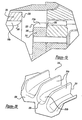
- the adjustment mechanism 704 is also shown to include an adjustment structure 760 and a setting collar 762.
- the adjustment structure 760 is shaped in the form of a generally hollow cylinder that is sized to fit a housing portion 766 of the output spindle assembly 20.
- the adjustment structure 760 includes an annular face 768 into which an adjustment profile 770 is formed.
- the adjustment profile 770 includes a first adjustment segment 772, a last adjustment segment 774, a plurality of intermediate adjustment segments 776 and a ramp section 778 between the first and last adjustment segments 772 and 774.
- a second ramp section 779 is included between the last intermediate adjustment segment 776z and the last adjustment segment 774.
- the portion of the adjustment profile 770 from the first adjustment segment 772 through the last one of the intermediate adjustment segments 776z is formed as a ramp having a constant slope. Accordingly, a follower 780 that is coupled to the housing portion 766 of the output spindle assembly 20 is biased radially outwardly toward the inside diameter of the adjustment structure 760 where it acts against the plurality of detents 782 that are formed into the adjustment mechanism 704 (e.g., in the setting collar 762).
- the follower 724 and plurality of detents 782 cooperate to provide the user of tool 10 with a tactile indication of the position of the adjustment profile 770 as well as inhibit the free rotation of the adjustment structure 760 so as to maintain the position of the adjustment profile 770 at a desired one of the adjustment segments 772, 774 and 776.
- the setting collar 762 is coupled to the exterior of the adjustment structure 760 and includes a plurality of raised gripping surfaces 790 that permit the user of the tool 10 to comfortably rotate both the setting collar 762 and the adjustment structure 760 to set the adjustment profile 770 at a desired one of the adjustment segments 772, 774 and 776.
- a setting indicator 792 is employed to indicate the position of the adjustment profile 770 relative to the housing portion 766 of the output spindle assembly 20.
- the setting indicator 792 includes an arrow 794 formed into the housing portion 766 of the output spindle assembly 20 and a scale 796 that is marked into the circumference of the setting collar 762.
- an initial drive torque is transmitted by the motor pinion 46 from the motor assembly 14 to the first set of planet gears 312 causing the first set of planet gears 312 to rotate.
- a first intermediate torque is applied against the first ring gear 310. Resisting this torque is a clutch torque that is applied by the clutch mechanism 18.
- the clutch torque inhibits the free rotation of the first ring gear 310, causing the first intermediate torque to be applied to the first reduction carrier 314 and the remainder of the reduction gearset assembly 202 so as to multiply the first intermediate torque in a predetermined manner according to the setting of the switch mechanism 60.
- the clutch mechanism 18 biases the first reduction gearset 302 in the active mode.
- the magnitude of the clutch torque is dictated by the adjustment mechanism 704, and more specifically, the relative height of the adjustment segment 772, 774 or 776 that is in contact with the tip portion 732 of the pin member 720. Positioning of the adjustment mechanism 704 at a predetermined one of the adjustment segments 772, 774 or 776 pushes the pin member 720 rearwardly in the actuator aperture 274, thereby compressing the follower spring 722 and producing the a clutch force. The clutch force is transmitted to the flange portion 750 of the follower 724, causing the tip portion 748 of the follower 724 to engage the clutch face or profile 316 and generating the clutch torque.
- Positioning of the tip portion 748 of the follower 724 in one of the valleys 712 in the clutch face or profile 316 operates to inhibit rotation of the first ring gear 310 relative to the transmission sleeve 200 when the magnitude of the clutch torque exceeds the first intermediate torque.
- the first ring gear 310 is permitted to rotate relative to the transmission sleeve 200.
- rotation of the first ring gear 310 may cause the clutch force to increase a sufficient amount to resist further rotation.
- the first ring gear 310 will rotate in an opposite direction when the magnitude of the first intermediate torque diminishes, permitting the tip portion 748 of the follower 724 to align in one of the valleys 712 in the clutch face or profile 316. If rotation of the first ring gear 310 does not cause the clutch force to increase sufficiently so as to fully resist rotation of the first ring gear 310, the first reduction gearset 302 will be placed in the inactive mode wherein the first ring gear 310 will rotate so as to inhibit the transmission of the first intermediate torque to the first reduction carrier 314. In such situations, no torque will be transmitted through the portions of the transmission assembly 16 that are located forwardly of the first set of planet gears 312 (e.g., the first reduction carrier 314, the second sun gear 358, the second set of planet gears 362).
- the first set of planet gears 312 e.g., the first reduction carrier 314, the second sun gear 358, the second set of planet gears 362).
- Configuration of the clutch mechanism 18 in this manner is highly advantageous in that the clutch torque is sized to resist the first intermediate torque, as opposed to the output torque of the tool 10 that is generated by the multi-reduction transmission assembly 16 and transmitted through the chuck 22.
- the clutch mechanism 18 may be sized in a relatively small manner, thereby improving the ability with which it can be incorporated or packaged into the tool 10.
- the clutch mechanism 18 is operable over a relatively large span of output torques.
- the clutch mechanism 18 of the power tool of the present invention can accommodate a considerable shift in the magnitude of the output torque of the tool 10 by simply operating the transmission assembly 16 in a different (i.e., lower or higher) gear ratio.
- the adjustment mechanism 704 may be rotated relative to the output spindle assembly 20 to position the adjustment mechanism 704 at a desired one of the adjustment segments 772, 774 and 776 to perform the first operation and thereafter rotated to a second one of the adjustment segments 772, 774 and 776 to perform the second operation.
- the adjustment mechanism 704 is configured such that the adjustment structure 760 and the setting collar 762 are rotatable through an angle of 360°.
- the adjustment structure 760 Assuming the adjustment structure 760 to be positioned at an intermediate adjustment segment 776x, rotation of the adjustment mechanism 704 through an angle of 360° would rotate the adjustment structure 760 past the other intermediate adjustment segments 776, as well as the first and last adjustment segments 772 and 774 and the ramp section 778 such that the adjustment structure 760 would again be positioned at the intermediate adjustment segment 776x.
- the feature is especially convenient when it is necessary to change the clutch setting between a relatively high clutch setting and a relatively low clutch setting.
- the ramp section 778 permits the setting collar 762 (and adjustment structure 760) to be rotated from highest clutch setting, corresponding to the last adjustment segment, to the lowest clutch setting, corresponding to the first clutch setting, without positioning the clutch mechanism 18 in one of the intermediate clutch settings. Accordingly, the user of the tool 10 is able to vary the clutch setting from its maximum setting to its minimum setting (and vice versa) by rotating the setting collar 762 a relatively small amount.
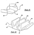
- the adjustement profile 770 may be constructed somewhat differently.
- the adjustment profile 770' may be formed such that each of the first, last and intermediate adjustment segments 772', 774' and 776' is detented as illustrated in Figure 31 .
- the detents 782 in the adjustment structure 760 and the follower 780 in the housing portion 766 of the output spindle assembly 20 are unnecessary as the adjustment segments 772', 774' and 776' will cooperate with the engagement 702 to provide the user of the tool 10 with a tactile indication of the position of the adjustment profile 770', as well as inhibit the free rotation of the adjustment structure 760.
- FIG. 32 Another example is illustrated in Figure 32 wherein the adjustment profile 770" is generally similar to the adjustment profile 770 except that the ramp section 779 has been omitted so that the last intermediate adjustment segment 776z is immediately adjacent the last adjustment segment 774.
Abstract
Description
- The present invention relates generally to power tools such as rotatable drills and power screwdrivers. More particularly, the present invention relates to a power tool according to the preamble of
claim 1. Such a tool is known fromUS 6 076 438 . - Modernly, manufacturers of power tools have introduced rotary power tools that have variable speed motors in an attempt to provide the users of these tools with sufficient control over the output speed of the tool so as to permit them to perform diverse operations without resort to additional, specialized tools. Many of the tools that are commercially available include a three-stage, two-speed transmission that permits even greater control over speeds of these tools.
- Typically, the known transmission arrangements have lacked a configuration that could produce a wide range of output speeds and torques that would permit the tool to perform diverse operations such as drilling holes with a large diameter hole saw, installing drywall screws or large diameter lag screws, and performing highspeed drilling operations. The single or dual speed transmissions that were generally employed in these tools typically did not have sufficient speed reducing capacity to permit these transmissions to be diversely employed as configuring these tools for high torque operations tended to impair their high speed performance. Furthermore, the rechargeable batteries that were employed in many of the early cordless rotary power tools were not well suited for use in low-speed, high torque operations due to the amount of energy that is consumed and the rate with which the energy is consumed by the power tool during such operations. Consequently, consumers were often forced to purchase two different rotary power tools, a medium-duty tool for "standard" applications such as drilling and fastening, and a heavy-duty tool having a low-speed, high torque output for more demanding tasks.
- With the advent of the modern high capacity, high voltage battery, it is now possible to meet the energy demands of a power tool that is used in low-speed, high torque operations. There remains, however, a need in the art for a clutch arrangement which can be used throughout a relatively large speed reducing range.
- Typical clutch arrangements permit the user of the tool to limit the torque that is output by the last stage of the tool's transmission. These clutch arrangements commonly employ a spring that biases two portions of the clutch into engagement. When the torque that is output by the transmission exceeds the predetermined clutch setting, the biasing force exerted by the spring is not sufficient to maintain the portion of the clutch in an engaged condition and as such, one of the portions of the clutch is able to rotate relative to the other portion of the clutch. The relative movement of these two portions effectively inhibits the transmission of torque to the output shaft of the tool.
- The use of such clutch arrangements with a transmission having a relatively large speed reducing range is often times impractical for the simple reason that the biasing force that is exerted by the spring does not have sufficient range to permit the clutch portions to be properly engaged and disengaged over the entire speed reducing range. Accordingly, it is relatively common to supply several different sized springs with a clutch arrangement, necessitating that the user select and install an appropriately sized spring for a given task. While this approach has been effective, it is nonetheless time consuming and inconvenient.
- Accordingly there is provided a power tool comprising:
- a motor having an output shaft;
- a transmission having a first portion with a first gear ratio and a second portion having an output gear ratio, the first portion including a planetary gear assembly with a ring gear, a sun gear and a planet gear assembly, the ring gear not being shared with the second portion of the transmission, the planet gear assembly having a planet carrier and a plurality of planet gears, the planet carrier having a plurality of pins for rotatably supporting the plurality of planet gears and an output sun gear, the plurality of planet gears meshingly engaged with the sun gear and the ring gear, the sun gear coupled to the output shaft and receiving a torque input from the motor, the output sun gear meshingly engaged with the second portion and outputting an intermediate torque output, the second portion receiving the intermediate torque output and producing an output torque; and
- a clutch assembly for limiting a torque output of the power tool, the clutch assembly having an annular clutch member and an engagement assembly, the clutch member coupled to the ring gear, the clutch member having a predetermined clutch profile and the engagement assembly having a follower member, the follower member abutting the clutch member and cooperating with the clutch profile to inhibit relative rotation between the clutch member and the follower member only when the magnitude of the intermediate torque output is less than a predetermined maximum torque.
- Additional advantages and features of the present invention will become apparent from the subsequent description and the appended claims, taken in conjunction with the accompanying drawings, wherein:
-
Figure 1 is a side view of a power tool constructed in accordance with the teaching of the present invention; -
Figure 2 is an exploded perspective view of a portion of the power tool ofFigure 1 ; -
Figure 3 is a perspective view of a portion of the housing of the power tool ofFigure 1 illustrating the rear of the end cap assembly; -
Figure 4 is a front view of the end cap assembly; -
Figure 5 is a section view taken along the line 5-5 ofFigure 4 ; -
Figure 6 is a rear view of a portion of the power tool ofFigure 1 with the end cap assembly removed; -
Figure 7 is a side view of a portion of the power tool ofFigure 1 with the end cap assembly removed; -
Figure 8 is a view similar to that ofFigure 4 , but illustrating the end cap shell prior to the overmolding operation; -
Figure 9 is a view similar to that ofFigure 5 , but illustrating the end cap shell prior to the overmolding operation; -
Figure 10 is a view similar to that ofFigure 4 , but illustrating an alternate construction of the overmold member; -
Figure 11 is a partial sectional view of a portion of a power tool that employs an end cap assembly having an overmold member constructed in the manner illustrated inFigure 10 ; -
Figure 12 is an exploded perspective view of a portion of the power tool ofFigure 1 , illustrating the transmission assembly in greater detail; -
Figure 13 is an exploded perspective view of a portion of the power tool ofFigure 1 , illustrating the reduction gearset assembly, the transmission sleeve, a portion of the housing and a portion of the clutch mechanism in greater detail; -
Figure 13a is a sectional view taken along a longitudinal axis of the second ring gear; -
Figure 13b is a sectional view taken along a longitudinal axis of the third ring gear; -
Figure 14 is a side view of the transmission sleeve; -
Figure 15 is a rear view of the transmission sleeve; -
Figure 16 is a sectional view taken along the line 16-16 ofFigure 15 ; -
Figure 17 is a sectional view taken along the line 17-17 ofFigure 15 ; -
Figure 18 is an exploded view of the reduction gearset assembly; -
Figure 19 is a sectional view taken along a longitudinal axis of the power tool ofFigure 1 illustrating a portion of the reduction gearset assembly in greater detail; -
Figure 20 is a front view of a portion of the first reduction carrier; -
Figure 21 is a sectional view taken along a longitudinal axis of the power tool ofFigure 1 illustrating a portion of the reduction gearset assembly in greater detail; -
Figure 22 is a rear view of a portion of the third reduction carrier; -
Figure 23 is an sectional view taken along the longitudinal axis of the power tool ofFigure 1 and illustrating the transmission assembly as positioned in the first speed ratio; -
Figure 24 is a sectional view similar to that ofFigure 23 but illustrating the transmission assembly as positioned in the second speed ratio; -
Figure 25 is a sectional view similar to that ofFigure 23 but illustrating the transmission assembly as positioned in the third speed ratio; -
Figure 26 is a top view of a portion of the power tool ofFigure 1 illustrating the speed selector mechanism in greater detail; -
Figure 27a is a side view of the rotary selector cam; -
Figure 27b is a top view of the rotary selector cam; -
Figure 27c is a sectional view taken through along the central axis of the speed selector mechanism; -
Figure 28 is a rear view of the output spindle assembly; -
Figure 29 is an exploded perspective view of the clutch mechanism; -
Figure 29a is a perspective view of a portion of the clutch mechanism illustrating another configuration of the clutch member; -
Figure 29b is an exploded perspective view illustrating a multi-piece construction for the first ring gear and clutch member; -
Figure 30 is a schematic illustration of the adjustment structure in an "unwrapped" state; -
Figure 31 is a schematic illustration similar to that ofFigure 30 but showing an alternate construction of the adjustment profile; and -
Figure 32 is a schematic illustration similar to that ofFigure 30 but showing a portion of another alternate construction of the adjustment profile; - With reference to
Figures 1 and2 of the drawings, a power tool constructed in accordance with the teachings of the present invention is generally indicated byreference numeral 10. As those skilled in the art will appreciate, the preferred embodiment of the present invention may be either a cord or cordless (battery operated) device, such as a portable screwdriver or drill. In the particular embodiment illustrated,power tool 10 is a cordless drill having ahousing 12, amotor assembly 14, amulti-speed transmission assembly 16, aclutch mechanism 18, anoutput spindle assembly 20, achuck 22, atrigger assembly 24 and abattery pack 26. Those skilled in the art will understand that several of the components ofpower tool 10, such as thechuck 22, thetrigger assembly 24 and thebattery pack 26, are conventional in nature and need not be described in significant detail in this application. Reference may be made to a variety of publications for a more complete understanding of the operation of the conventional features ofpower tool 10. One example of such publications is commonly assignedU.S. Patent No. 5,897,454 issued April 27, 1999 . -
Housing 12 includes anend cap assembly 30 and ahandle shell assembly 32 that includes a pair ofmating handle shells 34. Handleshell assembly 32 includes ahandle portion 36 and a drive train orbody portion 38.Trigger assembly 24 andbattery pack 26 are mechanically coupled to handleportion 36 and electrically coupled tomotor assembly 14.Body portion 38 includes amotor cavity 40 and atransmission cavity 42.Motor assembly 14 is housed inmotor cavity 40 and includes arotatable output shaft 44, which extends intotransmission cavity 42. Amotor pinion 46 having a plurality of gear teeth 48 is coupled for rotation withoutput shaft 44.Trigger assembly 24 andbattery pack 26 cooperate to selectively provide electric power tomotor assembly 14 in a manner that is generally well known in the art so as to control the speed and direction with whichoutput shaft 44 rotates. -
Transmission assembly 16 is housed intransmission cavity 42 and includes aspeed selector mechanism 60.Motor pinion 46couples transmission assembly 16 tooutput shaft 44, transmitting a relatively high speed, low torque drive input totransmission assembly 16.Transmission assembly 16 includes a plurality of reduction elements that are selectively engaged byspeed selector mechanism 60 to provide a plurality of speed ratios. Each of the speed ratios multiplies the speed and torque of the drive input in a predetermined manner, permitting the output speed and torque of thetransmission assembly 16 to be varied in a desired manner between a relatively low speed, high torque output and a relatively high speed, low torque output. The transmission output is delivered theoutput spindle assembly 20, to which thechuck 22 is coupled for rotation, to permit torque to be transmitted to a tool bit (not shown). Theclutch mechanism 18 is coupled totransmission assembly 16 and is operable for limiting the magnitude of the torque associated with the drive input to a predetermined, selectable torque limit. - With specific reference to
Figures 2 through 9 ,end cap assembly 30 is shown to include anend cap shell 100 and anovermold member 102. In the example provided, theend cap shell 100 is injection molded from a plastic material, such as ABS. Theend cap shell 100 defines anend cap cavity 104 that is sized to receive the portion of themotor assembly 14 that extends rearwardly of thehandle shell assembly 32. A plurality of first and secondradial tab apertures abutting face 128 are formed into theforward face 114 of theend cap shell 100 and a plurality ofscrew bosses 116 are formed into the perimeter of theend cap shell 100. Each of the first and secondradial tab apertures radial tabs 120 and secondradial tabs 122, respectively, that are formed into therearward face 124 of thehandle shells 34. The first and secondradial tab apertures radial tabs 122 to properly align theend cap shell 100 to thehandle shell assembly 32, as well as to inhibit relative rotation therebetween. Anarcuate portion 128 of theforward face 114 of theend cap shell 100 is angled to match the abuttingface 132 of therearward face 124 of thehandle shells 34. Thescrew bosses 116 permit theend cap shell 100 to be fixedly coupled to themotor cover 136 via a plurality ofscrews 138. The geometry of themotor cover 136 is such that it is constrained to thehandle shells 34. As such, fastening of theend cap shell 100 to themotor cover 136 operates to fixedly retain theend cap shell 100 against therearward face 124 of thehandle shell assembly 32, as well as to close off therear handle aperture 139 in thehandle shell assembly 32. - A plurality of
side apertures 140 are formed into the sides of theend cap shell 100 to permit air to flow through thehandle shell assembly 32 and cool themotor assembly 14 in a manner that is well known in the art. A plurality ofrear apertures 144 are formed into the rear of theend cap shell 100, with each of therear apertures 144 including a recessedportion 146 that extends only partially into theouter surface 148 of theend cap shell 100 and a through-portion 150 that extends completely through theend cap shell 100. A pair of retainingtabs 152 are formed to extend from theinterior surface 154 of theend cap shell 100 inwardly into theend cap cavity 104. Achannel 156 is formed into theinterior surface 154 of theend cap shell 100 and intersects each of therear apertures 144 and the retainingtabs 152. - The
overmold member 102 is formed from a resilient material, such as thermoplastic elastomer (e.g., HYTREL® manufactured by E.I. du Pont de Nemours and Company) and is simultaneously formed and coupled to theend cap shell 100 in an injection molding operation. In the particular example provided, theovermold member 102 includes a plurality ofbumper members 170, a pair ofisolators 172 and a linkingmember 174. Each of thebumper members 170 extends from a point roughly coincident with theinterior surface 154 of theend cap shell 100 to a point rearwardly of theouter surface 148 of theend cap shell 100 by about 0.5mm to about 1.5mm and preferably about 0.75mm. Construction in this manner permits thebumper members 170 to provide a degree of shock absorption which reduces the likelihood of damaging theend cap shell 100 in the event that thetool 10 is dropped. Furthermore, it is sometimes necessary for an operator to apply a relatively high force to thetool 10, as when employing a hole saw to drill large diameter holes. In such situations, the operator is inclined to press onto the rear of thetool 10 to apply a force that is in-line with the axis of thechuck 22. In such situations, thebumper members 170 provide the operator with a relatively soft and comfortable surface which tends to resist slipping as well as attenuate the vibrations that are transmitted to the operator. - The
isolators 172 are formed about the retainingtabs 152 on theinterior surface 154 of theend cap shell 100. In the example provided, each of theisolators 172 includes anannular member 180 that extends forwardly of theinterior surface 154 of theend cap shell 100. Construction in this manner permits theend cap shell 100 to engage theisolators 172 to theouter diameter 14a and therear surface 14b of themotor housing 14c to fixedly retain themotor 14d within themotor cover 136. This prevents the components of themotor assembly 14 from moving along the longitudinal axis of thetool 10, as well as dampens vibrations that are created during the operation of themotor assembly 14. The linkingmember 174 is fixedly coupled to each of thebumper members 170 and theisolators 172. The linkingmember 174 provides a flow path through which the resilient material flows during the formation of thebumper members 170 and theisolators 172. The linkingmember 174 also interconnects thebumper members 170 and theisolators 172, thereby rendering their removal from theend cap shell 100 more difficult. - Those skilled in the art will appreciate that this aspect may be incorporated into various other positions within the
handle assembly 32 for sealing between two or more components, dampening vibrations or positioning one component relative to another. One such example is illustrated inFigures 10 and 11 where theisolators 172 are modified to extend around the perimeter of a portion of theend cap cavity 104 and sealingly contact therear surface 14b of themotor 14d. Theisolators 172 seal the interface between theend cap shell 100 and themotor assembly 14, while thebumper members 170 seal therear apertures 144 in theend cap shell 100. Thespace 188 defined by theisolators 172 is then filled with grease or another suitable lubricant, which lubricates amotor armature bearing 190. - With reference to
Figure 12 , thetransmission assembly 16 is shown to be a three-stage, three-speed transmission that includes atransmission sleeve 200, areduction gearset assembly 202 and thespeed selector mechanism 60. With additional reference toFigures 13 through 17 , thetransmission sleeve 200 includes awall member 210 that defines a generally transmission bore orhollow cavity 212 into which thereduction gearset assembly 202 is disposed. Thetransmission sleeve 200 includes abody 214 and abase 216. Thebody 214 of thetransmission sleeve 200 is fairly uniform in diameter and generally smaller in diameter than thebase 216. The inside diameter of thebase 216 is sized to receive thecylindrical nose portion 220 of themotor cover 136. - A plurality of raised
lands 226 are formed into thebase 216. The raised lands 226 define a plurality offirst grooves 228 in theouter surface 230 of thebase 216 and a plurality ofsecond grooves 232 in theinner surface 234 of thebase 216. Thefirst grooves 228 are configured to receive thealignment ribs 238 that are formed into theinner surface 242 of thehandle shells 34 to align thetransmission sleeve 200 to thehandle shells 34 and inhibit relative rotation between thetransmission sleeve 200 and thehousing 12. Preferably, thefirst grooves 228 andalignment ribs 238 are configured in a manner that thetransmission sleeve 200 can only be assembled to thehandle shells 34 in one orientation (i.e., the configuration of thefirst grooves 228 andalignment ribs 238 prevents thetransmission sleeve 200 from being rotated 180° out of position relative to the handle shells 34). Thesecond grooves 232 will be discussed in greater detail, below. - The
body 214 of thetransmission sleeve 200 is shown to include acylindrical body portion 246 and apin housing portion 248. In the particular embodiment illustrated, thecylindrical body portion 246 includes aselector cam guide 250, a plurality oflubricant grooves 252 and first and second sets ofring engagement teeth selector cam guide 250 is generally rectangular in cross section, extending outwardly from the top of theouter surface 258 of thebody portion 246. Thelubricant grooves 252 are formed concentrically around the upper half of the perimeter of thebody portion 246. Thelubricant grooves 252 have a depth of about 0.01 inch to about 0.030 inch to hold a lubricant, such as grease, on the upper half of the perimeter of thebody portion 246. The operation of theselector cam guide 250 and thelubricant grooves 252 will be discussed in detail, below. - A raised
bead 264 segregates the interior of thebody portion 246 into first andsecond housing portions ring engagement teeth 254 are formed onto theinner surface 266 of thebody portion 246 and extend rearwardly from the raisedbead 264 toward thebase 216. The second set ofring engagement teeth 256 are also formed into the inner surface of thebody portion 246 but extend forwardly from the raisedbead 264. The teeth 268 of the first and second sets ofring engagement teeth inner surface 266 of thebody portion 246. The configuration of each tooth 268 in the first and second sets ofring engagement teeth bead 264, has a pair of parallel engagement surfaces 270 and terminates at atip portion 272. Thetip portion 272 of each tooth 268 is both rounded and tapered to enhance the ability with which it will mesh with a portion of thereduction gearset assembly 202 as will be described in detail, below. - The
pin housing portion 248 extends downwardly from thebody portion 246 over a significant portion of the length of thebody portion 246. Anactuator aperture 274 is formed into thepin housing portion 248 and extends rearwardly through thebase 216 of thetransmission sleeve 200. In the particular embodiment illustrated, theactuator aperture 274 is stepped, having afirst portion 276 with a first diameter at the rear of thetransmission sleeve 200 and asecond portion 278 with a smaller second diameter at the front of thetransmission sleeve 200. In the example shown, thefirst portion 276 of theactuator aperture 274 breaks through the wall of thefirst housing portion 260 and forms agroove 280 into theinner surface 234 of thebase 216. Thepin housing portion 248 will be discussed in further detail, below. - A pair of
first clip slots 284 and a pair ofsecond clip slots 286 are formed into thetransmission sleeve 200, extending along the sides of thetransmission sleeve 200 in a manner that is parallel the longitudinal axis of thetransmission sleeve 200. The first pair ofclip slots 284 is formed through the sides of thebody portion 246 rearwardly of the raisedbead 264 and extends rearwardly toward thebase 216. The depth of the first pair ofclip slots 284 is such that they do not extend through the portion of thewall member 210 that defines thebase 216. The second pair ofclip slots 286 are also formed through the sides of thebody portion 246 beginning forwardly of the raisedbead 264 and extending through thefront face 288 of thetransmission sleeve 200. - With reference to
Figures 12 ,13 ,18 and23 , thereduction gearset assembly 202 includes a first reduction gear set 302, a second reduction gear set 304 and a third reduction gear set 306. The first, second and third reduction gear sets 302, 304 and 306 are operable in an active mode and an inactive mode. Operation in the active mode causes the reduction gear set to perform a speed reduction and torque multiplication operation, while operation of the reduction gear set in an inactive mode for causes the reduction gear set to provide an output having a speed and torque that is about equal to the speed and torque of the rotary input provided to that reduction gear set. In the particular embodiment illustrated, each of the first, second and third reduction gear sets 302, 304 and 306 are planetary gear sets. Those skilled in the art will understand, however, that various other types of reduction gear sets that are well known in the art may be substituted for one or more of the reduction gear sets forming thereduction gearset assembly 202. - As shown, the first reduction gear set 302 includes a first reduction element or
ring gear 310, a first set of planet gears 312 and afirst reduction carrier 314. Thefirst ring gear 310 is an annular structure, having a plurality ofgear teeth 310a formed along its interior diameter. A clutch face orprofile 316 is formed into the outer perimeter of thefront face 318 of thefirst ring gear 310 and will be discussed in greater detail, below. Thefirst ring gear 310 is disposed within the portion of thehollow cavity 212 defined by thebase 216; thefront face 318 of thefirst ring gear 310 contacts astep 320 formed into thetransmission sleeve 200, thereby limiting the ability of thefirst ring gear 310 to move forwardly into thehollow cavity 212. - The
first reduction carrier 314 is formed in the shape of a flat cylinder, having plurality ofpins 322 that extend from itsrearward face 324. A plurality ofgear teeth 314a are formed into almost the entire outer perimeter of thefirst reduction carrier 314, with avalley 314b being formed between each pair ofadjacent gear teeth 314a. Due to the spacing of thegear teeth 314a, one of the valleys (i.e.,valley 314b') is relatively larger than the remainingvalleys 314b due to the omission of atooth 314a in the outer perimeter of thefirst reduction carrier 314. In the particular embodiment illustrated, thegear teeth 314a of thefirst reduction carrier 314 are configured so as not to be meshingly engagable with thegear teeth 310a of thefirst ring gear 310. - With specific reference to
Figures 19 and 20 , the profile of thegear teeth 314a is illustrated in greater detail. As shown, eachgear tooth 314a terminates at agradual radius 326 at theforward face 328 of thefirst reduction carrier 314 but terminates abruptly at therearward face 324 of thefirst reduction carrier 314. Aradius 330 is also formed on thevalleys 314b between thegear teeth 314a. - Returning to
Figures 12 ,13 ,15 ,18 and23 , afirst thrust washer 332 having a firstannular portion 334, a secondannular portion 336 and a plurality of retainingtabs 338 is positioned rearwardly of the first reduction gear set 302. The retainingtabs 338 engage thesecond grooves 232 in thebase 216 of thetransmission sleeve 200 and as such, relative rotation between thefirst thrust washer 332 and thetransmission sleeve 200 is inhibited. The inside diameter of thebase 216 is sized to receive themotor cover 136 and as such, the front face 340 of themotor cover 136 inhibits the axial movement of thefirst thrust washer 332. The firstannular portion 334 contacts therear face 342 of thefirst ring gear 310, providing a wear surface and controlling the amount by which thefirst ring gear 310 is able to move in an axial direction. The secondannular portion 336 is spaced axially apart from the firstannular portion 334, extending forwardly of the firstannular portion 334 to provide a wear surface for the first set of planet gears 312 that also controls the amount by which they can move in an axial direction. - The first set of planet gears 312 includes a plurality of planet gears 344, each of which being generally cylindrical in shape, having a plurality of
gear teeth 344a formed into its outer perimeter and apin aperture 346 formed its their center. Eachplanet gear 344 is rotatably supported on an associated one of thepins 322 and thefirst reduction carrier 314 and is positioned such that itsteeth 344a meshingly engage theteeth 314a of thefirst ring gear 310. A raisedportion 348 is formed into the front and rear face 350 and 352 of eachplanet gear 344 that inhibits theteeth 344a from rubbing on thefirst reduction carrier 314 and thefirst thrust washer 332 and creating dust or chips that would impair the performance of thetransmission assembly 16 and reduce its operating life. As theteeth 46a of themotor pinion 46 on theoutput shaft 44 are also meshingly engaged with theteeth 344a of the planet gears 344, themotor pinion 46 serves as a sun gear for the first reduction gear set 302. - The second reduction gear set 304 is disposed within the portion of the
hollow cavity 212 defined by thefirst housing portion 260 and includes asecond sun gear 358, a second reduction element orring gear 360, a second set of planet gears 362 and asecond reduction carrier 364. Thesecond sun gear 358 is fixed for rotation with thefirst reduction carrier 314. Thesecond sun gear 358 includes a plurality ofgear teeth 358a that extend forwardly of theforward face 328 of thefirst reduction carrier 314. - The
second ring gear 360 is an annular structure, having a plurality ofgear teeth 360a formed along its interior diameter. Thegear teeth 360a may be heavily chamfered at therear face 366 of thesecond ring gear 360 but terminate abruptly at thefront face 368. More preferably, aheavy radius 369 is formed onto therear face 366 and the sides of each of thegear teeth 360a, with theheavy radius 369 being employed rather than the heavy chamfer as theheavy radius 369 on thegear teeth 360a provides for better engagement between thesecond ring gear 360 and thefirst reduction carrier 314. - A plurality of
sleeve engagement teeth 370 are formed into the outer perimeter of thesecond ring gear 360; thesleeve engagement teeth 370 extend forwardly toward thefront face 368 of thesecond ring gear 360 and terminate at a tip portion 372 that is rounded and tapers forwardly and inwardly. Anannular clip groove 374 is also formed into the outer perimeter of thesecond ring gear 360. In the example illustrated, theclip groove 374 is a rectangular slot having a pair ofsidewalls 376. Theclip groove 374 will be discussed in greater detail, below. - The
second reduction carrier 364 is formed in the shape of a flat cylinder, having plurality ofpins 378 that extend from itsrearward face 380. The second set of planet gears 362 is shown to include a plurality of planet gears 382. Eachplanet gear 382 is generally cylindrical in shape, having a plurality ofgear teeth 382a formed into its outer perimeter and apin aperture 384 formed its center. Eachplanet gear 382 is rotatably supported on an associated one of thepins 378 and thesecond reduction carrier 364 is positioned such that thegear teeth 382a of the planet gears 382 meshingly engage thegear teeth 360a of thesecond ring gear 360. Thegear teeth 358a of thesecond sun gear 358 are also meshingly engaged with thegear teeth 382a of the planet gears 382. - The third reduction gear set 306 is disposed within the portion of the
hollow cavity 212 defined by thesecond housing portion 262 and includes athird sun gear 398, a third reduction element orring gear 400, a third set of planet gears 402 and athird reduction carrier 404. Thethird sun gear 398 is fixed for rotation with thesecond reduction carrier 364. Thethird sun gear 398 includes a plurality ofgear teeth 398a that extend forwardly of thefront face 406 of thesecond reduction carrier 364. - The
third ring gear 400 is an annular structure, having a plurality ofgear teeth 400a formed along its interior diameter. Thegear teeth 400a may be heavily chamfered at thefront face 412 of thethird ring gear 400, but terminate abruptly at therear face 414. More preferably, aheavy radius 407 is formed onto thefront face 412 and the sides of each of thegear teeth 400a, with theheavy radius 407 being employed rather than the heavy chamfer as theheavy radius 407 on thegear teeth 400a provides for better engagement between thethird ring gear 400 and thethird reduction carrier 404. A plurality ofsleeve engagement teeth 418 are formed into the outer perimeter of thethird ring gear 400; thesleeve engagement teeth 418 extend rearward toward therear face 414 of thethird ring gear 400 and terminate at atip portion 420 that is rounded and tapers rearwardly and inwardly. Anannular clip groove 422 is also formed into the outer perimeter of thethird ring gear 400. In the example illustrated, theclip groove 422 is a rectangular slot having a pair ofsidewalls 424. Theclip groove 422 will be discussed in greater detail, below. - The
third reduction carrier 404 is formed in the shape of a flat cylinder, having plurality ofpins 428 that extend from itsrearward face 430. A plurality ofgear teeth 404a are formed into almost the entire outer perimeter of thethird reduction carrier 404, with avalley 404b being formed between each pair ofadjacent teeth 404a. Due to the spacing of theteeth 404a, one of thevalleys 404b (i.e.,valley 404b') is relatively larger than the remainingvalleys 404b due to the omission of atooth 404a in the outer perimeter of thethird reduction carrier 404. In the particular embodiment illustrated, thegear teeth 404a of thethird reduction carrier 404 are configured so as not to be meshingly engagable with thegear teeth 382a of the second planet gears 382. - With brief additional reference to
Figures 21 and 22 , the profile of thegear teeth 404a is illustrated in greater detail. As shown, therear face 430 of thethird reduction carrier 404 is chamfered and aheavy radius 434 is formed into each of sides of theteeth 404a andvalleys 404b. Eachgear tooth 404a terminates abruptly at theforward face 436 of thethird reduction carrier 404. - Returning back to
Figures 12 ,13 ,15 ,18 and23 , the third set of planet gears 402 is shown to include a plurality of planet gears 438. Eachplanet gear 438 is generally cylindrical in shape, having a plurality ofgear teeth 438a formed into its outer perimeter and apin aperture 440 formed through its center. Eachplanet gear 438 is rotatably supported on an associated one of thepins 428 and thethird reduction carrier 404 is positioned such that thegear teeth 438a of the planet gears 438 meshingly engage thegear teeth 400a of thethird ring gear 400. A raisedportion 442 is formed into each of the front and rear faces of the planet gears 438 which inhibits thegear teeth 438a from rubbing on thethird reduction carrier 404 and creating dust or chips that would impair the performance of thetransmission assembly 12 and reduce its operating life. Asecond thrust washer 450 is disposed around thethird sun gear 398 and theteeth 398a of thethird sun gear 398 are meshingly engaged with thegear teeth 438a of the planet gears 438. Thesecond thrust washer 450 includes a plurality of retainingtabs 452 that are configured to engage corresponding tab grooves 454 (Figure 13 ) that are formed in theinner surface 266 ofbody portion 246 of thetransmission sleeve 200. The retainingtabs 452 and thetab grooves 454 cooperate to inhibit relative rotation between thesecond thrust washer 450 and thetransmission sleeve 200. - The
output spindle assembly 20 includes a transmitting means 458 for coupling aspindle 460 for rotation with thethird reduction carrier 404 so as to transmit drive torque from thereduction gearset assembly 202 to thechuck 22. Such transmitting means 458 are well known in the art and easily adapted to the transmission assembly of a power tool of the present invention. Accordingly, a detailed discussion of the transmitting means 458 need not be included herein. - With reference to
Figures 13 ,13a ,13b ,16 ,17 ,18 and23 through 28 , thespeed selector mechanism 60 is movable between afirst position 500, asecond position 502 and athird position 504 and includes aswitch portion 510 for receiving a speed change input and anactuator portion 512 for manipulating thereduction gearset assembly 202 in accordance with the speed change input. Theactuator portion 512 is operatively coupled to thereduction gearset assembly 202 and moves the second and third reduction gear sets 304 and 306 between the active and inactive modes in response to movement of theswitch portion 510 between the first, second andthird positions actuator portion 512 includes arotary selector cam 520, a plurality ofwire clips 522 and aspring member 523. Each of the wire clips 522 is formed from a round wire which is bent in the shape of a semi-circle 524 with a pair oftabs 526 extending outwardly from the semi-circle 524 and positioned on about the centerline of the semi-circle 524. The semi-circle 524 is sized to fit within theclip grooves - The
tabs 526 of the wire clips 522 extend outwardly of thehollow cavity 212 into an associated one of the clip slots (284, 286) that is formed into thetransmission sleeve 200. Thetabs 526 are long enough so that they extend outwardly of theouter surface 258 of thebody 214 of thetransmission sleeve 200, but not so far as to extend radially outwardly of the portion of thefirst clip slots 284 in thebase 216 of thetransmission sleeve 200. Configuration of the wire clips 522 in this manner facilitates the assembly of thetransmission assembly 16, permitting the wire clips 522 to be installed to the second and third ring gears 360 and 400, after which these assemblies are inserted into thehollow cavity 212 along the longitudinal axis of thetransmission sleeve 200. - With specific reference to
Figures 13 and27a through 27c , therotary selector cam 520 is illustrated to include anarcuate selector body 530, aswitch tab 532 and a plurality of spacing members 534. A pair offirst cam slots second cam slots spring aperture 546 and aguide aperture 548 are formed through theselector body 530. Theselector body 530 is sized to engage the outside diameter of thebody portion 246 of thetransmission sleeve 200 in a slip-fit manner. Theguide aperture 548 is generally rectangular in shape and sized to engage the front and rear surfaces of theselector cam guide 250. Theguide aperture 548 is considerably wider than the width of theselector cam guide 250, being sized in this manner to permit therotary selector cam 520 to be rotated on thetransmission sleeve 200 between a first rotational position, a second rotational position and a third rotational position. Theselector cam guide 250 and cooperates with theguide aperture 548 to limit the amount by which therotary selector cam 520 can be rotated on thetransmission sleeve 200, with a first lateral side of theselector cam guide 250 contacting a first lateral side of theguide aperture 548 when therotary selector cam 520 is positioned in the first rotational position, and a second lateral side of theselector cam guide 250 contacting a second lateral side of theguide aperture 548 when therotary selector cam 520 is positioned in the third rotational position. - Each of the
first cam slots tabs 526 of thewire clip 522 that is engaged to thesecond ring gear 360. In the particular embodiment illustrated,first cam slot 540a includes afirst segment 550, asecond segment 552 and anintermediate segment 554. Thefirst segment 550 is located a first predetermined distance away from areference plane 558 that is perpendicular to the longitudinal axis of therotary selector cam 520 and thesecond segment 552 is located a second distance away from thereference plane 558. Theintermediate segment 554 couples the first andsecond segments first cam slot 540b is identical to that offirst cam slot 540a, except that it is rotated relative to therotary selector cam 520 such that each of the first, second andintermediate segments first cam slot 540b are located 180° apart from the first, second andintermediate segments first cam slot 540a. - Each of the
second cam slots tabs 526 of a corresponding one of the wire clips 522. In the particular embodiment illustrated,second cam slot 544a includes afirst segment 560, asecond segment 562, athird segment 564 and a pair ofintermediate segments third segments second segment 562 is located a fourth distance away from thereference plane 558. The intermediate segment 566a couples the first andsecond segments intermediate segment 568 couples the second andthird segments second cam slot 544b is identical to that ofsecond cam slot 544a, except that it is rotated relative to therotary selector cam 520 such that each of the first, second, third andintermediate segments second cam slot 544b are located 180° apart from the first, second, third andintermediate segments second cam slot 544a. - With the
tabs 526 of the wire clips 522 engaged to thefirst cam slots second cam slots rotary selector cam 520 may be rotated on thetransmission sleeve 200 between the first, second andthird positions third reduction carriers rotary selector cam 520, thefirst cam slots second cam slots wire tabs 526 of their associatedwire clip 522 and cause thewire tabs 526 to travel along the longitudinal axis of thetransmission sleeve 200 in an associated one of the first andsecond clip slots rotary selector cam 520 is operative for converting a rotational input to an axial output that causes the wire clips 522 to move axially in a predetermined manner. A lubricant (not specifically shown) is applied to thelubricant grooves 252 formed intobody portion 246 of thetransmission sleeve 200 is employed to lubricate the interface between thetransmission sleeve 200 and therotary selector cam 520. - Positioning the
rotary selector cam 520 in the firstrotational position 500 causes thetabs 526 of thewire clip 522 that is engaged to thesecond ring gear 360 to be positioned in thefirst segment 550 of thefirst cam slots tabs 526 of thewire clip 522 that is engaged to thethird ring gear 400 to be positioned in thefirst segment 560 of thesecond cam slots rotary selector cam 520 in the first rotational position causes the second and third ring gears 360 and 400 to be positioned in meshing engagement with the second and third planet gears 362 and 402, respectively. Simultaneously with the meshing engagement of the second and third ring gears 360 and 400 with the second and third planet gears 362 and 402, thesleeve engagement teeth ring engagement teeth transmission sleeve 200 to thereby providing thetransmission assembly 16 with a first overall gear reduction orspeed ratio 570 as shown inFigure 23 . Those skilled in the art will understand that thetip portion 272 of the teeth 268 of the first and second sets ofring engagement teeth tip portions 372 and 420 of thesleeve engagement teeth transmission assembly 16. - Positioning the
rotary selector cam 520 in the secondrotational position 502 causes thetabs 526 of thewire clip 522 that is engaged to thesecond ring gear 360 to be positioned in thefirst segment 550 of thefirst cam slots tabs 526 of thewire clip 522 that is engaged to thethird ring gear 400 to be positioned in thesecond segment 562 of thesecond cam slots rotary selector cam 520 in second rotational position causes thesecond ring gear 360 to be in meshing engagement with the second planet gears 362 and thethird ring gear 400 in meshing engagement with both the third planet gears 402 and thethird reduction carrier 404. Positioning of therotary selector cam 520 in the secondrotational position 502 also positions thesleeve engagement teeth 370 of thesecond ring gear 360 in meshing engagement with the first set ofring engagement teeth 254 while thesleeve engagement teeth 418 of thethird ring gear 400 are not meshingly engaged with the second set ofring engagement teeth 256. As such, relative rotation between thesecond ring gear 360 and thetransmission sleeve 200 is inhibited, while relative rotation between thethird ring gear 400 and thetransmission sleeve 200 is permitted to thereby provide thetransmission assembly 16 with a second overall gear reduction orspeed ratio 572 as illustrated inFigure 24 . - Positioning the
rotary selector cam 520 in the thirdrotational position 504 causes thetabs 526 of thewire clip 522 that is engaged to thesecond ring gear 360 to be positioned in thesecond segment 552 of thefirst cam slots tabs 526 of thewire clip 522 that is engaged to thethird ring gear 400 to be positioned in thethird segment 564 of thesecond cam slots rotary selector cam 520 in the third rotational position causes thesecond ring gear 360 to be in meshing engagement with both the second planet gears 362 and thefirst reduction carrier 314 while thethird ring gear 400 in meshing engagement with only the third planet gears 402. Positioning therotary selector cam 520 in thethird rotation position 504 also positions thesleeve engagement teeth 370 on thesecond ring gear 360 out of meshing engagement with the first set ofring engagement teeth 254 and thesleeve engagement teeth 418 on thethird ring gear 400 in meshing engagement with the second sets ofring engagement teeth 256 to inhibit relative rotation between thesecond ring gear 360 and thetransmission sleeve 200 and permit relative rotation between thethird ring gear 400 and thetransmission sleeve 200 to provide thetransmission assembly 16 with a third overall gear reduction orspeed ratio 574. - In the example shown in
Figures 13 ,27b and28 , thespring member 523 is formed from a flat rectangular piece of spring steel and includes a flattened Z-shapedportion 580 and a raisedportion 584. The flattened Z-shapedportion 580 is configured to wrap around tworeinforcement bars 586 that extend into thespring aperture 546, thereby permitting the raisedportion 584 to be maintained at a predetermined position and also to transmit a spring force between therotary selector cam 520 and thespring member 523. With additional reference toFigure 28 , the raisedportion 584 of thespring member 523 is sized to engageinternal notches 590 formed in thehousing 592 of theoutput spindle assembly 20.Lands 594 that are circumferentially spaced from therotary selector cam 520 are formed between thenotches 590. When theoutput spindle assembly 20 is positioned over thetransmission assembly 16 and thespeed selector mechanism 60 is positioned in one of the first, second and thirdrotational positions portion 584 of thespring member 523 engages an associated one of thenotches 590. The force that is generated by thespring member 523 when the raisedportion 584 is moved downwardly toward therotary selector cam 520 in response to contact between the raisedportion 584 and theland 594 acts to inhibit unintended rotation of thespeed selector mechanism 60. Furthermore, placement of the raisedportion 584 in anotch 590 provides the user with a tactile indication of the positioning of therotary selector cam 520. - In the particular embodiment illustrated in
Figures 13 and27c ,switch portion 510 is shown to include anarcuate band 600 having a raised hollow andrectangular selector button 602 formed therein. Thearcuate band 600 is formed from a plastic material and is configured to conform to the outer diameter of therotary selector cam 520. The open end of theselector button 602 is configured to receive theswitch tab 532, thereby permitting theswitch portion 510 and therotary selector cam 520 to be coupled to one another in a fastenerless manner. The plurality of spacing members 534 are raised portions formed into therotary selector cam 520 that are concentric to and extend radially outwardly from theselector body 530. The spacing members 534 elevate thearcuate band 600 to prevent the arcuate band from contacting thewire tabs 526 in thefirst cam slots rotary selector cam 520, such as in the areas adjacent thefirst cam slots - Those skilled in the art will understand that the rotary selector cam 520 (i.e., the
first cam slots second cam slots second ring gear 360 meshingly engages both the second planet gears 362 and thefirst reduction carrier 314 while thethird ring gear 400 meshingly engages both the third planet gears 402 and thethird reduction carrier 404 to thereby providing thetransmission assembly 16 with a fourth overall gear reduction or speed ratio. - Those skilled in the art will also understand that selector mechanisms of other configurations may be substituted for the
selector mechanism 60 illustrated herein. These selector mechanisms may include actuators that are actuated via rotary or sliding motion and may include linkages, cams or other devices that are well known in the art to slide the second and third ring gears 360 and 400 relative to thetransmission sleeve 200. Those skilled in the art will also understand that as the second and third ring gears 360 and 400 are independently movable between the active and inactive modes (i.e., the placement of one of the second and third ring gears 360 and 400 does not dictate the positioning of the other one of the second and third ring gears 360 and 400), theswitch mechanism 60 could also be configured to position the second and third ring gears 360 and 400 independently of one another. - In
Figures 23 ,26 and28 through 30 , theclutch mechanism 18 is shown to include aclutch member 700, anengagement assembly 702 and anadjustment mechanism 704. Theclutch member 700 is shown to be an annular structure that is fixed to the outer diameter of thefirst ring gear 310 and which extends radially outwardly therefrom. Theclutch member 700 includes an arcuate clutch face orprofile 316 that is formed into thefront face 318 of thefirst ring gear 310. The outer diameter of theclutch member 700 is sized to rotate within the portion of thehollow cavity 212 that is defined by thebase 216 of thetransmission sleeve 200. With specific brief reference toFigure 29 , the clutch face orprofile 316 of the example illustrated is shown to be defined by a plurality ofpeaks 710 andvalleys 712 that are arranged relative to one another to form a series of ramps that are defined by an angle of about 18°. Those skilled in the art will understand, however, that other clutch face or profile configurations may also be employed, such as a sinusoidally shaped clutch face or profile 316' (Figure 29a ). - While the
first ring gear 310 and theclutch member 700 have been illustrated as a one piece (i.e., unitarily formed) construction, those skilled in the art will understand that they may be constructed otherwise. One such embodiment is illustrated inFigure 29b wherein the first ring gear 310' is shown to include anannular collar 1000 and a plurality oftab apertures 1002. Theannular collar 1000 is illustrated to include a plurality oframps 1004 that have dual sloping sides, but is otherwise flat. The first ring gear 310' is otherwise identical to thefirst ring gear 310. Anannular damper 1008 abuts theannular collar 1000 and includes a plurality oftab members 1010 that engage thetab apertures 1002 in the first ring gear 310' to prevent thedamper 1008 from rotating relative to the first ring gear 310'. Thedamper 1008 includes abody portion 1012 that is configured to match the contour of theannular collar 1000 and as such, includes a plurality of mating rampedportions 1014 that are configured to engage each of theramps 1004. Thedamper 1008 is formed from a suitable impact dampening material, such as acetyl. The clutch member 700', which is an annular member that is formed from a wear resistant material, such as hardened 8620 steel, is disposed over thedamper 1008. Like thedamper 1008, the clutch member 700' includes a plurality oftab members 1020, which lock into thetab apertures 1002 to prevent rotation relative to the first ring gear 310', and a plurality of mating rampedportions 1022. The mating rampedportions 1022 of the clutch member 700', however, matingly engage the mating rampedportions 1014 of thedamper 1008. While the construction in this manner is more expensive relative to the previously described embodiment, it is more tolerant of high impact forces that are associated with the operation of theclutch mechanism 18. - In the particular embodiment illustrated, the
engagement assembly 702 includes apin member 720, afollower spring 722 and afollower 724. Thepin member 720 includes acylindrical body portion 730 having an outer diameter that is sized to slip-fit within thesecond portion 278 of theactuator aperture 274 that is formed into thepin housing portion 248 of thetransmission sleeve 200. Thepin member 720 also includes atip portion 732 and ahead portion 734. Thetip portion 732 is configured to engage theadjustment mechanism 704 and in the example shown, is formed into the end of thebody portion 730 of thepin member 720 and defined by a spherical radius. Thehead portion 734 is coupled to the end of thebody portion 730 opposite thetip portion 732 and is shaped in the form of a flat cylinder or barrel that is sized to slip fit within thefirst portion 276 of theactuator aperture 274. Accordingly, thehead portion 734 prevents thepin member 720 from being urged forwardly out of theactuator aperture 274. - The
follower spring 722 is a compression spring whose outside diameter is sized to slip fit within thefirst portion 276 of theactuator aperture 274. The forward end of thefollower spring 722 contacts thehead portion 734 of thepin member 720, while the opposite end of thefollower spring 722 contacts thefollower 724. Theend portion 740 of thefollower 724 is cylindrical in shape and sized to slip fit within the inside diameter of thefollower spring 722. In this regard, theend portion 740 of the follower acts as a spring follower to prevent thefollower spring 722 from bending over when it is compressed. Thefollower 724 also includes afollower portion 744 having a cylindrically shapedbody portion 746, atip portion 748 and aflange portion 750. Thebody portion 746 is sized to slip fit within thefirst portion 276 of theactuator aperture 274. Thetip portion 748 is configured to engage theclutch face 316 and in the example shown, is formed into the end of thebody portion 746 of thefollower 724 and defined by a spherical radius. Theflange portion 750 is formed at the intersection between thebody portion 746 and theend portion 740. Theflange portion 750 is generally flat and configured to receive a biasing force that is exerted by thefollower spring 722. - The
adjustment mechanism 704 is also shown to include anadjustment structure 760 and asetting collar 762. Theadjustment structure 760 is shaped in the form of a generally hollow cylinder that is sized to fit ahousing portion 766 of theoutput spindle assembly 20. Theadjustment structure 760 includes anannular face 768 into which anadjustment profile 770 is formed. Theadjustment profile 770 includes afirst adjustment segment 772, alast adjustment segment 774, a plurality ofintermediate adjustment segments 776 and aramp section 778 between the first andlast adjustment segments second ramp section 779 is included between the lastintermediate adjustment segment 776z and thelast adjustment segment 774. Also in the particular embodiment illustrated, the portion of theadjustment profile 770 from thefirst adjustment segment 772 through the last one of theintermediate adjustment segments 776z is formed as a ramp having a constant slope. Accordingly, afollower 780 that is coupled to thehousing portion 766 of theoutput spindle assembly 20 is biased radially outwardly toward the inside diameter of theadjustment structure 760 where it acts against the plurality ofdetents 782 that are formed into the adjustment mechanism 704 (e.g., in the setting collar 762). Thefollower 724 and plurality ofdetents 782 cooperate to provide the user oftool 10 with a tactile indication of the position of theadjustment profile 770 as well as inhibit the free rotation of theadjustment structure 760 so as to maintain the position of theadjustment profile 770 at a desired one of theadjustment segments - The
setting collar 762 is coupled to the exterior of theadjustment structure 760 and includes a plurality of raisedgripping surfaces 790 that permit the user of thetool 10 to comfortably rotate both thesetting collar 762 and theadjustment structure 760 to set theadjustment profile 770 at a desired one of theadjustment segments indicator 792 is employed to indicate the position of theadjustment profile 770 relative to thehousing portion 766 of theoutput spindle assembly 20. In the example provided, the settingindicator 792 includes anarrow 794 formed into thehousing portion 766 of theoutput spindle assembly 20 and a scale 796 that is marked into the circumference of thesetting collar 762. - During the operation of the
tool 10, an initial drive torque is transmitted by themotor pinion 46 from themotor assembly 14 to the first set of planet gears 312 causing the first set of planet gears 312 to rotate. In response to the rotation of the first set of planet gears 312, a first intermediate torque is applied against thefirst ring gear 310. Resisting this torque is a clutch torque that is applied by theclutch mechanism 18. The clutch torque inhibits the free rotation of thefirst ring gear 310, causing the first intermediate torque to be applied to thefirst reduction carrier 314 and the remainder of thereduction gearset assembly 202 so as to multiply the first intermediate torque in a predetermined manner according to the setting of theswitch mechanism 60. In this regard, theclutch mechanism 18 biases thefirst reduction gearset 302 in the active mode. - The magnitude of the clutch torque is dictated by the
adjustment mechanism 704, and more specifically, the relative height of theadjustment segment tip portion 732 of thepin member 720. Positioning of theadjustment mechanism 704 at a predetermined one of theadjustment segments pin member 720 rearwardly in theactuator aperture 274, thereby compressing thefollower spring 722 and producing the a clutch force. The clutch force is transmitted to theflange portion 750 of thefollower 724, causing thetip portion 748 of thefollower 724 to engage the clutch face orprofile 316 and generating the clutch torque. Positioning of thetip portion 748 of thefollower 724 in one of thevalleys 712 in the clutch face orprofile 316 operates to inhibit rotation of thefirst ring gear 310 relative to thetransmission sleeve 200 when the magnitude of the clutch torque exceeds the first intermediate torque. When the first intermediate torque exceeds the clutch torque, however, thefirst ring gear 310 is permitted to rotate relative to thetransmission sleeve 200. Depending upon the configuration of the clutch face orprofile 316, rotation of thefirst ring gear 310 may cause the clutch force to increase a sufficient amount to resist further rotation. In such situations, thefirst ring gear 310 will rotate in an opposite direction when the magnitude of the first intermediate torque diminishes, permitting thetip portion 748 of thefollower 724 to align in one of thevalleys 712 in the clutch face orprofile 316. If rotation of thefirst ring gear 310 does not cause the clutch force to increase sufficiently so as to fully resist rotation of thefirst ring gear 310, thefirst reduction gearset 302 will be placed in the inactive mode wherein thefirst ring gear 310 will rotate so as to inhibit the transmission of the first intermediate torque to thefirst reduction carrier 314. In such situations, no torque will be transmitted through the portions of thetransmission assembly 16 that are located forwardly of the first set of planet gears 312 (e.g., thefirst reduction carrier 314, thesecond sun gear 358, the second set of planet gears 362). - Configuration of the
clutch mechanism 18 in this manner is highly advantageous in that the clutch torque is sized to resist the first intermediate torque, as opposed to the output torque of thetool 10 that is generated by themulti-reduction transmission assembly 16 and transmitted through thechuck 22. In this regard, theclutch mechanism 18 may be sized in a relatively small manner, thereby improving the ability with which it can be incorporated or packaged into thetool 10. Furthermore, as the speed or gear ratios are changed after or down stream of thefirst ring gear 310, theclutch mechanism 18 is operable over a relatively large span of output torques. In comparison with conventional clutch mechanisms that operate to limit the output torque of a transmission, these devices are typically operable over a relatively narrow torque band, necessitating a change in their clutch spring if a considerable shift in the magnitude of the output torque is desired. In contrast, theclutch mechanism 18 of the power tool of the present invention can accommodate a considerable shift in the magnitude of the output torque of thetool 10 by simply operating thetransmission assembly 16 in a different (i.e., lower or higher) gear ratio. - In the operation of rotary power tools such as
tool 10, it is frequently desirable to change between two clutch settings, as when thetool 10 is used to both drill a hole and thereafter install a screw in that hole. Accordingly, theadjustment mechanism 704 may be rotated relative to theoutput spindle assembly 20 to position theadjustment mechanism 704 at a desired one of theadjustment segments adjustment segments adjustment mechanism 704 is configured such that theadjustment structure 760 and thesetting collar 762 are rotatable through an angle of 360°. Assuming theadjustment structure 760 to be positioned at anintermediate adjustment segment 776x, rotation of theadjustment mechanism 704 through an angle of 360° would rotate theadjustment structure 760 past the otherintermediate adjustment segments 776, as well as the first andlast adjustment segments ramp section 778 such that theadjustment structure 760 would again be positioned at theintermediate adjustment segment 776x. The feature is especially convenient when it is necessary to change the clutch setting between a relatively high clutch setting and a relatively low clutch setting. In this regard, theramp section 778 permits the setting collar 762 (and adjustment structure 760) to be rotated from highest clutch setting, corresponding to the last adjustment segment, to the lowest clutch setting, corresponding to the first clutch setting, without positioning theclutch mechanism 18 in one of the intermediate clutch settings. Accordingly, the user of thetool 10 is able to vary the clutch setting from its maximum setting to its minimum setting (and vice versa) by rotating the setting collar 762 a relatively small amount. - While the
adjustment profile 770 has been described thus far as having a constant slope, those skilled in the art will appreciate that theadjustement profile 770 may be constructed somewhat differently. For example, the adjustment profile 770' may be formed such that each of the first, last and intermediate adjustment segments 772', 774' and 776' is detented as illustrated inFigure 31 . In this arrangement, thedetents 782 in theadjustment structure 760 and thefollower 780 in thehousing portion 766 of theoutput spindle assembly 20 are unnecessary as the adjustment segments 772', 774' and 776' will cooperate with theengagement 702 to provide the user of thetool 10 with a tactile indication of the position of the adjustment profile 770', as well as inhibit the free rotation of theadjustment structure 760. - Another example is illustrated in
Figure 32 wherein theadjustment profile 770" is generally similar to theadjustment profile 770 except that theramp section 779 has been omitted so that the lastintermediate adjustment segment 776z is immediately adjacent thelast adjustment segment 774. - While the invention has been described in the specification and illustrated in the drawings with reference to a preferred embodiment, it will be understood by those skilled in the art that various changes may be made and equivalents may be substituted for elements thereof without departing from the scope of the invention as defined in the claims.
Claims (10)
- A power tool comprising:a motor (14) having an output shaft (44);a transmission (16) having a first portion (302) with a first gear ratio and a second portion (304) having an output gear ratio, the first portion including a planetary gear assembly with a ring gear (310), a sun gear (46) and a planet gear assembly, the planet gear assembly having a planet carrier (314) and a plurality of planet gears (312), the planet carrier having a plurality of pins (322) for rotatably supporting the plurality of planet gears (312) and an output sun gear (358), the plurality of planet gears (312) meshingly engaged with the sun gear (46) and the ring gear (310), the sun gear (46) coupled to the output shaft (44) and receiving a torque input from the motor, the output sun (358) gear meshingly engaged with the second portion (304) and outputting an intermediate torque output, the second portion (304)receiving the intermediate torque output and producing an output torque; anda clutch assembly (18) for limiting a torque output of the power tool, the clutch assembly having an annular clutch member (700) and an engagement assembly (702), the clutch member coupled to the ring gear (310), the clutch member having a predetermined clutch profile (316) and the engagement assembly (702) having a follower member (724), the follower member (724) abutting the clutch member (700) and cooperating with the clutch profile (316) to inhibit relative rotation between the clutch member (700) and the follower member (724) only when the magnitude of the intermediate torque output is less than a predetermined maximum torque, characterized by the ring (310) gear not being shared with the second portion of the transmission.
- The power tool of Claim 1, wherein the annular clutch member (700) and the ring gear (310) are unitarily formed.
- The power tool of Claim 1, wherein an impact absorbing structure (1008) is disposed between the ring gear (310') and the annular clutch member (700').
- The power tool of Claim 3, wherein at least one of the annular clutch member (700') and the impact absorbing structure (1008) includes a locking element (1020, 1010) for engaging a mating locking element (1002) formed on the ring gear (310'), the locking element (1020, 1010) engaging the mating locking element (1002) to prevent relative rotation between the ring gear (310') and the at least one of the annular clutch member (700') and the impact absorbing structure (1008).
- The power tool of Claim 1, wherein the engagement assembly (702) includes a spring member (722) to bias the follower member (724) against the clutch member (700) to inhibit relative rotation between the clutch member (700) and the follower member (724) when the magnitude of the intermediate torque output is less than a predetermined maximum torque.
- The power tool of Claim 5, further comprising an adjustment mechanism (704) for selectively adjusting a force exerted by the spring member (722) onto the follower member (724).
- The power tool of Claim 1, wherein the follower member (724) includes a spherical tip portion(748) for contacting the clutch profile (316).
- The power tool of Claim 1, wherein the clutch profile (316') is sinusoidally shaped.
- The power tool of Claim 1, wherein the clutch profile (316) includes a plurality of tapered ramps.
- The power tool of Claim 1, wherein the follower member (724) is movable along an axis parallel the longitudinal centerline of the ring gear (310).
Applications Claiming Priority (5)
| Application Number | Priority Date | Filing Date | Title |
|---|---|---|---|
| US26337901P | 2001-01-23 | 2001-01-23 | |
| US263379P | 2001-01-23 | ||
| US09/964,078 US6676557B2 (en) | 2001-01-23 | 2001-09-26 | First stage clutch |
| US964078 | 2001-09-26 | ||
| PCT/US2002/001691 WO2002059491A2 (en) | 2001-01-23 | 2002-01-22 | First stage clutch |
Publications (3)
| Publication Number | Publication Date |
|---|---|
| EP1377755A2 EP1377755A2 (en) | 2004-01-07 |
| EP1377755A4 EP1377755A4 (en) | 2008-09-03 |
| EP1377755B1 true EP1377755B1 (en) | 2009-10-14 |
Family
ID=26949811
Family Applications (1)
| Application Number | Title | Priority Date | Filing Date |
|---|---|---|---|
| EP02707533A Expired - Lifetime EP1377755B1 (en) | 2001-01-23 | 2002-01-22 | First stage clutch |
Country Status (15)
| Country | Link |
|---|---|
| US (4) | US6676557B2 (en) |
| EP (1) | EP1377755B1 (en) |
| JP (2) | JP4160393B2 (en) |
| KR (1) | KR20030081393A (en) |
| CN (2) | CN100564939C (en) |
| AT (1) | ATE445788T1 (en) |
| AU (2) | AU2002241934B2 (en) |
| BR (1) | BR0206668A (en) |
| CA (1) | CA2435251A1 (en) |
| DE (1) | DE60234019D1 (en) |
| IL (1) | IL157057A0 (en) |
| MX (1) | MXPA03006555A (en) |
| PL (1) | PL368500A1 (en) |
| RU (1) | RU2252348C1 (en) |
| WO (1) | WO2002059491A2 (en) |
Families Citing this family (163)
| Publication number | Priority date | Publication date | Assignee | Title |
|---|---|---|---|---|
| US6431289B1 (en) | 2001-01-23 | 2002-08-13 | Black & Decker Inc. | Multi-speed power tool transmission |
| US6676557B2 (en) * | 2001-01-23 | 2004-01-13 | Black & Decker Inc. | First stage clutch |
| US7101300B2 (en) * | 2001-01-23 | 2006-09-05 | Black & Decker Inc. | Multispeed power tool transmission |
| US6502648B2 (en) * | 2001-01-23 | 2003-01-07 | Black & Decker Inc. | 360 degree clutch collar |
| US8414505B1 (en) | 2001-02-15 | 2013-04-09 | Hansen Medical, Inc. | Catheter driver system |
| US7066691B2 (en) * | 2002-01-25 | 2006-06-27 | Black & Decker Inc. | Power drill/driver |
| DE10222824A1 (en) * | 2002-05-21 | 2003-12-04 | Hilti Ag | Power tool with multi-stage gear |
| SE0300071L (en) * | 2003-01-14 | 2004-06-01 | Volvo Lastvagnar Ab | Gearbox for motor vehicles |
| JP3963323B2 (en) * | 2003-02-07 | 2007-08-22 | 株式会社マキタ | Electric tool |
| US7325812B2 (en) * | 2003-05-14 | 2008-02-05 | Eastway Fair Company Limited | Grip assembly for clutch cap, front sleeve, rear sleeve and method of making |
| US6796921B1 (en) | 2003-05-30 | 2004-09-28 | One World Technologies Limited | Three speed rotary power tool |
| US20050064981A1 (en) * | 2003-09-18 | 2005-03-24 | Haka Raymond J. | Shift mechanism for a manual planetary transmission |
| CN100335823C (en) * | 2003-10-16 | 2007-09-05 | 强纲工业股份有限公司 | Intelligent speed-change gear |
| DE102004015089A1 (en) * | 2004-03-25 | 2005-10-27 | Hilti Ag | power tool |
| JP2005342819A (en) * | 2004-06-01 | 2005-12-15 | Hitachi Koki Co Ltd | Nailing machine |
| US6929074B1 (en) * | 2004-06-08 | 2005-08-16 | Mobiletron Electronics Co., Ltd. | Elbow-type power hand tool |
| US7308948B2 (en) * | 2004-10-28 | 2007-12-18 | Makita Corporation | Electric power tool |
| EP1690638A1 (en) * | 2005-02-09 | 2006-08-16 | BLACK & DECKER INC. | Power tool gear-train and torque overload clutch therefor |
| US20060185870A1 (en) * | 2005-02-18 | 2006-08-24 | Black & Decker Inc. | Drill chuck |
| US7314097B2 (en) * | 2005-02-24 | 2008-01-01 | Black & Decker Inc. | Hammer drill with a mode changeover mechanism |
| US20060213675A1 (en) * | 2005-03-24 | 2006-09-28 | Whitmire Jason P | Combination drill |
| US7475619B2 (en) * | 2005-04-22 | 2009-01-13 | The Stanley Works | Over torque proof socket |
| DE102006025703B4 (en) | 2005-06-01 | 2019-11-14 | Milwaukee Electric Tool Corp. | Power tool, drive assembly and method of operation thereof |
| JP4593387B2 (en) * | 2005-07-04 | 2010-12-08 | 株式会社マキタ | Electric tool |
| JP4899083B2 (en) * | 2005-08-29 | 2012-03-21 | Smc株式会社 | Automatic reduction ratio switching device |
| WO2007029985A1 (en) * | 2005-09-09 | 2007-03-15 | Dongeun Electronics Co., Ltd. | Centrifugal electric impact wrench |
| US7410007B2 (en) * | 2005-09-13 | 2008-08-12 | Eastway Fair Company Limited | Impact rotary tool with drill mode |
| US7168503B1 (en) * | 2006-01-03 | 2007-01-30 | Mobiletron Electronics Co., Ltd. | Power hand tool |
| US7980324B2 (en) * | 2006-02-03 | 2011-07-19 | Black & Decker Inc. | Housing and gearbox for drill or driver |
| CN101091998B (en) * | 2006-06-19 | 2012-03-28 | 苏州宝时得电动工具有限公司 | Speed changeable tool |
| TWM303798U (en) * | 2006-06-19 | 2007-01-01 | Shuen Tai Prec Entpr Co Ltd | Handle of lair flux chipper |
| US7513845B2 (en) * | 2006-08-01 | 2009-04-07 | Eastway Fair Company Limited | Variable speed transmission for a power tool |
| US8303449B2 (en) * | 2006-08-01 | 2012-11-06 | Techtronic Power Tools Technology Limited | Automatic transmission for a power tool |
| US7578357B2 (en) * | 2006-09-12 | 2009-08-25 | Black & Decker Inc. | Driver with external torque value indicator integrated with spindle lock and related method |
| JP5064780B2 (en) * | 2006-12-12 | 2012-10-31 | 株式会社マキタ | Screw driver |
| JP5030601B2 (en) * | 2007-01-22 | 2012-09-19 | 株式会社マキタ | Electric tool |
| US20080309172A1 (en) * | 2007-06-14 | 2008-12-18 | Yi-Chun Tseng | Module electric tool |
| US8057134B2 (en) | 2007-06-26 | 2011-11-15 | Techtronic Power Tools Technology Limited | Chuck assembly |
| US8075229B2 (en) * | 2007-06-26 | 2011-12-13 | Techtronic Power Tools Technology Limited | Multi-speed drill and chuck assembly |
| US7713157B2 (en) * | 2007-07-11 | 2010-05-11 | Eaton Corporation | Planetary gear controlled alternator |
| US7798245B2 (en) * | 2007-11-21 | 2010-09-21 | Black & Decker Inc. | Multi-mode drill with an electronic switching arrangement |
| US7735575B2 (en) * | 2007-11-21 | 2010-06-15 | Black & Decker Inc. | Hammer drill with hard hammer support structure |
| US7762349B2 (en) * | 2007-11-21 | 2010-07-27 | Black & Decker Inc. | Multi-speed drill and transmission with low gear only clutch |
| US7770660B2 (en) * | 2007-11-21 | 2010-08-10 | Black & Decker Inc. | Mid-handle drill construction and assembly process |
| US7717191B2 (en) * | 2007-11-21 | 2010-05-18 | Black & Decker Inc. | Multi-mode hammer drill with shift lock |
| US7717192B2 (en) | 2007-11-21 | 2010-05-18 | Black & Decker Inc. | Multi-mode drill with mode collar |
| US7854274B2 (en) * | 2007-11-21 | 2010-12-21 | Black & Decker Inc. | Multi-mode drill and transmission sub-assembly including a gear case cover supporting biasing |
| US8042434B2 (en) * | 2008-01-24 | 2011-10-25 | Junkers John K | Safety torque intensifying tool |
| US8047100B2 (en) * | 2008-02-15 | 2011-11-01 | Black & Decker Inc. | Tool assembly having telescoping fastener support |
| JP2009190134A (en) * | 2008-02-15 | 2009-08-27 | Makita Corp | Battery-powered power tool |
| DE102008001254A1 (en) * | 2008-04-18 | 2009-10-22 | Robert Bosch Gmbh | Connecting device-housing combination for a machine tool, in particular for a hand tool |
| CN102056697B (en) * | 2008-06-10 | 2013-05-29 | 株式会社牧田 | Circular saw |
| AU2009279632B2 (en) * | 2008-08-06 | 2013-09-26 | Milwaukee Electric Tool Corporation | Precision torque tool |
| CN201320752Y (en) * | 2008-10-09 | 2009-10-07 | 南京德朔实业有限公司 | Electric tool |
| JP5275117B2 (en) * | 2008-10-10 | 2013-08-28 | 株式会社マキタ | Electric tool |
| US8251156B2 (en) * | 2008-10-30 | 2012-08-28 | Black & Decker Inc. | Compliant shifting mechanism for right angle drill |
| US8251158B2 (en) | 2008-11-08 | 2012-08-28 | Black & Decker Inc. | Multi-speed power tool transmission with alternative ring gear configuration |
| JP5467757B2 (en) * | 2008-11-14 | 2014-04-09 | 株式会社マキタ | Work tools |
| DE102008043795A1 (en) * | 2008-11-17 | 2010-05-20 | Robert Bosch Gmbh | Switchable planetary gear in a hand tool |
| JP4674640B2 (en) * | 2009-01-27 | 2011-04-20 | パナソニック電工株式会社 | Impact rotary tool |
| JP5214484B2 (en) * | 2009-02-09 | 2013-06-19 | 株式会社マキタ | Electric tool |
| DE102009001132B4 (en) * | 2009-02-25 | 2022-04-28 | Robert Bosch Gmbh | power tool |
| JP5280286B2 (en) * | 2009-04-13 | 2013-09-04 | 株式会社マキタ | Electric tool |
| TWI425154B (en) * | 2009-06-23 | 2014-02-01 | Metal Ind Res & Dev Ct | Concentric alignment planetary gear set and power transmission |
| US8172004B2 (en) * | 2009-08-05 | 2012-05-08 | Techtronic Power Tools Technology Limited | Automatic transmission for a power tool |
| US8460153B2 (en) * | 2009-12-23 | 2013-06-11 | Black & Decker Inc. | Hybrid impact tool with two-speed transmission |
| JP5530186B2 (en) * | 2010-01-04 | 2014-06-25 | 株式会社マキタ | Hand-held power tool |
| DE102010000722A1 (en) * | 2010-01-07 | 2011-07-14 | Robert Bosch GmbH, 70469 | Hand machine tool device |
| US8307911B2 (en) * | 2010-01-28 | 2012-11-13 | Porite Taiwan Co., Ltd. | Torque system of power tool |
| CN102148548B (en) * | 2010-02-09 | 2015-05-06 | 德昌电机(深圳)有限公司 | Motor component used for medical appliance |
| DE102010001793A1 (en) * | 2010-02-11 | 2011-08-11 | Robert Bosch GmbH, 70469 | Hand tool with a drive device in a housing |
| JP5649834B2 (en) * | 2010-03-04 | 2015-01-07 | 株式会社マキタ | Hand-held cutting tool |
| US8584770B2 (en) | 2010-03-23 | 2013-11-19 | Black & Decker Inc. | Spindle bearing arrangement for a power tool |
| EP2375102A1 (en) * | 2010-04-09 | 2011-10-12 | Bruderer Ag | Gear unit and arrangement for a punching press |
| DK177641B1 (en) | 2010-04-29 | 2014-01-20 | Hilti Ag | A power tool |
| PL2385210T3 (en) * | 2010-05-07 | 2014-07-31 | Geiger Gerhard Gmbh & Co | Planetary gear transmission for drive motors |
| JP5075233B2 (en) * | 2010-07-29 | 2012-11-21 | パナソニックEsパワーツール株式会社 | Electric tool |
| JP5596465B2 (en) * | 2010-08-10 | 2014-09-24 | 株式会社マキタ | wrench |
| US9339938B2 (en) | 2010-10-08 | 2016-05-17 | Milwaukee Electric Tool Corporation | Powered cutting tool |
| WO2012048286A2 (en) * | 2010-10-08 | 2012-04-12 | Milwaukee Electric Tool Corporation | Powered cutting tool |
| DE102010042682A1 (en) * | 2010-10-20 | 2012-04-26 | Robert Bosch Gmbh | drilling machine |
| US8714888B2 (en) | 2010-10-25 | 2014-05-06 | Black & Decker Inc. | Power tool transmission |
| EP2635410B1 (en) | 2010-11-04 | 2016-10-12 | Milwaukee Electric Tool Corporation | Impact tool with adjustable clutch |
| DE102011002406A1 (en) * | 2011-01-03 | 2012-07-05 | Robert Bosch Gmbh | Planetary gear for a machine tool |
| WO2012117870A1 (en) * | 2011-02-28 | 2012-09-07 | 株式会社マキタ | Cutting tool |
| JP5628079B2 (en) * | 2011-04-05 | 2014-11-19 | 株式会社マキタ | Vibration driver drill |
| JP5649500B2 (en) * | 2011-04-05 | 2015-01-07 | 株式会社マキタ | Electric tool |
| JP2012218089A (en) * | 2011-04-05 | 2012-11-12 | Makita Corp | Power tool |
| TWM419843U (en) * | 2011-04-14 | 2012-01-01 | Trinity Prec Technology Co Ltd | Multi-stage speed change mechanism |
| JP5744639B2 (en) * | 2011-06-17 | 2015-07-08 | 株式会社マキタ | Electric tool |
| US9481080B2 (en) | 2011-07-29 | 2016-11-01 | Black & Decker Inc. | Multispeed power tool |
| US11059160B2 (en) | 2011-07-29 | 2021-07-13 | Black & Decker Inc. | Multispeed power tool |
| US8517887B2 (en) * | 2011-08-31 | 2013-08-27 | Trinity Precision Technology Co., Ltd. | Clutch device |
| JP2013094864A (en) * | 2011-10-31 | 2013-05-20 | Hitachi Koki Co Ltd | Impact tool |
| US9283667B2 (en) * | 2012-01-11 | 2016-03-15 | Black & Decker Inc. | Power tool with torque clutch |
| US9233461B2 (en) | 2012-02-27 | 2016-01-12 | Black & Decker Inc. | Tool having multi-speed compound planetary transmission |
| WO2013130142A1 (en) * | 2012-02-29 | 2013-09-06 | Auburn Gear, Inc. | Multispeed drive unit |
| DE102012213723B4 (en) * | 2012-03-26 | 2023-11-02 | Robert Bosch Gmbh | Gear shifting device for a switchable transmission of a machine tool |
| US20130317519A1 (en) | 2012-05-25 | 2013-11-28 | Hansen Medical, Inc. | Low friction instrument driver interface for robotic systems |
| US9108312B2 (en) | 2012-09-11 | 2015-08-18 | Milwaukee Electric Tool Corporation | Multi-stage transmission for a power tool |
| US9908228B2 (en) | 2012-10-19 | 2018-03-06 | Milwaukee Electric Tool Corporation | Hammer drill |
| CN103963171A (en) * | 2013-02-01 | 2014-08-06 | 江苏金立电子机械科技有限公司 | Diamond drilling machine |
| JP2014148006A (en) * | 2013-02-01 | 2014-08-21 | Makita Corp | Electric power tool and portable circular saw |
| US9668814B2 (en) | 2013-03-07 | 2017-06-06 | Hansen Medical, Inc. | Infinitely rotatable tool with finite rotating drive shafts |
| US11213363B2 (en) | 2013-03-14 | 2022-01-04 | Auris Health, Inc. | Catheter tension sensing |
| US9498601B2 (en) | 2013-03-14 | 2016-11-22 | Hansen Medical, Inc. | Catheter tension sensing |
| US9494200B2 (en) | 2013-03-14 | 2016-11-15 | Black & Decker Inc. | Clutch for power tool |
| US9173713B2 (en) | 2013-03-14 | 2015-11-03 | Hansen Medical, Inc. | Torque-based catheter articulation |
| US20140277334A1 (en) | 2013-03-14 | 2014-09-18 | Hansen Medical, Inc. | Active drives for robotic catheter manipulators |
| US9326822B2 (en) | 2013-03-14 | 2016-05-03 | Hansen Medical, Inc. | Active drives for robotic catheter manipulators |
| US9408669B2 (en) | 2013-03-15 | 2016-08-09 | Hansen Medical, Inc. | Active drive mechanism with finite range of motion |
| US20140276647A1 (en) | 2013-03-15 | 2014-09-18 | Hansen Medical, Inc. | Vascular remote catheter manipulator |
| US9452018B2 (en) | 2013-03-15 | 2016-09-27 | Hansen Medical, Inc. | Rotational support for an elongate member |
| US20140276936A1 (en) | 2013-03-15 | 2014-09-18 | Hansen Medical, Inc. | Active drive mechanism for simultaneous rotation and translation |
| DE102013209173A1 (en) * | 2013-05-17 | 2014-11-20 | Robert Bosch Gmbh | Hand tool with a spindle locking device |
| US9980785B2 (en) * | 2013-10-24 | 2018-05-29 | Auris Health, Inc. | Instrument device manipulator with surgical tool de-articulation |
| EP3060157B1 (en) | 2013-10-24 | 2019-12-11 | Auris Health, Inc. | System for robotic-assisted endolumenal surgery |
| JP6246356B2 (en) * | 2013-11-06 | 2017-12-13 | ブルーデラー アーゲーBruderer Aktiengesellschaft | Equipment for gear units and press equipment |
| US10046140B2 (en) | 2014-04-21 | 2018-08-14 | Hansen Medical, Inc. | Devices, systems, and methods for controlling active drive systems |
| US10569052B2 (en) | 2014-05-15 | 2020-02-25 | Auris Health, Inc. | Anti-buckling mechanisms for catheters |
| US9561083B2 (en) | 2014-07-01 | 2017-02-07 | Auris Surgical Robotics, Inc. | Articulating flexible endoscopic tool with roll capabilities |
| DE112016003913B4 (en) * | 2015-08-31 | 2022-05-25 | Nitto Kohki Co., Ltd. | powered tool |
| AU2016321332B2 (en) * | 2015-09-09 | 2020-10-08 | Auris Health, Inc. | Instrument device manipulator for a surgical robotics system |
| JP2017057993A (en) * | 2015-09-18 | 2017-03-23 | 甲信工業株式会社 | Reduction gear |
| US9955986B2 (en) | 2015-10-30 | 2018-05-01 | Auris Surgical Robotics, Inc. | Basket apparatus |
| US9949749B2 (en) | 2015-10-30 | 2018-04-24 | Auris Surgical Robotics, Inc. | Object capture with a basket |
| US10231793B2 (en) | 2015-10-30 | 2019-03-19 | Auris Health, Inc. | Object removal through a percutaneous suction tube |
| US10406667B2 (en) * | 2015-12-10 | 2019-09-10 | Black & Decker Inc. | Drill |
| USD789170S1 (en) | 2016-02-05 | 2017-06-13 | Tti (Macao Commercial Offshore) Limited | Rotary power tool |
| EP3219422A1 (en) * | 2016-03-14 | 2017-09-20 | Hilti Aktiengesellschaft | Method for operating a machine tool and machine tool operable by the method |
| US10454347B2 (en) | 2016-04-29 | 2019-10-22 | Auris Health, Inc. | Compact height torque sensing articulation axis assembly |
| DE102016214616A1 (en) * | 2016-08-05 | 2018-02-08 | Robert Bosch Gmbh | attachment device |
| US11241559B2 (en) | 2016-08-29 | 2022-02-08 | Auris Health, Inc. | Active drive for guidewire manipulation |
| WO2018044306A1 (en) | 2016-08-31 | 2018-03-08 | Auris Surgical Robotics, Inc. | Length conservative surgical instrument |
| CN109963515B (en) * | 2016-11-10 | 2022-06-21 | 天津瑞奇外科器械股份有限公司 | Surgical instrument with interlock function |
| TWI640756B (en) * | 2016-11-30 | 2018-11-11 | 健騰精密機電股份有限公司 | Axial rotation type torque sensor |
| US10244926B2 (en) | 2016-12-28 | 2019-04-02 | Auris Health, Inc. | Detecting endolumenal buckling of flexible instruments |
| US10543048B2 (en) | 2016-12-28 | 2020-01-28 | Auris Health, Inc. | Flexible instrument insertion using an adaptive insertion force threshold |
| US10737373B2 (en) | 2017-05-05 | 2020-08-11 | Milwaukee Electric Tool Corporation | Power tool |
| US11026758B2 (en) | 2017-06-28 | 2021-06-08 | Auris Health, Inc. | Medical robotics systems implementing axis constraints during actuation of one or more motorized joints |
| US10569395B2 (en) * | 2017-06-30 | 2020-02-25 | Wei-Ning Hsieh | Connection structure connected between wrench head of torque wrench and socket |
| CN107339332B (en) * | 2017-09-11 | 2019-09-27 | 临沭县利鑫机械配件有限公司 | One kind being based on gear-driven bidirectional clutch |
| CN107654488A (en) * | 2017-09-22 | 2018-02-02 | 北京必革家科技有限公司 | Rotate power assisting device and furniture |
| US10470830B2 (en) | 2017-12-11 | 2019-11-12 | Auris Health, Inc. | Systems and methods for instrument based insertion architectures |
| KR20200100613A (en) | 2017-12-14 | 2020-08-26 | 아우리스 헬스, 인코포레이티드 | System and method for estimating instrument position |
| CN111867511A (en) | 2018-01-17 | 2020-10-30 | 奥瑞斯健康公司 | Surgical robotic system with improved robotic arm |
| US10971966B2 (en) | 2018-05-14 | 2021-04-06 | Black & Decker Inc. | Power tool with partition assembly between transmission and motor |
| US11813729B2 (en) | 2018-05-14 | 2023-11-14 | Black & Decker Inc. | Power tool with partition assembly between transmission and motor |
| US10820954B2 (en) | 2018-06-27 | 2020-11-03 | Auris Health, Inc. | Alignment and attachment systems for medical instruments |
| CN108599510B (en) * | 2018-07-09 | 2023-10-13 | 国网江苏省电力有限公司盐城供电分公司 | Brushless direct current motor for screwdriver |
| CN112752534A (en) | 2018-09-28 | 2021-05-04 | 奥瑞斯健康公司 | Apparatus, system and method for manual and robotic driving of medical instruments |
| KR102140242B1 (en) * | 2018-12-28 | 2020-07-31 | 이철호 | Socket Ratchet for heavy equipment |
| EP3908224A4 (en) | 2019-03-22 | 2022-10-19 | Auris Health, Inc. | Systems and methods for aligning inputs on medical instruments |
| GB201911337D0 (en) * | 2019-08-08 | 2019-09-25 | Grove Design Pembridge Ltd | Shoring support structure |
| US11896330B2 (en) | 2019-08-15 | 2024-02-13 | Auris Health, Inc. | Robotic medical system having multiple medical instruments |
| US11737845B2 (en) | 2019-09-30 | 2023-08-29 | Auris Inc. | Medical instrument with a capstan |
| JP7458167B2 (en) * | 2019-11-08 | 2024-03-29 | 株式会社マキタ | electric screwdriver drill |
| CN114901200A (en) | 2019-12-31 | 2022-08-12 | 奥瑞斯健康公司 | Advanced basket drive mode |
| US11950872B2 (en) | 2019-12-31 | 2024-04-09 | Auris Health, Inc. | Dynamic pulley system |
| CN214443619U (en) | 2020-11-27 | 2021-10-22 | 米沃奇电动工具公司 | Electric threaded rod cutting machine |
| US11473658B2 (en) * | 2020-11-30 | 2022-10-18 | Woodward, Inc. | Locking compound rotary actuator |
| EP4059665A1 (en) * | 2020-12-21 | 2022-09-21 | Techtronic Cordless GP | Power tool with gear assembly |
| JP2022158636A (en) * | 2021-04-02 | 2022-10-17 | 株式会社マキタ | Electric power tool and impact tool |
Family Cites Families (99)
| Publication number | Priority date | Publication date | Assignee | Title |
|---|---|---|---|---|
| US1514872A (en) | 1924-11-11 | Vehicle driving gear | ||
| US1228472A (en) | 1915-12-04 | 1917-06-05 | Nels L Olson | Traction bearing-wheel. |
| US1404984A (en) | 1920-08-17 | 1922-01-31 | Locomotive Stoker Co | Gear-shifting mechanism |
| US1792484A (en) | 1925-12-14 | 1931-02-17 | Brown Lipe Gear Co | Transmission |
| US1693139A (en) | 1927-01-12 | 1928-11-27 | Oscar A Dietsche | Change-speed mechanism |
| US1909330A (en) | 1931-11-20 | 1933-05-16 | New Prod Corp | Steering gear |
| US2137778A (en) | 1937-06-25 | 1938-11-22 | Goodman Mfg Co | Planetary geared reduction device |
| US2331684A (en) | 1942-03-28 | 1943-10-12 | Minneapolis Moline Power Co | Planetary transmission device |
| FR1072143A (en) | 1953-03-03 | 1954-09-08 | Improvements by interconnection to electromagnetic gearboxes | |
| US2848908A (en) | 1953-12-10 | 1958-08-26 | Giddings & Lewis | Planetary speed change transmission |
| US2911854A (en) | 1956-12-17 | 1959-11-10 | Fwd Corp | Lockable differential and speed reducing drive |
| US3127801A (en) | 1959-11-03 | 1964-04-07 | Jack N Binns | Contour roll-turning lathe drive mechanism and gear shifting assembly |
| US3055236A (en) | 1960-08-05 | 1962-09-25 | Rockwell Mfg Co | Planetary gear pulley and control means |
| DE2145009C3 (en) | 1971-09-09 | 1981-01-22 | Metabowerke Kg, Closs, Rauch & Schnizler, 7440 Nuertingen | Switchable Hanetenzahn transmission for power tools |
| GB1397687A (en) | 1972-03-29 | 1975-06-18 | Daikin Mfg Co Ltd | Apparatus for operating a clutch-brake assembly |
| GB1404063A (en) | 1972-05-24 | 1975-08-28 | Desoutter Brothers Ltd | Power driven rotary tool |
| US3901104A (en) | 1973-06-07 | 1975-08-26 | Royal W Sims | Transmission for concrete mixers |
| US4070927A (en) * | 1976-06-04 | 1978-01-31 | General Motors Corporation | Planetary gearing arrangement for a transmission |
| US4178813A (en) | 1977-01-26 | 1979-12-18 | Deere & Company | Split input planetary transmission |
| US4274304A (en) | 1978-03-29 | 1981-06-23 | Cooper Industries, Inc. | In-line reversing mechanism |
| US4274023A (en) | 1979-05-10 | 1981-06-16 | Lamprey Donald F | Compact variable speed drive for electric motor |
| US4418766A (en) * | 1979-07-25 | 1983-12-06 | Black & Decker Inc. | Compact multi-speed hammer-drill |
| DE3002439C2 (en) | 1980-01-24 | 1985-11-21 | Robert Bosch Gmbh, 7000 Stuttgart | Screwdrivers, in particular for multiple screwdriver systems |
| US4453430A (en) * | 1980-10-14 | 1984-06-12 | Paccar Of Canada Ltd. | Multiple-speed winch or drum drive |
| JPS57139330A (en) | 1981-02-23 | 1982-08-28 | Nakanishi Shika Kikai Seisakus | Speed changing apparatus in dental kandpiece |
| JPS584308A (en) | 1981-06-24 | 1983-01-11 | Hitachi Ltd | Press die for shear |
| DE3129414A1 (en) | 1981-07-25 | 1983-02-10 | Ford-Werke AG, 5000 Köln | REVERSE GEAR TRANSMISSION FOR A CONTINUOUSLY ADJUSTABLE ACCESSORIES TRANSMISSION OF A MOTOR VEHICLE |
| JPS5915765B2 (en) | 1981-10-05 | 1984-04-11 | 松下電工株式会社 | Rotary power tool gearbox |
| FR2517999B1 (en) * | 1981-12-15 | 1985-06-21 | Peugeot Outillage Elect | MULTI-SPEED PORTABLE DRILL |
| US4448098A (en) | 1982-03-10 | 1984-05-15 | Katsuyuki Totsu | Electrically driven screw-driver |
| DE3241528C2 (en) | 1982-11-10 | 1986-04-10 | Eugen Lutz GmbH u. Co Maschinenfabrik, 7130 Mühlacker | Tool chuck for a hammer drill |
| GB8313910D0 (en) | 1983-05-19 | 1983-06-22 | Eaton Ltd | Gearbox ratio changer |
| JPS6034275A (en) | 1983-07-30 | 1985-02-21 | 大協エンジニアリング株式会社 | Variable speed gear for motorized driver |
| JPS6034522A (en) * | 1983-08-04 | 1985-02-22 | Takashi Takahashi | Annular bellows for hydraulic pressing device and manufacture thereof |
| US4641551A (en) | 1983-12-27 | 1987-02-10 | Hall Surgical, Division Of Zimmer, Inc. | Apparatus for translating rotational motion and torque |
| JPS60174143A (en) | 1984-02-18 | 1985-09-07 | 株式会社モリタ製作所 | Variable speed apparatus of medical handpiece |
| DE3525208A1 (en) | 1984-07-16 | 1986-01-23 | Japan Strage Battery Co. Ltd., Kyoto | REDUCTION GEARBOX |
| GB8419238D0 (en) | 1984-07-27 | 1984-08-30 | Ae Plc | Actuators |
| CN1005788B (en) * | 1985-10-08 | 1989-11-15 | 株式会社岛津制作所 | Speed-changing device for hydraulic mechanism |
| JPS62203771A (en) * | 1986-03-03 | 1987-09-08 | 日本電池株式会社 | Electric driver |
| JPS62224584A (en) | 1986-03-25 | 1987-10-02 | 松下電工株式会社 | Power tool |
| US4710071A (en) | 1986-05-16 | 1987-12-01 | Black & Decker Inc. | Family of electric drills and two-speed gear box therefor |
| SE461452B (en) * | 1986-06-06 | 1990-02-19 | Atlas Copco Ab | MOTOR DRIVE SCREWING TOOL WITH TORQUE LIMITING BODY |
| SE450354B (en) * | 1986-06-24 | 1987-06-22 | Atlas Copco Ab | ENGINE OPERATED TWO SPEED TOOL |
| JPS6396354A (en) | 1986-10-14 | 1988-04-27 | Honda Motor Co Ltd | Gear noise preventing device for internal combustion engine |
| JPS63101545A (en) | 1986-10-15 | 1988-05-06 | Matsushita Electric Works Ltd | Planetary speed change gear |
| US4772765A (en) | 1987-02-12 | 1988-09-20 | Black & Decker Inc. | Combined on/off and reversing switch and electric device therewith |
| JPS63200975A (en) * | 1987-02-14 | 1988-08-19 | 松下電工株式会社 | Clamping torque regulating mechanism of power tool |
| US5301565A (en) * | 1987-02-26 | 1994-04-12 | Weismann Peter H | Transmission |
| JPS63221980A (en) * | 1987-03-09 | 1988-09-14 | 株式会社 オリムピツク | Variable speed gearing for rotary power tool |
| JPS6434678A (en) * | 1987-07-30 | 1989-02-06 | Olympic Co Ltd | Speed change gear for rotary power tool |
| US4757598A (en) | 1987-11-23 | 1988-07-19 | Emerson Electric Co. | Two speed transmission for power driven threading machine |
| JPH01171777A (en) * | 1987-12-23 | 1989-07-06 | Honda Motor Co Ltd | Method and device for controlling nut runner |
| DE3934283A1 (en) | 1988-10-14 | 1990-05-03 | Hitachi Koki Kk | MANUAL GEARBOX FOR AN ELECTRICALLY DRIVEN MACHINE TOOL |
| DE3904085A1 (en) | 1989-02-11 | 1990-08-23 | Licentia Gmbh | Electric tool with a multi-step reduction gear and with a device, actuable at standstill, for changing the gear |
| US4875528A (en) * | 1989-02-13 | 1989-10-24 | Allen-Bradley Company, Inc. | Torque control actuator |
| DE4013512A1 (en) | 1990-04-27 | 1991-10-31 | Black & Decker Inc | SWITCHING DEVICE FOR SWITCHING A POWERED TOOL |
| US5050291A (en) * | 1990-05-12 | 1991-09-24 | Gilmore Guy T | Universal tool |
| US5005682A (en) | 1990-06-25 | 1991-04-09 | Sioux Tools, Inc. | Air powered torque control tool driver with automatic torque disconnect |
| US5339908A (en) * | 1990-10-02 | 1994-08-23 | Ryobi Limited | Power tool |
| DE4038226A1 (en) | 1990-11-30 | 1992-06-04 | Bosch Gmbh Robert | MANUAL POWER TURNING TOOL |
| US5282510A (en) | 1990-12-01 | 1994-02-01 | Hilti Aktiengesellschaft | Drilling and chipping tool |
| DE4038502C2 (en) | 1990-12-03 | 1994-02-17 | Atlas Copco Elektrowerkzeuge | Hand-held power tool with a device for adjusting the torque |
| JPH0810019B2 (en) | 1990-12-26 | 1996-01-31 | 日本電池株式会社 | Planetary gear shifting mechanism incorporating a one-way clutch |
| JPH075927Y2 (en) | 1991-03-29 | 1995-02-15 | リョービ株式会社 | Torque adjuster |
| KR100292023B1 (en) * | 1991-05-08 | 2001-10-22 | 비티알엔지니어링(호주)리미티드 | Hydraulic Slider Coupling |
| DE4213291C2 (en) | 1992-04-23 | 1997-12-04 | Atlas Copco Elektrowerkzeuge | Gear device of a hand-held rotary hammer machine |
| GB9304540D0 (en) | 1993-03-05 | 1993-04-21 | Black & Decker Inc | Power tool and mechanism |
| JPH06320435A (en) * | 1993-05-19 | 1994-11-22 | Makita Corp | Torque transmission mechanism of power tool |
| US5601491A (en) * | 1993-07-21 | 1997-02-11 | Emerson Electric Co. | Quiet appliance clutch |
| DE9320533U1 (en) | 1993-07-23 | 1994-09-22 | Ims Morat Soehne Gmbh | Gear and its use |
| DE4406018C1 (en) | 1994-02-24 | 1995-04-20 | Atlas Copco Elektrowerkzeuge | Hand-held drill or percussion drill |
| US5451127A (en) * | 1994-04-12 | 1995-09-19 | Chung; Lee-Hsin-Chih | Dual-function electrical hand drill |
| SE503889C2 (en) | 1994-10-31 | 1996-09-23 | Atlas Copco Tools Ab | Reversible nut wrench |
| US5550416A (en) * | 1995-02-09 | 1996-08-27 | Fanchang; We C. | Control mechanism of revolving speed of an electric tool |
| US5573074A (en) * | 1995-02-13 | 1996-11-12 | Gpx Corp. | Gear shifting power tool |
| DE19625850B4 (en) * | 1995-06-27 | 2008-01-31 | Matsushita Electric Works, Ltd., Kadoma | planetary gear |
| JP3424880B2 (en) | 1995-08-18 | 2003-07-07 | 株式会社マキタ | Hammer drill |
| US5897454A (en) | 1996-01-31 | 1999-04-27 | Black & Decker Inc. | Automatic variable transmission for power tool |
| JP3291609B2 (en) * | 1996-02-13 | 2002-06-10 | 株式会社マキタ | Power tool clutch mechanism |
| SE9600934D0 (en) * | 1996-03-11 | 1996-03-11 | Atlas Copco Tools Ab | Power nutrunner with torque release xclutch |
| SE9600933D0 (en) | 1996-03-11 | 1996-03-11 | Atlas Copco Tools Ab | Power nutrunner |
| US5730232A (en) * | 1996-04-10 | 1998-03-24 | Mixer; John E. | Two-speed fastener driver |
| SE507908C2 (en) | 1996-09-16 | 1998-07-27 | Atlas Copco Tools Ab | Power nut puller with shutdown |
| US5903462A (en) * | 1996-10-17 | 1999-05-11 | The United States Of America As Represented By The Administrator Of The National Aeronautics And Space Administration | Computer implemented method, and apparatus for controlling a hand-held tool |
| DE19902187A1 (en) | 1998-03-04 | 1999-09-16 | Scintilla Ag | Planetary gearing for use with hand tools e.g. electric screwdrivers etc. |
| AUPP659498A0 (en) | 1998-10-19 | 1998-11-12 | Aimbridge Pty Ltd | Multiple speed orbital transmission |
| DE19903863A1 (en) | 1999-02-01 | 2000-08-24 | Bosch Gmbh Robert | Safety clutch, especially for handheld tool, having terminating part which surrounds cage, whereby force of spring arrangement is directed radial outwards |
| US6142242A (en) * | 1999-02-15 | 2000-11-07 | Makita Corporation | Percussion driver drill, and a changeover mechanism for changing over a plurality of operating modes of an apparatus |
| DE29904051U1 (en) * | 1999-03-05 | 1999-06-17 | Chung Lee Hsin Chih | Switching device for a reduction gear |
| US6093128A (en) * | 1999-03-12 | 2000-07-25 | Ingersoll-Rand Company | Ratchet wrench having self-shifting transmission apparatus |
| DE59905993D1 (en) * | 1999-03-30 | 2003-07-24 | Atlas Copco Electric Tools | shut-off |
| JP3911905B2 (en) * | 1999-04-30 | 2007-05-09 | 松下電工株式会社 | Impact rotary tool |
| DE10021356A1 (en) * | 2000-05-02 | 2001-11-08 | Hilti Ag | Rotating electric hand tool device with safety routine has revolution rate dependent coupling in force transfer path from electric motor to gearbox for transferring torque |
| CN2441614Y (en) * | 2000-09-26 | 2001-08-08 | 上海星特浩企业有限公司 | Three speed gear box for electric tool |
| US6431289B1 (en) * | 2001-01-23 | 2002-08-13 | Black & Decker Inc. | Multi-speed power tool transmission |
| US6502648B2 (en) * | 2001-01-23 | 2003-01-07 | Black & Decker Inc. | 360 degree clutch collar |
| US6676557B2 (en) * | 2001-01-23 | 2004-01-13 | Black & Decker Inc. | First stage clutch |
| US7101300B2 (en) * | 2001-01-23 | 2006-09-05 | Black & Decker Inc. | Multispeed power tool transmission |
-
2001
- 2001-09-26 US US09/964,078 patent/US6676557B2/en not_active Expired - Lifetime
-
2002
- 2002-01-22 KR KR10-2003-7009736A patent/KR20030081393A/en not_active Application Discontinuation
- 2002-01-22 CN CNB028071190A patent/CN100564939C/en not_active Expired - Fee Related
- 2002-01-22 CN CN2009101782043A patent/CN101670452B/en not_active Expired - Fee Related
- 2002-01-22 IL IL15705702A patent/IL157057A0/xx unknown
- 2002-01-22 AT AT02707533T patent/ATE445788T1/en not_active IP Right Cessation
- 2002-01-22 PL PL02368500A patent/PL368500A1/en unknown
- 2002-01-22 AU AU2002241934A patent/AU2002241934B2/en not_active Ceased
- 2002-01-22 BR BR0206668-8A patent/BR0206668A/en not_active IP Right Cessation
- 2002-01-22 DE DE60234019T patent/DE60234019D1/en not_active Expired - Lifetime
- 2002-01-22 JP JP2002559962A patent/JP4160393B2/en not_active Expired - Fee Related
- 2002-01-22 WO PCT/US2002/001691 patent/WO2002059491A2/en active Search and Examination
- 2002-01-22 MX MXPA03006555A patent/MXPA03006555A/en unknown
- 2002-01-22 RU RU2003125860/11A patent/RU2252348C1/en active
- 2002-01-22 EP EP02707533A patent/EP1377755B1/en not_active Expired - Lifetime
- 2002-01-22 CA CA002435251A patent/CA2435251A1/en not_active Abandoned
-
2003
- 2003-03-10 US US10/384,809 patent/US6984188B2/en not_active Expired - Lifetime
-
2004
- 2004-01-09 US US10/755,250 patent/US6857983B2/en not_active Expired - Lifetime
- 2004-09-29 US US10/953,699 patent/US7220211B2/en not_active Expired - Lifetime
-
2007
- 2007-04-02 AU AU2007201436A patent/AU2007201436A1/en not_active Abandoned
-
2008
- 2008-04-21 JP JP2008110153A patent/JP2008275154A/en active Pending
Also Published As
| Publication number | Publication date |
|---|---|
| ATE445788T1 (en) | 2009-10-15 |
| BR0206668A (en) | 2006-01-17 |
| RU2003125860A (en) | 2005-03-10 |
| AU2007201436A1 (en) | 2007-04-19 |
| US20040142787A1 (en) | 2004-07-22 |
| CN100564939C (en) | 2009-12-02 |
| JP2008275154A (en) | 2008-11-13 |
| RU2252348C1 (en) | 2005-05-20 |
| US6857983B2 (en) | 2005-02-22 |
| EP1377755A2 (en) | 2004-01-07 |
| IL157057A0 (en) | 2004-02-08 |
| US20030171185A1 (en) | 2003-09-11 |
| PL368500A1 (en) | 2005-04-04 |
| KR20030081393A (en) | 2003-10-17 |
| JP2004524481A (en) | 2004-08-12 |
| WO2002059491A3 (en) | 2003-11-06 |
| US7220211B2 (en) | 2007-05-22 |
| CN101670452A (en) | 2010-03-17 |
| WO2002059491A2 (en) | 2002-08-01 |
| DE60234019D1 (en) | 2009-11-26 |
| CA2435251A1 (en) | 2002-08-01 |
| CN1527913A (en) | 2004-09-08 |
| US6676557B2 (en) | 2004-01-13 |
| US20020098938A1 (en) | 2002-07-25 |
| EP1377755A4 (en) | 2008-09-03 |
| US20050043135A1 (en) | 2005-02-24 |
| US6984188B2 (en) | 2006-01-10 |
| AU2002241934B2 (en) | 2007-01-04 |
| CN101670452B (en) | 2012-04-04 |
| MXPA03006555A (en) | 2004-01-29 |
| JP4160393B2 (en) | 2008-10-01 |
Similar Documents
| Publication | Publication Date | Title |
|---|---|---|
| EP1377755B1 (en) | First stage clutch | |
| EP1364138B1 (en) | Multispeed power tool transmission | |
| US7410441B2 (en) | Multispeed power tool transmission | |
| AU2002241934A1 (en) | First stage clutch | |
| AU2002237814A1 (en) | Multispeed power tool transmission | |
| WO2002058891A1 (en) | Housing with functional overmold | |
| GB2373465A (en) | 360 Degree Clutch Collar | |
| EP1365890B1 (en) | Housing with functional overmold | |
| AU2005100641B4 (en) | Multispeed Power Tool Transmission | |
| WO2002058883A1 (en) | 360 degree clutch collar | |
| ZA200305662B (en) | First stage clutch. |
Legal Events
| Date | Code | Title | Description |
|---|---|---|---|
| PUAI | Public reference made under article 153(3) epc to a published international application that has entered the european phase |
Free format text: ORIGINAL CODE: 0009012 |
|
| 17P | Request for examination filed |
Effective date: 20030821 |
|
| AK | Designated contracting states |
Kind code of ref document: A2 Designated state(s): AT BE CH CY DE DK ES FI FR GB GR IE IT LI LU MC NL PT SE TR |
|
| AX | Request for extension of the european patent |
Extension state: AL LT LV MK RO SI |
|
| A4 | Supplementary search report drawn up and despatched |
Effective date: 20080806 |
|
| RIC1 | Information provided on ipc code assigned before grant |
Ipc: B25B 21/00 20060101ALI20080731BHEP Ipc: F16D 1/00 20060101AFI20020802BHEP Ipc: B25F 5/00 20060101ALI20080731BHEP |
|
| 17Q | First examination report despatched |
Effective date: 20081114 |
|
| GRAC | Information related to communication of intention to grant a patent modified |
Free format text: ORIGINAL CODE: EPIDOSCIGR1 |
|
| GRAP | Despatch of communication of intention to grant a patent |
Free format text: ORIGINAL CODE: EPIDOSNIGR1 |
|
| GRAS | Grant fee paid |
Free format text: ORIGINAL CODE: EPIDOSNIGR3 |
|
| GRAA | (expected) grant |
Free format text: ORIGINAL CODE: 0009210 |
|
| AK | Designated contracting states |
Kind code of ref document: B1 Designated state(s): AT BE CH CY DE DK ES FI FR GB GR IE IT LI LU MC NL PT SE TR |
|
| REG | Reference to a national code |
Ref country code: GB Ref legal event code: FG4D |
|
| REG | Reference to a national code |
Ref country code: CH Ref legal event code: EP |
|
| REG | Reference to a national code |
Ref country code: IE Ref legal event code: FG4D |
|
| REF | Corresponds to: |
Ref document number: 60234019 Country of ref document: DE Date of ref document: 20091126 Kind code of ref document: P |
|
| REG | Reference to a national code |
Ref country code: SE Ref legal event code: TRGR |
|
| NLV1 | Nl: lapsed or annulled due to failure to fulfill the requirements of art. 29p and 29m of the patents act | ||
| PG25 | Lapsed in a contracting state [announced via postgrant information from national office to epo] |
Ref country code: ES Free format text: LAPSE BECAUSE OF FAILURE TO SUBMIT A TRANSLATION OF THE DESCRIPTION OR TO PAY THE FEE WITHIN THE PRESCRIBED TIME-LIMIT Effective date: 20100125 Ref country code: PT Free format text: LAPSE BECAUSE OF FAILURE TO SUBMIT A TRANSLATION OF THE DESCRIPTION OR TO PAY THE FEE WITHIN THE PRESCRIBED TIME-LIMIT Effective date: 20100215 Ref country code: FI Free format text: LAPSE BECAUSE OF FAILURE TO SUBMIT A TRANSLATION OF THE DESCRIPTION OR TO PAY THE FEE WITHIN THE PRESCRIBED TIME-LIMIT Effective date: 20091014 |
|
| PG25 | Lapsed in a contracting state [announced via postgrant information from national office to epo] |
Ref country code: BE Free format text: LAPSE BECAUSE OF FAILURE TO SUBMIT A TRANSLATION OF THE DESCRIPTION OR TO PAY THE FEE WITHIN THE PRESCRIBED TIME-LIMIT Effective date: 20091014 Ref country code: AT Free format text: LAPSE BECAUSE OF FAILURE TO SUBMIT A TRANSLATION OF THE DESCRIPTION OR TO PAY THE FEE WITHIN THE PRESCRIBED TIME-LIMIT Effective date: 20091014 |
|
| PG25 | Lapsed in a contracting state [announced via postgrant information from national office to epo] |
Ref country code: DK Free format text: LAPSE BECAUSE OF FAILURE TO SUBMIT A TRANSLATION OF THE DESCRIPTION OR TO PAY THE FEE WITHIN THE PRESCRIBED TIME-LIMIT Effective date: 20091014 |
|
| PLBE | No opposition filed within time limit |
Free format text: ORIGINAL CODE: 0009261 |
|
| STAA | Information on the status of an ep patent application or granted ep patent |
Free format text: STATUS: NO OPPOSITION FILED WITHIN TIME LIMIT |
|
| PG25 | Lapsed in a contracting state [announced via postgrant information from national office to epo] |
Ref country code: MC Free format text: LAPSE BECAUSE OF NON-PAYMENT OF DUE FEES Effective date: 20100131 |
|
| REG | Reference to a national code |
Ref country code: CH Ref legal event code: PL |
|
| 26N | No opposition filed |
Effective date: 20100715 |
|
| REG | Reference to a national code |
Ref country code: FR Ref legal event code: ST Effective date: 20100930 |
|
| PG25 | Lapsed in a contracting state [announced via postgrant information from national office to epo] |
Ref country code: GR Free format text: LAPSE BECAUSE OF FAILURE TO SUBMIT A TRANSLATION OF THE DESCRIPTION OR TO PAY THE FEE WITHIN THE PRESCRIBED TIME-LIMIT Effective date: 20100115 Ref country code: LI Free format text: LAPSE BECAUSE OF NON-PAYMENT OF DUE FEES Effective date: 20100131 Ref country code: CH Free format text: LAPSE BECAUSE OF NON-PAYMENT OF DUE FEES Effective date: 20100131 Ref country code: FR Free format text: LAPSE BECAUSE OF NON-PAYMENT OF DUE FEES Effective date: 20100201 |
|
| PG25 | Lapsed in a contracting state [announced via postgrant information from national office to epo] |
Ref country code: IE Free format text: LAPSE BECAUSE OF NON-PAYMENT OF DUE FEES Effective date: 20100122 |
|
| PG25 | Lapsed in a contracting state [announced via postgrant information from national office to epo] |
Ref country code: IT Free format text: LAPSE BECAUSE OF FAILURE TO SUBMIT A TRANSLATION OF THE DESCRIPTION OR TO PAY THE FEE WITHIN THE PRESCRIBED TIME-LIMIT Effective date: 20091014 |
|
| PG25 | Lapsed in a contracting state [announced via postgrant information from national office to epo] |
Ref country code: CY Free format text: LAPSE BECAUSE OF FAILURE TO SUBMIT A TRANSLATION OF THE DESCRIPTION OR TO PAY THE FEE WITHIN THE PRESCRIBED TIME-LIMIT Effective date: 20091014 |
|
| PG25 | Lapsed in a contracting state [announced via postgrant information from national office to epo] |
Ref country code: LU Free format text: LAPSE BECAUSE OF NON-PAYMENT OF DUE FEES Effective date: 20100122 Ref country code: NL Free format text: LAPSE BECAUSE OF FAILURE TO SUBMIT A TRANSLATION OF THE DESCRIPTION OR TO PAY THE FEE WITHIN THE PRESCRIBED TIME-LIMIT Effective date: 20091014 |
|
| PG25 | Lapsed in a contracting state [announced via postgrant information from national office to epo] |
Ref country code: TR Free format text: LAPSE BECAUSE OF FAILURE TO SUBMIT A TRANSLATION OF THE DESCRIPTION OR TO PAY THE FEE WITHIN THE PRESCRIBED TIME-LIMIT Effective date: 20091014 |
|
| PGFP | Annual fee paid to national office [announced via postgrant information from national office to epo] |
Ref country code: DE Payment date: 20160119 Year of fee payment: 15 |
|
| PGFP | Annual fee paid to national office [announced via postgrant information from national office to epo] |
Ref country code: SE Payment date: 20160112 Year of fee payment: 15 Ref country code: GB Payment date: 20160120 Year of fee payment: 15 |
|
| REG | Reference to a national code |
Ref country code: DE Ref legal event code: R119 Ref document number: 60234019 Country of ref document: DE |
|
| GBPC | Gb: european patent ceased through non-payment of renewal fee |
Effective date: 20170122 |
|
| PG25 | Lapsed in a contracting state [announced via postgrant information from national office to epo] |
Ref country code: SE Free format text: LAPSE BECAUSE OF NON-PAYMENT OF DUE FEES Effective date: 20170123 Ref country code: GB Free format text: LAPSE BECAUSE OF NON-PAYMENT OF DUE FEES Effective date: 20170122 Ref country code: DE Free format text: LAPSE BECAUSE OF NON-PAYMENT OF DUE FEES Effective date: 20170801 |