JP2014148006A - Electric power tool and portable circular saw - Google Patents
Electric power tool and portable circular saw Download PDFInfo
- Publication number
- JP2014148006A JP2014148006A JP2013018541A JP2013018541A JP2014148006A JP 2014148006 A JP2014148006 A JP 2014148006A JP 2013018541 A JP2013018541 A JP 2013018541A JP 2013018541 A JP2013018541 A JP 2013018541A JP 2014148006 A JP2014148006 A JP 2014148006A
- Authority
- JP
- Japan
- Prior art keywords
- motor
- housing
- grip
- rotation
- fan
- Prior art date
- Legal status (The legal status is an assumption and is not a legal conclusion. Google has not performed a legal analysis and makes no representation as to the accuracy of the status listed.)
- Pending
Links
Images


Classifications
-
- B—PERFORMING OPERATIONS; TRANSPORTING
- B27—WORKING OR PRESERVING WOOD OR SIMILAR MATERIAL; NAILING OR STAPLING MACHINES IN GENERAL
- B27B—SAWS FOR WOOD OR SIMILAR MATERIAL; COMPONENTS OR ACCESSORIES THEREFOR
- B27B5/00—Sawing machines working with circular or cylindrical saw blades; Components or equipment therefor
- B27B5/29—Details; Component parts; Accessories
- B27B5/38—Devices for braking the circular saw blade or the saw spindle; Devices for damping vibrations of the circular saw blade, e.g. silencing
-
- H—ELECTRICITY
- H02—GENERATION; CONVERSION OR DISTRIBUTION OF ELECTRIC POWER
- H02K—DYNAMO-ELECTRIC MACHINES
- H02K7/00—Arrangements for handling mechanical energy structurally associated with dynamo-electric machines, e.g. structural association with mechanical driving motors or auxiliary dynamo-electric machines
- H02K7/10—Structural association with clutches, brakes, gears, pulleys or mechanical starters
- H02K7/106—Structural association with clutches, brakes, gears, pulleys or mechanical starters with dynamo-electric brakes
-
- B—PERFORMING OPERATIONS; TRANSPORTING
- B23—MACHINE TOOLS; METAL-WORKING NOT OTHERWISE PROVIDED FOR
- B23Q—DETAILS, COMPONENTS, OR ACCESSORIES FOR MACHINE TOOLS, e.g. ARRANGEMENTS FOR COPYING OR CONTROLLING; MACHINE TOOLS IN GENERAL CHARACTERISED BY THE CONSTRUCTION OF PARTICULAR DETAILS OR COMPONENTS; COMBINATIONS OR ASSOCIATIONS OF METAL-WORKING MACHINES, NOT DIRECTED TO A PARTICULAR RESULT
- B23Q11/00—Accessories fitted to machine tools for keeping tools or parts of the machine in good working condition or for cooling work; Safety devices specially combined with or arranged in, or specially adapted for use in connection with, machine tools
- B23Q11/12—Arrangements for cooling or lubricating parts of the machine
- B23Q11/126—Arrangements for cooling or lubricating parts of the machine for cooling only
-
- B—PERFORMING OPERATIONS; TRANSPORTING
- B25—HAND TOOLS; PORTABLE POWER-DRIVEN TOOLS; MANIPULATORS
- B25F—COMBINATION OR MULTI-PURPOSE TOOLS NOT OTHERWISE PROVIDED FOR; DETAILS OR COMPONENTS OF PORTABLE POWER-DRIVEN TOOLS NOT PARTICULARLY RELATED TO THE OPERATIONS PERFORMED AND NOT OTHERWISE PROVIDED FOR
- B25F5/00—Details or components of portable power-driven tools not particularly related to the operations performed and not otherwise provided for
- B25F5/001—Gearings, speed selectors, clutches or the like specially adapted for rotary tools
-
- B—PERFORMING OPERATIONS; TRANSPORTING
- B25—HAND TOOLS; PORTABLE POWER-DRIVEN TOOLS; MANIPULATORS
- B25F—COMBINATION OR MULTI-PURPOSE TOOLS NOT OTHERWISE PROVIDED FOR; DETAILS OR COMPONENTS OF PORTABLE POWER-DRIVEN TOOLS NOT PARTICULARLY RELATED TO THE OPERATIONS PERFORMED AND NOT OTHERWISE PROVIDED FOR
- B25F5/00—Details or components of portable power-driven tools not particularly related to the operations performed and not otherwise provided for
- B25F5/008—Cooling means
-
- H—ELECTRICITY
- H02—GENERATION; CONVERSION OR DISTRIBUTION OF ELECTRIC POWER
- H02K—DYNAMO-ELECTRIC MACHINES
- H02K11/00—Structural association of dynamo-electric machines with electric components or with devices for shielding, monitoring or protection
- H02K11/0094—Structural association with other electrical or electronic devices
-
- H—ELECTRICITY
- H02—GENERATION; CONVERSION OR DISTRIBUTION OF ELECTRIC POWER
- H02K—DYNAMO-ELECTRIC MACHINES
- H02K7/00—Arrangements for handling mechanical energy structurally associated with dynamo-electric machines, e.g. structural association with mechanical driving motors or auxiliary dynamo-electric machines
- H02K7/14—Structural association with mechanical loads, e.g. with hand-held machine tools or fans
- H02K7/145—Hand-held machine tool
-
- H—ELECTRICITY
- H02—GENERATION; CONVERSION OR DISTRIBUTION OF ELECTRIC POWER
- H02K—DYNAMO-ELECTRIC MACHINES
- H02K9/00—Arrangements for cooling or ventilating
- H02K9/02—Arrangements for cooling or ventilating by ambient air flowing through the machine
- H02K9/04—Arrangements for cooling or ventilating by ambient air flowing through the machine having means for generating a flow of cooling medium
- H02K9/06—Arrangements for cooling or ventilating by ambient air flowing through the machine having means for generating a flow of cooling medium with fans or impellers driven by the machine shaft
Abstract
Description
本発明は、携帯用マルノコ等の電動工具及び携帯用マルノコに関する。 The present invention relates to a power tool such as a portable marnoco and a portable marnoco.
携帯用マルノコ等の電動工具においては、モータの制御回路に設けたスイッチがオフ操作されると、制御回路内で閉ループを形成し、発電ブレーキ効果を生じさせてモータに制動を掛けるようにしたものが知られている。ここで、閉ループ内には、ブレーキ電流を制限するためのブレーキ抵抗が設けられている。
なお、係る先行技術は文献公知発明ではないため、本願明細書に記載すべき先行技術文献情報はない。
In power tools such as portable marnoco, when the switch provided in the motor control circuit is turned off, a closed loop is formed in the control circuit to generate a power generation braking effect and brake the motor. It has been known. Here, a brake resistor for limiting the brake current is provided in the closed loop.
In addition, since the prior art concerned is not a literature known invention, there is no prior art literature information to be described in the present specification.
本発明は、ブレーキ抵抗の発熱を好適に抑制することができる電動工具及び携帯用マルノコを提供することを目的としたものである。 An object of the present invention is to provide an electric tool and a portable marnoco that can suitably suppress heat generation of a brake resistor.
上記目的を達成するために、請求項1に記載の発明は、電動工具であって、ファンを回転させるモータと、モータにより駆動される出力部と、モータを収容するモータハウジングと、モータハウジングに接続されるグリップハウジングと、グリップハウジングに設けられるトリガと、を有し、グリップハウジングの内部に、モータの回転を制動するためのブレーキ用部材(例えばリード線)を設けたことを特徴とするものである。
上記目的を達成するために、請求項2に記載の発明は、電動工具であって、ファンを回転させるモータと、モータにより駆動される出力部と、モータを収容し、グリップが形成されるハウジングと、グリップに設けられるトリガと、ハウジングに設けられるバッテリー保持部と、を有し、ハウジングの内部に、モータの回転を制動するためのブレーキ用部材(例えばリード線)を設けたことを特徴とするものである。
上記目的を達成するために、請求項3に記載の発明は、携帯用マルノコであって、ファンを回転させるモータと、モータにより回転が負荷され、鋸刃を固定可能な回転軸と、モータを収容するモータハウジングと、モータハウジングに接続されるグリップハウジングと、グリップハウジングに設けられるトリガと、を有し、グリップハウジングの内部に、モータの回転を制動するためのブレーキ用部材(例えばリード線)を設けたことを特徴とするものである。
上記目的を達成するために、請求項4に記載の発明は、電動工具であって、ファンを回転させるモータと、モータにより駆動される出力部と、モータを収容し、グリップが形成され、吸気口及び排気口を有するハウジングと、グリップに設けられるトリガと、を有し、ハウジングの内部で吸気口と排気口との間に、モータの回転を制動するためのブレーキ用部材(例えばリード線)を配置したことを特徴とするものである。
In order to achieve the above object, an invention according to
In order to achieve the above object, an invention according to
In order to achieve the above object, an invention according to
In order to achieve the above-mentioned object, an invention according to
本発明によれば、ブレーキ抵抗となるブレーキ用部材の発熱を好適に抑制することができる。よって、ユーザに不快感を与えたり、部品が熱で破損したりすることを防止可能となる。 ADVANTAGE OF THE INVENTION According to this invention, heat_generation | fever of the member for brakes used as brake resistance can be suppressed suitably. Therefore, it is possible to prevent the user from feeling uncomfortable and the components from being damaged by heat.
以下、本発明の実施の形態を図面に基づいて説明する。
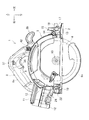
図1は、電動工具の一例である携帯用マルノコ(以下単に「マルノコ」という。)を示す斜視図で、図2は左側面図、図3は正面図、図4は背面図、図5は右側面説明図、図6は平面説明図である。
このマルノコ1は、平面視矩形のベース2上に、モータ4によって回転駆動する円盤状の鋸刃6を備えた本体3を設けてなる。本体3は、モータ4を収容したモータハウジング7と、モータハウジング7に連結されるグリップハウジング8と、鋸刃6の上部を覆うブレードケース9とから形成される。鋸刃6は、ブレードケース9内でモータ4の出力軸5と平行に軸支されて出力軸5から回転伝達される出力部としての回転軸10の先端へ直交状に連結されている。グリップハウジング8には、バッテリー保持部11が形成されて、バッテリー保持部11に電源となる2つのバッテリーパック12,12がスライド装着されている。6aは常態で鋸刃6の下方部分を覆う安全カバーである。
Hereinafter, embodiments of the present invention will be described with reference to the drawings.
FIG. 1 is a perspective view showing a portable maroon saw (hereinafter simply referred to as “marnoko”) as an example of an electric tool. FIG. 2 is a left side view, FIG. 3 is a front view, FIG. 4 is a rear view, and FIG. FIG. 6 is an explanatory diagram on the right side, and FIG.
The marnoco 1 is provided with a
ブレードケース9は、ベース2における切断方向の前方側(図2の右側)が、平面視U字状の連結板13にネジ14によって上下方向へ回転可能に軸着されており、その連結板13が、ベース2上に立設されて円弧状のガイド溝16を有する左右方向のガイド板15に、レバー18を備えたボルト17によってガイド溝16に沿った任意の位置で固定可能に連結されている。一方、ブレードケース9の後方側でも、円弧状のガイド溝20を有する左右方向のガイド板19がベース2上に立設されており、そのガイド板19に、ブレードケース9の側方で前方へ向かって円弧状にカーブするデプスガイド21が、ツマミネジ22によってガイド溝20に沿った任意の位置で固定可能に連結されている。このデプスガイド21に、ブレードケース9の側面に設けたローラ23が貫通して、ローラ23の先端に設けたレバー24によって任意にクランプ操作可能となっている。
The
よって、本体3は、デプスガイド21に沿ったブレードケース9のクランプ位置を変更することで、ネジ14を中心として回転させて、鋸刃6のベース2下方への突出量(切込量)が調整可能となる。また、前後のガイド板15,19における連結板13とデプスガイド21との固定位置を変更することで、本体3を、鋸刃6がベース2と直交する直角位置から、右側へ倒伏して鋸刃6がベース2と45°の角度で傾斜する最大傾斜位置までの任意の傾斜角度で固定可能となる。なお、ベース2の前端には、鋸刃6の直角(0°)位置と45°位置で側縁が夫々鋸刃6の延長上に位置する切込み25,25が形成されており、被切断材の上面に表記した墨線に切込み25の側縁を合わせることで、墨線に沿った切断が容易に可能となっている。
Therefore, the
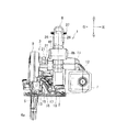
一方、グリップハウジング8は、左右2つ割りの半割ハウジング26,26をネジ27,27・・によって組み付けて形成されるループ状で、上側が一方の手で把持可能なグリップ部8aとなっており、前側には他方の手で把持可能な保持部8bが突設されている。図5は、左側の半割ハウジング26を取り外した状態の説明図で、グリップハウジング8内の下側には、半割ハウジング26の内面に立設したリブ28,28によってコントローラ保持部29が形成され、ここにコントローラ30が収容されている。このコントローラ保持部29の位置で右側の半割ハウジング26には、複数の排気口31,31・・が形成されている。
このコントローラ30は、電気回路基板30aと、この基板上に固定されるスイッチング素子及びマイコンとを有する。電気回路基板30aは、樹脂製の上部開口のケースに収容された状態で、ケースに充填され絶縁性を有する充填部材によりその表面を覆われた状態となる。なお、電気回路基板30aの上面へと、バッテリーパック12,12から第1のリード線により電力が供給されるようになっている。また、電気回路基板30aの上面からモータ4へと第2のリード線が延びている。さらに、電気回路基板30aの上面から後述するリードユニット39へと第3のリード線が延びている。なお、前述した充填部材は、電気回路基板30aと、第1、第2、第3のリード線との接続部をも覆うように形成されている。
On the other hand, the
The
また、グリップ部8a内には、半割ハウジング26の内面に立設したリブ32,32によってスイッチ保持部33が形成され、ここにスイッチ34が収容されている。35は、スイッチ34の図示しないプランジャの前方で軸36を中心に回転可能に設けられ、押し込み操作によってスイッチ34をONさせるトリガ、37は常態でトリガ35の押し込みを阻止する位置に付勢され、左右何れかのスライドによってトリガ35の押し込みを許容するロックオフボタンである。
Further, in the
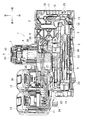
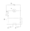
このコントローラ30とスイッチ34、バッテリーパック12,12とモータ4とをリード線38で接続することで、図7に示すように、トリガ35の押し込み操作によってスイッチ34がONするとモータ4が駆動するモータ制御回路が形成されるが、ここではスイッチ34がOFFすると、モータ制御回路内で閉ループが形成され、発電ブレーキ効果を生じさせてモータ4に制動が掛けられるようになっている。この閉ループ内には、ブレーキ電流を制限するためのブレーキ抵抗(ブレーキ用部材)が設けられているが、このブレーキ抵抗として、ここでは寸法の長いリード線が用いられており、グリップハウジング8内で配線しやすいように一箇所で何重にも束ねられてバンド39aで括られたリードユニット39となっている。このリードユニット39は、半割ハウジング26の内面に立設したリブ40によってコントローラ30の前方に形成されるリードユニット保持部41に収容されている。このリードユニット保持部41の位置で右側の半割ハウジング26にも、複数の排気口42,42・・が形成されている。
なお、リードユニットは、抵抗の一種であり、セメント抵抗等を用いることもできる。
By connecting the
The lead unit is a kind of resistance, and cement resistance or the like can also be used.
そして、モータ4の出力軸5には、ファン5aが取り付けられて、出力軸5の回転に伴うファン5aの回転により、モータハウジング7の左端面に形成した吸気口43,43・・から冷却用空気を吸い込み可能となっている。グリップハウジング8は、モータハウジング7と連通していることから、吸気口43から吸い込まれた冷却用空気は、モータ4を通過してグリップハウジング8に至り、ここで分岐して一方はコントローラ30側の排気口31,31・・から排出され、他方はリードユニット39側の排気口42,42・・から排出されることになる(図6の矢印)。
ここでは図5,6に記載のファン5aの径方向外側に、リードユニット39及びコントローラ30が配置されているため、コンパクトな構造となっている。
A
Here, since the
以上の如く構成されたマルノコ1においては、トリガ35を押し込み操作すると、スイッチ34がONしてバッテリーパック12,12からモータ4に電源電圧が供給されてモータ4が駆動し、出力軸5が回転する。よって、回転軸10が回転して鋸刃6が回転し、被切断材を切断可能となる。
一方、トリガ35から指を離すと、スイッチ34がOFF位置となるが、このときモータ4の慣性による回転に伴ってブレーキ電流が発生し、このブレーキ電流が閉回路上にあるリードユニット39に流れ、モータ4の回転を制動することになる。
In the
On the other hand, when the finger is released from the
この出力軸5の回転に伴うファン5aの回転により、吸気口43,43・・から吸い込まれた冷却用空気は、前述のようにモータ4内を通過してモータ4を冷却した後、グリップハウジング8内に至って分岐し、一方はコントローラ30を通過して排気口31,31・・から排出され、他方はリードユニット39を通過して排気口42,42・・から排出される。この空気の流れにより、コントローラ30及びリードユニット39が冷却される。
すなわち、グリップハウジング8には、リードユニット用分岐穴8cとコントローラ用分岐穴8dとが形成されており、モータハウジング7から、ファン5aによって、矢印に記載のように、リードユニット用分岐穴8c及びコントローラ用分岐穴8dへと冷却用空気が移動する。よって、リードユニット39は、下端部から上端部への冷却用空気により冷却される。また、コントローラ30は、ケースの下面に冷却用空気が当たるようになっている。
The cooling air sucked from the
That is, the lead
このように、上記形態のマルノコ1によれば、モータ4の冷却用空気を利用してブレーキ抵抗であるリードユニット39の発熱を好適に抑制することができる。よって、ユーザに不快感を与えたり、部品が熱で破損したりすることを防止可能となる。
Thus, according to the
なお、リードユニットの位置は上記形態に限らず、グリップハウジング内でモータの冷却用空気による冷却が可能であれば、上記形態よりも上方側や後方側に変更しても差し支えない。
また、上記形態では、モータの冷却用空気を分岐させてコントローラも冷却させるようにしているが、冷却用空気を分岐させずにリードユニットのみを冷却させるようにしてもよい。
Note that the position of the lead unit is not limited to the above form, and may be changed to the upper side or the rear side from the above form as long as the motor can be cooled by the cooling air in the grip housing.
In the above embodiment, the cooling air of the motor is branched to cool the controller. However, only the lead unit may be cooled without branching the cooling air.
さらに、上記形態では、冷却用空気は、モータを冷却した後にリードユニット及びコントローラを冷却するようにしているが、リードユニットを冷却した後にモータを冷却するようにしたり、コントローラを冷却した後にモータを冷却するようにしたりしてもよい。
また、グリップハウジングの内部にリードユニットを配置する構成としたが、モータハウジングの内部に配置してもよい。
その他、上記形態では電源となるバッテリーパックを2つ使用した携帯用マルノコを例示して説明しているが、バッテリーパックを1つ使用した携帯用マルノコであってもよいし、充電式に限らずAC電源を使用した携帯用マルノコであってもよい。勿論本発明は携帯用マルノコに限らず、他の電動工具にも適用可能である。
Further, in the above embodiment, the cooling air cools the lead unit and the controller after cooling the motor, but the motor is cooled after the lead unit is cooled, or the motor is cooled after the controller is cooled. It may be cooled.
Further, although the lead unit is arranged inside the grip housing, it may be arranged inside the motor housing.
In addition, although the said form demonstrated and illustrated the portable marine saw using two battery packs used as a power supply, it may be a portable marunoco using one battery pack, and is not limited to a rechargeable type. It may be a portable marunoco using an AC power source. Of course, the present invention is not limited to a portable marnoco but can be applied to other power tools.
1・・携帯用マルノコ、2・・ベース、3・・本体、4・・モータ、5・・出力軸、5a・・ファン、6・・鋸刃、7・・モータハウジング、8・・グリップハウジング、8c・・リードユニット用分岐穴、8d・・コントローラ用分岐穴、9・・ブレードケース、10・・回転軸、11・・バッテリー保持部、12・・バッテリーパック、26・・半割ハウジング、29・・コントローラ保持部、30・・コントローラ、30a・・電気回路基板、31,42・・排気口、35・・トリガ、38・・リード線、39・・リードユニット、41・・リードユニット保持部、43・・吸気口。
1 ...
Claims (4)
前記モータにより駆動される出力部と、
前記モータを収容するモータハウジングと、
前記モータハウジングに接続されるグリップハウジングと、
前記グリップハウジングに設けられるトリガと、を有し、
前記グリップハウジングの内部に、前記モータの回転を制動するためのブレーキ用部材を設けたことを特徴とする電動工具。 A motor that rotates the fan;
An output unit driven by the motor;
A motor housing that houses the motor;
A grip housing connected to the motor housing;
A trigger provided on the grip housing,
An electric tool characterized in that a brake member for braking rotation of the motor is provided inside the grip housing.
前記モータにより駆動される出力部と、
前記モータを収容し、グリップが形成されるハウジングと、
前記グリップに設けられるトリガと、
前記ハウジングに設けられるバッテリー保持部と、を有し、
前記ハウジングの内部に、前記モータの回転を制動するためのブレーキ用部材を設けたことを特徴とする電動工具。 A motor that rotates the fan;
An output unit driven by the motor;
A housing that houses the motor and is formed with a grip;
A trigger provided on the grip;
A battery holding portion provided in the housing,
A power tool characterized in that a brake member for braking the rotation of the motor is provided inside the housing.
前記モータにより回転が負荷され、鋸刃を固定可能な回転軸と、
前記モータを収容するモータハウジングと、
前記モータハウジングに接続されるグリップハウジングと、
前記グリップハウジングに設けられるトリガと、を有し、
前記グリップハウジングの内部に、前記モータの回転を制動するためのブレーキ用部材を設けたことを特徴とする携帯用マルノコ。 A motor that rotates the fan;
Rotation shaft loaded with rotation by the motor and capable of fixing the saw blade;
A motor housing that houses the motor;
A grip housing connected to the motor housing;
A trigger provided on the grip housing,
A portable marnoco characterized in that a brake member for braking the rotation of the motor is provided inside the grip housing.
前記モータにより駆動される出力部と、
前記モータを収容し、グリップが形成され、吸気口及び排気口を有するハウジングと、
前記グリップに設けられるトリガと、を有し、
前記ハウジングの内部で前記吸気口と前記排気口との間に、前記モータの回転を制動するためのブレーキ用部材を配置したことを特徴とする電動工具。 A motor that rotates the fan;
An output unit driven by the motor;
A housing that houses the motor, has a grip, and has an air inlet and an air outlet;
A trigger provided on the grip,
A power tool characterized in that a brake member for braking the rotation of the motor is disposed in the housing between the intake port and the exhaust port.
Priority Applications (4)
| Application Number | Priority Date | Filing Date | Title |
|---|---|---|---|
| JP2013018541A JP2014148006A (en) | 2013-02-01 | 2013-02-01 | Electric power tool and portable circular saw |
| CN201310728219.9A CN103962631A (en) | 2013-02-01 | 2013-12-25 | Power tool and portable circular saw |
| US14/164,128 US9776338B2 (en) | 2013-02-01 | 2014-01-24 | Power tool, such as a portable circular saw, having improved braking and cooling |
| EP14152718.4A EP2762277B1 (en) | 2013-02-01 | 2014-01-27 | Power tool having improved braking |
Applications Claiming Priority (1)
| Application Number | Priority Date | Filing Date | Title |
|---|---|---|---|
| JP2013018541A JP2014148006A (en) | 2013-02-01 | 2013-02-01 | Electric power tool and portable circular saw |
Publications (1)
| Publication Number | Publication Date |
|---|---|
| JP2014148006A true JP2014148006A (en) | 2014-08-21 |
Family
ID=50000843
Family Applications (1)
| Application Number | Title | Priority Date | Filing Date |
|---|---|---|---|
| JP2013018541A Pending JP2014148006A (en) | 2013-02-01 | 2013-02-01 | Electric power tool and portable circular saw |
Country Status (4)
| Country | Link |
|---|---|
| US (1) | US9776338B2 (en) |
| EP (1) | EP2762277B1 (en) |
| JP (1) | JP2014148006A (en) |
| CN (1) | CN103962631A (en) |
Cited By (3)
| Publication number | Priority date | Publication date | Assignee | Title |
|---|---|---|---|---|
| JP2016172302A (en) * | 2015-03-17 | 2016-09-29 | 株式会社マキタ | Cutter |
| JP2019209398A (en) * | 2018-05-31 | 2019-12-12 | 工機ホールディングス株式会社 | Electric power tool |
| US11901850B2 (en) | 2019-12-18 | 2024-02-13 | Milwaukee Electric Tool Corporation | Power tool having stamped brake resistor |
Families Citing this family (18)
| Publication number | Priority date | Publication date | Assignee | Title |
|---|---|---|---|---|
| US9085087B2 (en) * | 2011-12-07 | 2015-07-21 | Chervon (Hk) Limited | Palm jig saw |
| US11685034B2 (en) | 2014-05-24 | 2023-06-27 | Andreas Stihl Ag & Co. Kg | Handheld work apparatus |
| DE102014007878A1 (en) * | 2014-05-24 | 2015-11-26 | Andreas Stihl Ag & Co. Kg | Hand-held implement |
| EP3212369A4 (en) * | 2014-10-30 | 2018-05-16 | Robert Bosch GmbH | Lower blade guard for a circular saw |
| US10404136B2 (en) * | 2015-10-14 | 2019-09-03 | Black & Decker Inc. | Power tool with separate motor case compartment |
| EP3162513B1 (en) * | 2015-10-30 | 2019-04-17 | Black & Decker Inc. | High power brushless motor |
| JP2017124462A (en) * | 2016-01-13 | 2017-07-20 | 株式会社マキタ | Cutting machine |
| EP4008489A1 (en) * | 2016-06-30 | 2022-06-08 | Koki Holdings Co., Ltd. | Electrically powered tool |
| CN109202172A (en) * | 2017-06-30 | 2019-01-15 | 苏州宝时得电动工具有限公司 | Portable electric annular saw |
| JP2019051579A (en) | 2017-09-19 | 2019-04-04 | 株式会社マキタ | Electric work machine |
| US20190111634A1 (en) * | 2017-10-13 | 2019-04-18 | Tti (Macao Commercial Offshore) Limited | Battery powered carpet seamer |
| JP6953288B2 (en) * | 2017-11-14 | 2021-10-27 | 株式会社マキタ | Portable cutting machine |
| CN113909565A (en) * | 2017-12-13 | 2022-01-11 | 南京德朔实业有限公司 | Electric circular saw |
| US10875109B1 (en) | 2018-04-30 | 2020-12-29 | Kreg Enterprises, Inc. | Adaptive cutting system |
| JP7066543B2 (en) * | 2018-06-20 | 2022-05-13 | 株式会社マキタ | Power tools |
| JP7118862B2 (en) * | 2018-10-30 | 2022-08-16 | 株式会社マキタ | Cutting machine |
| JP1687730S (en) * | 2020-09-04 | 2021-06-14 | ||
| US20240009882A1 (en) * | 2022-07-11 | 2024-01-11 | Black & Decker Inc. | Cordless saw having improved cuts per battery charge |
Citations (9)
| Publication number | Priority date | Publication date | Assignee | Title |
|---|---|---|---|---|
| JPH09164501A (en) * | 1995-12-15 | 1997-06-24 | Matsushita Electric Works Ltd | Electric circular saw |
| US20030190877A1 (en) * | 2002-01-10 | 2003-10-09 | William Gallagher | Angle grinder |
| US20040207351A1 (en) * | 2003-04-17 | 2004-10-21 | Dietmar Hahn | Braking device for an electric motor, electrical apparatus provided with the braking device, and a method of braking |
| JP2005223961A (en) * | 2004-02-03 | 2005-08-18 | Hitachi Koki Co Ltd | Motor, power tool comprising it, and process for manufacturing motor |
| JP2008126344A (en) * | 2006-11-17 | 2008-06-05 | Hitachi Koki Co Ltd | Power tool |
| JP2010058186A (en) * | 2008-09-01 | 2010-03-18 | Hitachi Koki Co Ltd | Power tool |
| JP2010201516A (en) * | 2009-02-27 | 2010-09-16 | Hitachi Koki Co Ltd | Power tool |
| JP2011079075A (en) * | 2009-10-05 | 2011-04-21 | Makita Corp | Power tool |
| JP2012178945A (en) * | 2011-02-28 | 2012-09-13 | Makita Corp | Cutting tool |
Family Cites Families (57)
| Publication number | Priority date | Publication date | Assignee | Title |
|---|---|---|---|---|
| US3212188A (en) * | 1962-04-03 | 1965-10-19 | Black & Decker Mfg Co | Cordless electric hedge trimmer |
| US3794898A (en) * | 1973-02-26 | 1974-02-26 | T Gross | Dynamic braking of electric motors with thermistor braking circuit |
| ATE18734T1 (en) * | 1980-12-11 | 1986-04-15 | Black & Decker Inc | CIRCULAR SAW. |
| US4995094A (en) * | 1985-07-19 | 1991-02-19 | Omron Tateisi Electronics Co. | DC motor control circuit providing variable speed operation |
| NL8801466A (en) * | 1988-06-07 | 1990-01-02 | Emerson Electric Co | DEVICE FOR DRIVING A DRILL AND / OR IMPACT TOOL. |
| US5268622A (en) * | 1991-06-27 | 1993-12-07 | Stryker Corporation | DC powered surgical handpiece having a motor control circuit |
| JPH06190628A (en) * | 1992-12-22 | 1994-07-12 | Makita Corp | Circular saw device |
| DE4333064A1 (en) * | 1993-09-29 | 1995-03-30 | Scintilla Ag | Brake circuit for a universal motor |
| DE4333294A1 (en) * | 1993-09-30 | 1995-04-06 | Bosch Gmbh Robert | Electric motor with an electrodynamic brake |
| DE19508881A1 (en) * | 1995-03-11 | 1996-09-12 | Bosch Gmbh Robert | Series motor with braking device |
| DE19508880A1 (en) * | 1995-03-11 | 1996-09-12 | Bosch Gmbh Robert | Circuit for operating an electric motor |
| JP3289123B2 (en) * | 1995-05-09 | 2002-06-04 | 株式会社マキタ | Cutting machine |
| JP3214295B2 (en) * | 1995-05-12 | 2001-10-02 | 日立工機株式会社 | Portable dust collection circular saw |
| US5738177A (en) * | 1995-07-28 | 1998-04-14 | Black & Decker Inc. | Production assembly tool |
| JP3263284B2 (en) | 1995-09-04 | 2002-03-04 | 株式会社マキタ | Electric chainsaw |
| US5685080A (en) | 1996-04-22 | 1997-11-11 | Makita Corporation | Battery powered chain saw |
| US5892885A (en) * | 1998-05-12 | 1999-04-06 | Eaton Corporation | Variable speed control switch for direct current electric power tools |
| US6084366A (en) * | 1998-08-20 | 2000-07-04 | Nuell, Inc. | DC powered hand tools with automatic braking system |
| EP1145421B1 (en) * | 1999-01-07 | 2002-07-24 | Metabowerke GmbH | Mains braking device for a line-powered power tool |
| DE19924552A1 (en) * | 1999-05-28 | 2000-11-30 | Hilti Ag | Electrically powered hand device e.g. electric screwdriver, has cooling air channel arranged downstream of electric motor and gearbox with outflow openings arranged to direct heated air away from user |
| JP3742261B2 (en) * | 1999-11-10 | 2006-02-01 | 株式会社マキタ | Battery pack for electric tools |
| US6676557B2 (en) * | 2001-01-23 | 2004-01-13 | Black & Decker Inc. | First stage clutch |
| AUPR272101A0 (en) * | 2001-01-24 | 2001-02-22 | Bayly Design Associates Pty Ltd | Power tool |
| GB2390488B (en) * | 2002-02-04 | 2006-11-08 | Milwaukee Electric Tool Corp | Electrical devices including a switched reluctance motor |
| US6898854B2 (en) * | 2002-06-07 | 2005-05-31 | Black & Decker Inc. | Modular power tool |
| CA2397024C (en) * | 2002-08-07 | 2008-02-19 | Edward M. Turley | Switch mechanism for reversible grinder |
| DE10242414A1 (en) * | 2002-09-12 | 2004-03-25 | Hilti Ag | Power tool with blower |
| US7023159B2 (en) * | 2002-10-18 | 2006-04-04 | Black & Decker Inc. | Method and device for braking a motor |
| US7075257B2 (en) * | 2002-10-18 | 2006-07-11 | Black & Decker Inc. | Method and device for braking a motor |
| TWI256334B (en) * | 2002-10-22 | 2006-06-11 | Hitachi Koki Kk | Portable electric cutting device with blower mechanism |
| US8286359B2 (en) * | 2002-11-19 | 2012-10-16 | Techtronic Outdoor Products Technology Limited | Battery operated chain saw |
| US7589500B2 (en) * | 2002-11-22 | 2009-09-15 | Milwaukee Electric Tool Corporation | Method and system for battery protection |
| EP1422032B1 (en) * | 2002-11-22 | 2007-03-21 | Robert Bosch Gmbh | Electric hand tool |
| DE10261572A1 (en) * | 2002-12-23 | 2004-07-01 | Robert Bosch Gmbh | Electric hand tool machine e.g. drill, has arrangement for generating additional cooling air flow that passes at least one machine component outside or in low flow region of cooling air flow |
| US7270910B2 (en) * | 2003-10-03 | 2007-09-18 | Black & Decker Inc. | Thermal management systems for battery packs |
| US7526866B2 (en) * | 2003-10-31 | 2009-05-05 | Black & Decker Inc. | Variable dust chute for circular saws |
| JP4467964B2 (en) * | 2003-12-08 | 2010-05-26 | 株式会社マキタ | Dust collection circular saw |
| JP3765425B2 (en) * | 2004-01-26 | 2006-04-12 | 日立工機株式会社 | Portable electric cutting machine |
| ATE502725T1 (en) * | 2004-04-13 | 2011-04-15 | Black & Decker Inc | ELECTRIC GRINDING MACHINE AND ITS MOTOR CONTROL |
| CN1989674B (en) * | 2004-05-24 | 2012-06-13 | 密尔沃基电动工具公司 | Method and system for battery protection |
| ITVI20040157A1 (en) * | 2004-06-29 | 2004-09-29 | Positec Group Ltd | POWER TOOL WITH ERGONOMIC HANDLE AND ROTARY TOOL |
| EP1674211A1 (en) * | 2004-12-23 | 2006-06-28 | BLACK & DECKER INC. | Power tool housing |
| US20070240892A1 (en) * | 2005-11-04 | 2007-10-18 | Black & Decker Inc. | Cordless outdoor power tool system |
| DE602006013863D1 (en) * | 2005-11-04 | 2010-06-02 | Bosch Gmbh Robert | METHOD AND DEVICE FOR A JOINT DRILL |
| AU2008244946B2 (en) * | 2007-04-23 | 2011-04-21 | Hitachi Koki Co., Ltd. | Battery pack and battery-driven power tool using the same |
| DE102007000290A1 (en) * | 2007-05-24 | 2008-11-27 | Hilti Aktiengesellschaft | Electric hand tool with electronic cooling |
| US8067916B2 (en) * | 2008-01-23 | 2011-11-29 | Su Hak Auh | Power cutting tool with synchronized dust control device |
| US8627900B2 (en) * | 2008-05-29 | 2014-01-14 | Hitachi Koki Co., Ltd. | Electric power tool |
| CN102056697B (en) * | 2008-06-10 | 2013-05-29 | 株式会社牧田 | Circular saw |
| JP5017185B2 (en) * | 2008-06-10 | 2012-09-05 | 株式会社マキタ | Power tool |
| CN102149515B (en) * | 2009-01-30 | 2014-08-06 | 日立工机株式会社 | Power tool |
| EP2404374B1 (en) * | 2009-03-03 | 2013-10-09 | Robert Bosch GmbH | Electrodynamic braking device for a universal motor |
| US8328599B2 (en) * | 2009-10-05 | 2012-12-11 | Tai-Her Yang | Internal rotation type direct motor-drive portable angle grinder |
| US20110081847A1 (en) * | 2009-10-05 | 2011-04-07 | Tai-Her Yang | Motor parallel transmission portable angle grinder |
| JP5479023B2 (en) * | 2009-10-20 | 2014-04-23 | 株式会社マキタ | Rechargeable power tool |
| JP5490572B2 (en) * | 2010-03-04 | 2014-05-14 | 株式会社マキタ | Hand-held cutting tool |
| US8446120B2 (en) * | 2011-05-19 | 2013-05-21 | Black & Decker Inc. | Electronic switching module for a power tool |
-
2013
- 2013-02-01 JP JP2013018541A patent/JP2014148006A/en active Pending
- 2013-12-25 CN CN201310728219.9A patent/CN103962631A/en active Pending
-
2014
- 2014-01-24 US US14/164,128 patent/US9776338B2/en active Active
- 2014-01-27 EP EP14152718.4A patent/EP2762277B1/en not_active Not-in-force
Patent Citations (9)
| Publication number | Priority date | Publication date | Assignee | Title |
|---|---|---|---|---|
| JPH09164501A (en) * | 1995-12-15 | 1997-06-24 | Matsushita Electric Works Ltd | Electric circular saw |
| US20030190877A1 (en) * | 2002-01-10 | 2003-10-09 | William Gallagher | Angle grinder |
| US20040207351A1 (en) * | 2003-04-17 | 2004-10-21 | Dietmar Hahn | Braking device for an electric motor, electrical apparatus provided with the braking device, and a method of braking |
| JP2005223961A (en) * | 2004-02-03 | 2005-08-18 | Hitachi Koki Co Ltd | Motor, power tool comprising it, and process for manufacturing motor |
| JP2008126344A (en) * | 2006-11-17 | 2008-06-05 | Hitachi Koki Co Ltd | Power tool |
| JP2010058186A (en) * | 2008-09-01 | 2010-03-18 | Hitachi Koki Co Ltd | Power tool |
| JP2010201516A (en) * | 2009-02-27 | 2010-09-16 | Hitachi Koki Co Ltd | Power tool |
| JP2011079075A (en) * | 2009-10-05 | 2011-04-21 | Makita Corp | Power tool |
| JP2012178945A (en) * | 2011-02-28 | 2012-09-13 | Makita Corp | Cutting tool |
Cited By (4)
| Publication number | Priority date | Publication date | Assignee | Title |
|---|---|---|---|---|
| JP2016172302A (en) * | 2015-03-17 | 2016-09-29 | 株式会社マキタ | Cutter |
| JP2019209398A (en) * | 2018-05-31 | 2019-12-12 | 工機ホールディングス株式会社 | Electric power tool |
| JP7167490B2 (en) | 2018-05-31 | 2022-11-09 | 工機ホールディングス株式会社 | Electric tool |
| US11901850B2 (en) | 2019-12-18 | 2024-02-13 | Milwaukee Electric Tool Corporation | Power tool having stamped brake resistor |
Also Published As
| Publication number | Publication date |
|---|---|
| US20140215839A1 (en) | 2014-08-07 |
| EP2762277B1 (en) | 2018-08-08 |
| US9776338B2 (en) | 2017-10-03 |
| CN103962631A (en) | 2014-08-06 |
| EP2762277A1 (en) | 2014-08-06 |
Similar Documents
| Publication | Publication Date | Title |
|---|---|---|
| JP2014148006A (en) | Electric power tool and portable circular saw | |
| AU2016101611A4 (en) | Hedge trimmer | |
| JP6474764B2 (en) | Cutting machine | |
| CN107175724B (en) | Chain saw | |
| JP6347599B2 (en) | Portable marnoco | |
| US20110180286A1 (en) | Electric Power Tool | |
| JP6100004B2 (en) | Tabletop cutting machine | |
| JP2018176462A (en) | Portable processing machine | |
| JP6238064B2 (en) | Electric plane | |
| US20180207831A1 (en) | Circular saw | |
| US20220297209A1 (en) | Cutting tool | |
| CN109909548B (en) | Electric circular saw | |
| JP6534543B2 (en) | Cutting machine | |
| JP6932620B2 (en) | Portable plane | |
| JP7061915B2 (en) | Circular saw | |
| JP6615851B2 (en) | Tabletop cutting machine | |
| JP2017035784A (en) | Portable circular saw | |
| JP6570701B2 (en) | Portable Marunoko and portable cutting machine | |
| CN212286096U (en) | Cutting tool | |
| JP2018187699A (en) | Electric tool | |
| JP6317001B2 (en) | Tabletop cutting machine | |
| JP2019147216A (en) | Power tool |
Legal Events
| Date | Code | Title | Description |
|---|---|---|---|
| A621 | Written request for application examination |
Free format text: JAPANESE INTERMEDIATE CODE: A621 Effective date: 20150825 |
|
| A977 | Report on retrieval |
Free format text: JAPANESE INTERMEDIATE CODE: A971007 Effective date: 20160413 |
|
| A131 | Notification of reasons for refusal |
Free format text: JAPANESE INTERMEDIATE CODE: A131 Effective date: 20160426 |
|
| A521 | Request for written amendment filed |
Free format text: JAPANESE INTERMEDIATE CODE: A523 Effective date: 20160607 |
|
| A02 | Decision of refusal |
Free format text: JAPANESE INTERMEDIATE CODE: A02 Effective date: 20161025 |