EP1377396B1 - Procede de fabrication de composants structuraux a epaisseur de paroi variable a partir d'ebauches de tubes - Google Patents
Procede de fabrication de composants structuraux a epaisseur de paroi variable a partir d'ebauches de tubes Download PDFInfo
- Publication number
- EP1377396B1 EP1377396B1 EP02712710A EP02712710A EP1377396B1 EP 1377396 B1 EP1377396 B1 EP 1377396B1 EP 02712710 A EP02712710 A EP 02712710A EP 02712710 A EP02712710 A EP 02712710A EP 1377396 B1 EP1377396 B1 EP 1377396B1
- Authority
- EP
- European Patent Office
- Prior art keywords
- tube
- diameter
- mandrel
- die
- wall thickness
- Prior art date
- Legal status (The legal status is an assumption and is not a legal conclusion. Google has not performed a legal analysis and makes no representation as to the accuracy of the status listed.)
- Expired - Lifetime
Links
Images


Classifications
-
- B—PERFORMING OPERATIONS; TRANSPORTING
- B21—MECHANICAL METAL-WORKING WITHOUT ESSENTIALLY REMOVING MATERIAL; PUNCHING METAL
- B21D—WORKING OR PROCESSING OF SHEET METAL OR METAL TUBES, RODS OR PROFILES WITHOUT ESSENTIALLY REMOVING MATERIAL; PUNCHING METAL
- B21D26/00—Shaping without cutting otherwise than using rigid devices or tools or yieldable or resilient pads, i.e. applying fluid pressure or magnetic forces
- B21D26/02—Shaping without cutting otherwise than using rigid devices or tools or yieldable or resilient pads, i.e. applying fluid pressure or magnetic forces by applying fluid pressure
- B21D26/033—Deforming tubular bodies
-
- B—PERFORMING OPERATIONS; TRANSPORTING
- B21—MECHANICAL METAL-WORKING WITHOUT ESSENTIALLY REMOVING MATERIAL; PUNCHING METAL
- B21C—MANUFACTURE OF METAL SHEETS, WIRE, RODS, TUBES OR PROFILES, OTHERWISE THAN BY ROLLING; AUXILIARY OPERATIONS USED IN CONNECTION WITH METAL-WORKING WITHOUT ESSENTIALLY REMOVING MATERIAL
- B21C1/00—Manufacture of metal sheets, metal wire, metal rods, metal tubes by drawing
- B21C1/16—Metal drawing by machines or apparatus in which the drawing action is effected by other means than drums, e.g. by a longitudinally-moved carriage pulling or pushing the work or stock for making metal sheets, bars, or tubes
- B21C1/22—Metal drawing by machines or apparatus in which the drawing action is effected by other means than drums, e.g. by a longitudinally-moved carriage pulling or pushing the work or stock for making metal sheets, bars, or tubes specially adapted for making tubular articles
- B21C1/24—Metal drawing by machines or apparatus in which the drawing action is effected by other means than drums, e.g. by a longitudinally-moved carriage pulling or pushing the work or stock for making metal sheets, bars, or tubes specially adapted for making tubular articles by means of mandrels
-
- B—PERFORMING OPERATIONS; TRANSPORTING
- B21—MECHANICAL METAL-WORKING WITHOUT ESSENTIALLY REMOVING MATERIAL; PUNCHING METAL
- B21C—MANUFACTURE OF METAL SHEETS, WIRE, RODS, TUBES OR PROFILES, OTHERWISE THAN BY ROLLING; AUXILIARY OPERATIONS USED IN CONNECTION WITH METAL-WORKING WITHOUT ESSENTIALLY REMOVING MATERIAL
- B21C37/00—Manufacture of metal sheets, bars, wire, tubes or like semi-manufactured products, not otherwise provided for; Manufacture of tubes of special shape
- B21C37/06—Manufacture of metal sheets, bars, wire, tubes or like semi-manufactured products, not otherwise provided for; Manufacture of tubes of special shape of tubes or metal hoses; Combined procedures for making tubes, e.g. for making multi-wall tubes
- B21C37/065—Manufacture of metal sheets, bars, wire, tubes or like semi-manufactured products, not otherwise provided for; Manufacture of tubes of special shape of tubes or metal hoses; Combined procedures for making tubes, e.g. for making multi-wall tubes starting from a specific blank, e.g. tailored blank
-
- B—PERFORMING OPERATIONS; TRANSPORTING
- B21—MECHANICAL METAL-WORKING WITHOUT ESSENTIALLY REMOVING MATERIAL; PUNCHING METAL
- B21C—MANUFACTURE OF METAL SHEETS, WIRE, RODS, TUBES OR PROFILES, OTHERWISE THAN BY ROLLING; AUXILIARY OPERATIONS USED IN CONNECTION WITH METAL-WORKING WITHOUT ESSENTIALLY REMOVING MATERIAL
- B21C37/00—Manufacture of metal sheets, bars, wire, tubes or like semi-manufactured products, not otherwise provided for; Manufacture of tubes of special shape
- B21C37/06—Manufacture of metal sheets, bars, wire, tubes or like semi-manufactured products, not otherwise provided for; Manufacture of tubes of special shape of tubes or metal hoses; Combined procedures for making tubes, e.g. for making multi-wall tubes
- B21C37/15—Making tubes of special shape; Making tube fittings
- B21C37/16—Making tubes with varying diameter in longitudinal direction
-
- B—PERFORMING OPERATIONS; TRANSPORTING
- B21—MECHANICAL METAL-WORKING WITHOUT ESSENTIALLY REMOVING MATERIAL; PUNCHING METAL
- B21D—WORKING OR PROCESSING OF SHEET METAL OR METAL TUBES, RODS OR PROFILES WITHOUT ESSENTIALLY REMOVING MATERIAL; PUNCHING METAL
- B21D26/00—Shaping without cutting otherwise than using rigid devices or tools or yieldable or resilient pads, i.e. applying fluid pressure or magnetic forces
- B21D26/02—Shaping without cutting otherwise than using rigid devices or tools or yieldable or resilient pads, i.e. applying fluid pressure or magnetic forces by applying fluid pressure
- B21D26/053—Shaping without cutting otherwise than using rigid devices or tools or yieldable or resilient pads, i.e. applying fluid pressure or magnetic forces by applying fluid pressure characterised by the material of the blanks
-
- B—PERFORMING OPERATIONS; TRANSPORTING
- B21—MECHANICAL METAL-WORKING WITHOUT ESSENTIALLY REMOVING MATERIAL; PUNCHING METAL
- B21D—WORKING OR PROCESSING OF SHEET METAL OR METAL TUBES, RODS OR PROFILES WITHOUT ESSENTIALLY REMOVING MATERIAL; PUNCHING METAL
- B21D35/00—Combined processes according to or processes combined with methods covered by groups B21D1/00 - B21D31/00
- B21D35/002—Processes combined with methods covered by groups B21D1/00 - B21D31/00
- B21D35/005—Processes combined with methods covered by groups B21D1/00 - B21D31/00 characterized by the material of the blank or the workpiece
- B21D35/006—Blanks having varying thickness, e.g. tailored blanks
-
- B—PERFORMING OPERATIONS; TRANSPORTING
- B21—MECHANICAL METAL-WORKING WITHOUT ESSENTIALLY REMOVING MATERIAL; PUNCHING METAL
- B21D—WORKING OR PROCESSING OF SHEET METAL OR METAL TUBES, RODS OR PROFILES WITHOUT ESSENTIALLY REMOVING MATERIAL; PUNCHING METAL
- B21D53/00—Making other particular articles
- B21D53/88—Making other particular articles other parts for vehicles, e.g. cowlings, mudguards
Definitions
- the present invention relates to a method of making a generally tubular structural member having a constant outer diameter and a variable wall thickness that is constant circumferentially but variable longitudinally (see for example DE-C-31 33 804 ).
- a final forming process comprising hydroforming, may be carried out.
- tubular blanks In the automotive industry, various structural components are made from tubular blanks. Such blanks are usually formed into the desired component shapes using various forming technologies.
- hydroforming In hydroforming, a tubular blank is placed within a die having a shape of the desired component. The ends of the tube are sealed and a pressurized fluid is applied to the interior of the blank. Such pressure expands the blank until it conforms to the shape of the die cavity.
- the tube blank prior to hydroforming, is bent to the desired shape and the hydroforming step is used to provide the desired cross sectional shape.
- the wall thickness of the tubular blank is generally maintained throughout the forming process, although a slight degree of reduction may be realized due to the stretching of the tube.
- the finished product or component have a variable thickness in order to, inter alia, reduce the overall weight of the final product or to reduce the cost of the materials used to form the component.
- the final product is required to have localized reinforcing in regions that are subjected to stresses, such as bends etc. or, in other cases, regions of weakness so as to preferably facilitate the bending of such sections.
- Various methods have been suggested to provide such variable wall product.
- the method taught in US Patent 5,333,775 involves a number of tubular pieces of different wall thicknesses to be welded together to form the blank used in the hydroforming step.
- this method includes various deficiencies. Firstly, the method involves the pre-forming step of creating the multiwall blank using a welding procedure, which adds a considerable amount to the total processing time. Secondly, the presence of welds may lead to weak spots in the formed product
- US Patent 5,557,961 teaches a method wherein the tubular blank is provided with a constant outer diameter, and which is used in a hydroforming process.
- the wall thickness of the blank taught in this reference varies circumferentially but is constant in the longitudinal direction.
- the blank is provided with longitudinal grooves along the interior surface.
- the component formed according the the '961 method includes thin sections, at any given cross section, wherein such thin sections extend along the length of the component.
- This reference does not, however, teach a formed component having a constant cross sectional or circumferential wall thickness.
- European Patent No. 0,760,265 discloses the manufacturing of a tube, having reduced wall thickness at certain sections and which can be used to form an axle for a vehicle.
- the tube is formed by hydroforming the tube.
- German Patent No. 197 51 408 discloses a method of forming a tube with reduced wall thickness along a longitudinal axis of the tube, while maintaining a constant inner diameter and a variable outer diameter in correspondence of the reduced wall thicknesses.
- DE-C-31 33 804 discloses a method of the kind of the present invention using a stepped mandrel.
- the present invention provides an improved method for providing a formed product having a variable longitudinal wall thickness that overcomes at least some of the deficiencies discussed above.
- the invention provides a method of making a generally tubular structural member according to claim 1.
- Figure 1 illustrates a tubular blank obtained by the method of the present invention.
- the blank 10 comprises a tubular member having a generally uniform outer surface 12 and a generally uniform outer diameter D1.
- the blank 10 is formed with a variable wall thickness, as described further below, such that at desired portions, the wall thickness is reduced thereby resulting in a larger inner diameter.
- Figure 1 illustrates two such reduced wall regions as 14 and 16.
- the blank is originally provided with a wall thickness t1.
- the wall thickness is reduced to t2 and at the second reduced thickness region, 16, the wall thickness is reduced to t3.
- t2 and t3 may be the same or different depending upon the specific characteristics of the required blank.
- Figures 2 and 3 illustrate, respectively, the wall thicknesses of the blank at a non-reduced thickness region and a reduced thickness region. As can be seen, the wall thickness of each region is circumferentially uniform.
- the reduced thickness regions discussed above can be formed by any means known in the art.
- An example of such process is provided in US Patent 4,616,500 .
- the blank is formed by passing a tube of constant wall thickness through a die and mandrel assembly.
- the mandrel is preferably of a reciprocating type that can be inserted and withdrawn from the die using a control apparatus.
- the die is co-axial with the tube and is provided in the interior thereof.
- the tube is pulled through the die resulting in a constant outer diameter.
- the mandrel is inserted into the die cavity at specific times so as to reduce the wall thickness of the tube at desired locations along its length. In this manner, a tubular blank is formed having the desired regions of reduced wall thickness,
- the formed tube obtained from the die and mandrel process may be cut to a desired length to result in the tube blank to be used in the method of the invention.
- the assembly 18 comprises a die 20 having a die cavity 22.
- a mandrel 24 is provided at one end of a rod 26.
- the rod 26 is attached, at its other end, to a control mechanism that allows the mandrel to be inserted and withdrawn from the die cavity 22 in a reciprocating manner as indicated by arrow 28.
- a tube 30 is attached at a first end to a draw machine, not shown, as is known in the art. The first end of the tube is then drawn through the die cavity so as to result in a drawn tube 31 having a constant outer diameter. The direction in which the tube is drawn is indicated by the arrow 32.
- the die cavity 22 is provided with a first opening 34 having a diameter to allow the passage of tube 30 and a second opening 36 having a diameter to allow the passage of tube 31.
- the diameter of opening 36 is less than that of opening 34. Accordingly, the diameter of the drawn tube 31 is generally less than that of the original tube 30.
- the mandrel 24 is positioned within the interior of the tube 30 and is generally co-axial therewith. If the mandrel is moved into the die cavity 22, the wall of the tube 30 passing through the die cavity 22 is constricted. If the mandrel is removed from the die cavity, such constriction is not effected. Therefore, by reciprocating the mandrel 24 in and out of the die cavity 22 while the tube 30 is drawn there-through, the resulting drawn tube 31 may be provided with regions of thinned walls along the length thereof, while maintaining a constant outer diameter. As illustrated in Figure 4 , the drawn tube 31 includes thin wall regions 38 and 40, separated by a region where the wall thickness is not affected, 42.
- the process of drawing the tube 30 through the die cavity 22 may impart a change in the wall thickness in the absence of any mandrel.
- such change in wall thickness will be generally uniform thereby resulting in the drawn tube 31 having generally uniform inner and outer diameters.
- the drawn tube 31 described above may be cut to the desired length, if needed, thereby resulting in the tube blank 10.
- the desired length may be cut prior to inserting into the die and mandrel assembly, whereby the drawn tube 31 comprises the tube blank itself.
- the blank is then further processed, where necessary, and formed to the desired final shape as described further below.
- the blank 10 is first bent in the desired two or three dimensional shape.
- the final forming stage such a hydroforming stage, is used to impart the desired cross sectional shape or shapes.
- the tube blank is delivered to a forming station.
- a forming station comprises a hydroforming station as is commonly known in the art.
- An example of a typical hydroforming apparatus is illustrated in Figure 5 .
- a hydroforming apparatus generally includes a die 45 having two sections 44 and 46. Each of sections 44 and 46 are provided with one half of a die cavity 48.
- the die cavity 48 is formed with the desired overall and cross sectional shape of the final component being made.
- a tube blank 50 is placed within the die cavity when in the open position, as shown in Figures 5 and 6 . As can be seen, the tube blank 50 is initially formed in the desired general shape of the desired element, including the required bends etc. Once in the die cavity 48, the sections 44 and 46 are closed, wherein both sections are in contact thereby forming and sealing the cavity 48.
- the blank prior to the hydroforming phase, the blank is first bent into the desired shape.
- the blank prior to such bending, the blank is first subjected to a heat treatment, or stress relief process in order to impart the desired formability characteristics to the blank.
- a heat treatment, or stress relief process in order to impart the desired formability characteristics to the blank.
- the physical characteristics of the blank will depend upon the formed product that is desired.
- a pre-bending or pre-forming step may be carried out but is not needed for all components.
- the present invention provides a formed component that is homogenous with respect to material properties and one that avoids the need for numerous welded joints.
- the method of the present invention can be used to make any tubular structural member. More specifically, the method of the invention is particularly suited for the manufacture of tubular components in the automotive industry. Such components include: axles; twist axles engine cradles; side rails (frame); transmission cross members; suspension components; and instrument panel cross members. As will be appreciated by persons skilled in the art, various other components, for use in any type of industry, may be manufactured by the method of the invention.
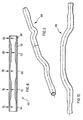
- FIG. 8 An example of a component manufactured according to the method of the invention is illustrate in Figures 8 to 13 , wherein a vehicle axle is formed.
- a tube blank 60 is illustrated.
- the blank 60 has an outer surface 62 with a generally uniform outer diameter.
- the blank 60 is provided with 3 regions of reduced inner diameter, 64, 66 and 68, respectively. Accordingly, the blank 60 is thus provided with two regions, 70 and 72, of a larger inner diameter. Due to the constant outer diameter, the difference in inner diameter leads to different wall thicknesses in the regions 64 to 72. In the preferred embodiment, such differences in wall thickness are achieved by the reciprocating mandrel and die assembly discussed above.
- the various regions are formed with wall thicknesses 74, 76, 78, 80 and 82 in the following dimensions: Section Wall Thickness 74 3 mm 76 5 mm 78 3.4 mm 80 5 mm 82 3 mm
- the initial tube, prior to the die forming step had a generally constant wall thickness of 5 mm and a length of approximately 1.77 m.
- Figures 9, 10 and 11 illustrate the axle 90 formed using the blank 60 of Figure 8 .
- the axle 90 includes a number of bends, which were formed by bending the blank 60. After the bending process, the blank was then hydroformed in a conventional manner to provide the desired cross sectional shapes. Such shapes are illustrated in Figure 12 and 13 .
- the cross sections shown in Figure 12 A-E have the following wall thicknesses: Figure Wall Thickness 12 A 3mm 12 B 3 mm 12 C 5 mm 12 D 5 mm 12 E 3.4 mm
Landscapes
- Engineering & Computer Science (AREA)
- Mechanical Engineering (AREA)
- Physics & Mathematics (AREA)
- Fluid Mechanics (AREA)
- Shaping Metal By Deep-Drawing, Or The Like (AREA)
Abstract
Claims (10)
- Procédé de fabrication d'un élément structurel généralement tubulaire ayant un diamètre extérieur constant et une épaisseur de paroi variable qui est constante circonférentiellement, mais variable longitudinalement, le procédé comprenant l'étape consistant à fournir un tube (30) ayant des diamètres extérieur et intérieur initiaux et une épaisseur de paroi initiale, et des première et seconde extrémités, et comprenant les étapes consistant à :- fournir une matrice (20) ayant une cavité de matrice (22) pour recevoir ledit tube, ladite cavité de matrice (22) ayant un premier diamètre (36) et un second diamètre (34), ledit second diamètre (34) étant plus grand que le premier diamètre (36), et une partie tronconique s'étendant entre lesdits premier et second diamètres,- fournir un mandrin généralement cylindrique (24), ledit mandrin (24) étant adapté pour être inséré dans ledit tube (30), et ayant une première extrémité reliée à une tige de support (26) et une seconde extrémité opposée, ladite première extrémité de mandrin ayant un premier diamètre, et ladite seconde extrémité de mandrin ayant un second diamètre, le second diamètre étant inférieur au premier diamètre d'extrémité, dans lequel le mandrin (24) comprend une partie tronconique s'étendant entre lesdits première et seconde extrémités, et dans lequel le premier diamètre de ladite matrice (20) est inférieur au premier diamètre du mandrin, mais supérieur au second diamètre du mandrin,- insérer la première extrémité dudit tube (30) à travers ladite cavité de matrice (22), et amener ledit tube (30) et ladite matrice (2) à se déplacer l'un par rapport à l'autre le long de l'axe longitudinal dudit tube (30), de sorte que ledit tube (30) est étiré à travers la cavité de matrice (22) dans une direction orientée depuis le second diamètre (34) vers le premier diamètre (36), en dotant ainsi le tube (30) d'un diamètre extérieur constant correspondant audit premier diamètre (36) de la cavité de matrice (22),- insérer ledit mandrin (24) dans ledit tube (30) à travers la seconde extrémité du tube (30),- faire avancer ledit mandrin (24) en va-et-vient par rapport à ladite cavité de matrice (22) lorsque le tube est étiré à travers la matrice, de sorte que l'épaisseur de paroi du tube (30) est réduite par constriction entre la partie tronconique de la matrice et la partie tronconique du mandrin lorsque la première extrémité du mandrin est avancée vers ledit premier diamètre de matrice (36).
- Procédé selon la revendication 1, dans lequel le second diamètre de ladite cavité de matrice (22) est plus petit que le diamètre extérieur initial dudit tube (30), de sorte qu'un déplacement relatif de ladite matrice (20) et dudit tube (30) a pour résultat une réduction du diamètre extérieur initial dudit tube (30).
- Procédé selon la revendication 2, dans lequel ladite matrice (20) est maintenue stationnaire, et ledit tube (30) est étiré à travers celle-ci.
- Procédé selon la revendication 3, dans lequel ladite première extrémité de mandrin est avancée vers ledit premier diamètre de matrice lorsque ladite matrice (20) chevauche un tronçon dudit tube (30) où une réduction d'épaisseur de paroi est souhaitée.
- Procédé selon l'une quelconque des revendications précédentes, dans lequel ledit procédé est effectué sous des conditions de formage à froid.
- Procédé selon l'une quelconque des revendications précédentes, comportant en outre le recuit ou le traitement thermique d'au moins une partie du tube formé (30).
- Procédé selon la revendication 6, comprenant en outre une étape d'incurvation, qui suit l'étape de recuit ou de traitement thermique, dans lequel l'ébauche tubulaire est incurvée à des emplacements souhaités.
- Procédé selon l'une quelconque des revendications précédentes, comprenant en outre le formage dudit tube ayant l'épaisseur de paroi variable (30) en une forme tridimensionnelle souhaitée.
- Procédé selon l'une quelconque des revendications précédentes, dans lequel un déplacement du mandrin est effectué par un mécanisme de commande fixé de manière opérationnelle sur le mandrin, et un déplacement du tube est effectué par une machine d'étirage fixée de manière opérationnelle sur le tube, et dans lequel un déplacement du mandrin est indépendant du tube.
- Procédé selon l'une quelconque des revendications précédentes, dans lequel ledit tube est muni de plus de deux épaisseurs de paroi différentes le long de sa longueur.
Applications Claiming Priority (3)
| Application Number | Priority Date | Filing Date | Title |
|---|---|---|---|
| CA002342702A CA2342702A1 (fr) | 2001-04-04 | 2001-04-04 | Methode de formage utilisant des tubes bruts a parois a epaisseurs variables |
| CA2342702 | 2001-04-04 | ||
| PCT/CA2002/000464 WO2002081115A1 (fr) | 2001-04-04 | 2002-04-04 | Procede de fabrication de composants structuraux a partir d'ebauches de tubes a epaisseur de paroi variable |
Publications (2)
| Publication Number | Publication Date |
|---|---|
| EP1377396A1 EP1377396A1 (fr) | 2004-01-07 |
| EP1377396B1 true EP1377396B1 (fr) | 2008-12-24 |
Family
ID=4168756
Family Applications (1)
| Application Number | Title | Priority Date | Filing Date |
|---|---|---|---|
| EP02712710A Expired - Lifetime EP1377396B1 (fr) | 2001-04-04 | 2002-04-04 | Procede de fabrication de composants structuraux a epaisseur de paroi variable a partir d'ebauches de tubes |
Country Status (6)
| Country | Link |
|---|---|
| US (1) | US8141404B2 (fr) |
| EP (1) | EP1377396B1 (fr) |
| CA (1) | CA2342702A1 (fr) |
| DE (1) | DE60230494D1 (fr) |
| MX (1) | MXPA03009049A (fr) |
| WO (1) | WO2002081115A1 (fr) |
Cited By (1)
| Publication number | Priority date | Publication date | Assignee | Title |
|---|---|---|---|---|
| DE102010027093A1 (de) | 2010-07-13 | 2012-01-19 | Benteler Automobiltechnik Gmbh | Verfahren zur Herstellung eines Hohlprofils aus Metall |
Families Citing this family (22)
| Publication number | Priority date | Publication date | Assignee | Title |
|---|---|---|---|---|
| SE519170C2 (sv) * | 2002-03-07 | 2003-01-21 | Finnveden Technology Ab | Process vid framställning av slutna härdade profiler utan tvärsnittsbegränsningar |
| CA2841707C (fr) | 2004-10-28 | 2016-03-29 | U.S. Manufacturing Corporation | Ensemble de carter d'essieu tubulaire avec epaisseur de paroi variable |
| US7334312B2 (en) * | 2005-02-23 | 2008-02-26 | U.S. Manufacturing Corporation | Method of forming axles with internally thickened wall sections |
| US20070283562A1 (en) * | 2006-06-05 | 2007-12-13 | Benteler Automotive Corporation | Method for making a non-driving vehicle axle beam |
| KR100958977B1 (ko) * | 2007-07-25 | 2010-05-20 | 주식회사 포스코 | 자동차의 후륜 현가장치용 튜브형 토션 빔 및 그 제조방법 |
| CA2644464C (fr) * | 2008-10-17 | 2010-04-20 | Arcelormittal Tubular Products Canada Inc. | Essieu a torsion a epaisseur de paroi progressive |
| DE102009026297B4 (de) * | 2009-07-31 | 2013-08-08 | Thyssenkrupp Steel Europe Ag | Cockpitquerträger mit variablem Lenksäulenneigungswinkel |
| DE102011113662A1 (de) | 2011-09-19 | 2013-03-21 | Benteler Automobiltechnik Gmbh | Strukturbauteil für ein Kraftfahrzeug mit einem hohlförmigen Grundprofil sowie Verfahren zu dessen Herstellung |
| CN102989857A (zh) * | 2012-09-14 | 2013-03-27 | 黄启瑞 | 金属板材的成型方法 |
| DE102013020587A1 (de) * | 2012-12-14 | 2014-06-18 | Salzgitter Hydroforming GmbH & Co. KG | Verfahren zur Herstellung von nachträglich ausgebildeten partiellen Wandstärkenreduzierungen an Halbzeugen mit Hohlraumausbildung |
| EP2746155B1 (fr) * | 2012-12-21 | 2015-07-08 | Bell Helicopter Textron Inc. | Train d'atterrissage à patins d'hélicoptère |
| CN103736811B (zh) * | 2014-01-23 | 2016-04-27 | 哈尔滨工业大学 | 采用轴向不等壁厚管坯成形等壁厚变直径管件的方法 |
| US10040108B2 (en) | 2014-09-18 | 2018-08-07 | L&W Engineering | Tubular structure support with variable dimensions and mechanical properties |
| DE102016206640A1 (de) * | 2016-04-20 | 2017-10-26 | Thyssenkrupp Ag | Trägerrohr einer Nockenwelle mit variierender Wandstärke |
| CN108357447B (zh) * | 2018-01-15 | 2020-01-14 | 长安大学 | 一种梯度刻槽缓冲吸能元件及其制备方法 |
| CN108266480A (zh) * | 2018-01-15 | 2018-07-10 | 长安大学 | 一种梯度深度刻槽缓冲吸能元件及其制备方法 |
| CN108194545A (zh) * | 2018-01-15 | 2018-06-22 | 长安大学 | 一种梯度宽度刻槽缓冲吸能元件及其制备方法 |
| US11122741B2 (en) * | 2018-01-30 | 2021-09-21 | Cnh Industrial America Llc | Stalk roller assembly for an agricultural system |
| US11384810B2 (en) | 2018-10-22 | 2022-07-12 | Tenneco Automotive Operating Company Inc. | Damper with two-piece shell |
| GB201903228D0 (en) * | 2019-03-11 | 2019-04-24 | Nicoventures Trading Ltd | Aerosol generation device heater element manufacture |
| JP7303718B2 (ja) * | 2019-10-01 | 2023-07-05 | 住友重機械工業株式会社 | 成形装置及びブロー成形用の金属パイプ材料 |
| CN115319412B (zh) * | 2022-08-08 | 2023-06-06 | 四川航天中天动力装备有限责任公司 | 一种变壁厚壳体加工工艺方法 |
Citations (2)
| Publication number | Priority date | Publication date | Assignee | Title |
|---|---|---|---|---|
| FR1259364A (fr) * | 1958-01-07 | 1961-04-28 | T I Aluminium Ltd | Perfectionnements à la fabrication des tubes |
| DE3133804C1 (de) * | 1981-08-24 | 1983-05-05 | Mannesmann AG, 4000 Düsseldorf | Regeleinrichtung zum Einstellen der Lage eines Stufendorns |
Family Cites Families (26)
| Publication number | Priority date | Publication date | Assignee | Title |
|---|---|---|---|---|
| US2240456A (en) * | 1939-10-06 | 1941-04-29 | Republic Steel Corp | Apparatus for producing tubular articles having varying wall thickness |
| US2258242A (en) * | 1940-09-27 | 1941-10-07 | Phelps Dodge Copper Prod | Apparatus for drawing tubes of multiple wall thickness |
| FR1569006A (fr) | 1968-03-25 | 1969-05-30 | ||
| US3572080A (en) * | 1968-10-03 | 1971-03-23 | George A Mitchell Co | Production of pointed workpieces |
| US3789650A (en) * | 1972-07-28 | 1974-02-05 | Mitchell Co | Method for forming reduced diameter ends on elongated workpieces |
| US3754428A (en) * | 1972-07-28 | 1973-08-28 | Mitchell G Co | Method and apparatus for severing tubing |
| US4484756A (en) * | 1981-11-04 | 1984-11-27 | Bridgestone Cycle Co., Ltd. | Blank tube and main frame for two-wheeled vehicle |
| US4726211A (en) * | 1984-04-16 | 1988-02-23 | Sanwa Kokan Kabushiki Kaishas | Method of cold drawing seamless metal tubes each having an upset portion on each end |
| US4616500A (en) * | 1985-02-25 | 1986-10-14 | George A. Mitchell Company | Method for producing tubing of varying wall thickness |
| JPS62224421A (ja) * | 1986-03-25 | 1987-10-02 | Nhk Spring Co Ltd | 中空スタビライザの製造方法 |
| US4799412A (en) * | 1986-10-14 | 1989-01-24 | George A. Mitchell Company | Method for severing the ends of tubing |
| US4744237A (en) * | 1987-05-06 | 1988-05-17 | Ti Automotive Division Of Ti Canada Inc. | Method of forming box-like frame members |
| US4759111A (en) * | 1987-08-27 | 1988-07-26 | Ti Automotive Division Of Ti Canada Inc. | Method of forming reinforced box-selection frame members |
| US5170557A (en) * | 1991-05-01 | 1992-12-15 | Benteler Industries, Inc. | Method of forming a double wall, air gap exhaust duct component |
| US5333775A (en) * | 1993-04-16 | 1994-08-02 | General Motors Corporation | Hydroforming of compound tubes |
| US5339667A (en) * | 1993-04-19 | 1994-08-23 | General Motors Corporation | Method for pinch free tube forming |
| EP0760265A1 (fr) | 1995-08-26 | 1997-03-05 | Benteler Ag | Tube pour application à la fabrication d'éléments pour essieu de véhicule automobile et essieu de véhicule automobile avec un tel tube |
| US5557961A (en) * | 1995-11-13 | 1996-09-24 | General Motors Corporation | Hydroformed structural member with varied wall thickness |
| US5882039A (en) * | 1997-01-23 | 1999-03-16 | Dana Corporation | Hydroformed engine cradle and cross member for vehicle body and frame assembly |
| HUP0004299A3 (en) * | 1997-10-16 | 2002-03-28 | Cosma Internat Inc Aurora | Space frame for a motor vehicle and method of manufacturing the same |
| DE19751408C2 (de) * | 1997-11-14 | 1999-10-21 | Mannesmann Ag | Verfahren und Vorrichtung zur Herstellung eines Integralgehäuses für Hydrolenkung |
| JP2000301251A (ja) * | 1998-12-31 | 2000-10-31 | Dana Corp | 前車軸ビームのハイドロフォーム法による製造方法 |
| US6032501A (en) * | 1999-02-09 | 2000-03-07 | The Budd Company | Method of hydroforming multi-lateral members from round tubes |
| US6183013B1 (en) * | 1999-07-26 | 2001-02-06 | General Motors Corporation | Hydroformed side rail for a vehicle frame and method of manufacture |
| WO2001088384A1 (fr) * | 2000-05-12 | 2001-11-22 | Ptc Alliance, Inc. | Ebauches de tubes pour hydroformage |
| EP1177843A3 (fr) | 2000-08-03 | 2003-06-11 | Pittsburg Tube Co. | Procédé et dispositif de formation de tubes |
-
2001
- 2001-04-04 CA CA002342702A patent/CA2342702A1/fr not_active Abandoned
-
2002
- 2002-04-04 US US10/474,238 patent/US8141404B2/en not_active Expired - Fee Related
- 2002-04-04 MX MXPA03009049A patent/MXPA03009049A/es unknown
- 2002-04-04 EP EP02712710A patent/EP1377396B1/fr not_active Expired - Lifetime
- 2002-04-04 DE DE60230494T patent/DE60230494D1/de not_active Expired - Lifetime
- 2002-04-04 WO PCT/CA2002/000464 patent/WO2002081115A1/fr not_active Application Discontinuation
Patent Citations (2)
| Publication number | Priority date | Publication date | Assignee | Title |
|---|---|---|---|---|
| FR1259364A (fr) * | 1958-01-07 | 1961-04-28 | T I Aluminium Ltd | Perfectionnements à la fabrication des tubes |
| DE3133804C1 (de) * | 1981-08-24 | 1983-05-05 | Mannesmann AG, 4000 Düsseldorf | Regeleinrichtung zum Einstellen der Lage eines Stufendorns |
Cited By (1)
| Publication number | Priority date | Publication date | Assignee | Title |
|---|---|---|---|---|
| DE102010027093A1 (de) | 2010-07-13 | 2012-01-19 | Benteler Automobiltechnik Gmbh | Verfahren zur Herstellung eines Hohlprofils aus Metall |
Also Published As
| Publication number | Publication date |
|---|---|
| US20040200255A1 (en) | 2004-10-14 |
| DE60230494D1 (de) | 2009-02-05 |
| US8141404B2 (en) | 2012-03-27 |
| WO2002081115A1 (fr) | 2002-10-17 |
| CA2342702A1 (fr) | 2002-10-04 |
| MXPA03009049A (es) | 2004-04-02 |
| EP1377396A1 (fr) | 2004-01-07 |
Similar Documents
| Publication | Publication Date | Title |
|---|---|---|
| EP1377396B1 (fr) | Procede de fabrication de composants structuraux a epaisseur de paroi variable a partir d'ebauches de tubes | |
| KR970010546B1 (ko) | 보강시킨 박스단면형 프레임 부재의 성형방법 | |
| EP0195157A2 (fr) | Procédé pour le façonnage de cadres en forme de caisse | |
| KR100517584B1 (ko) | 하이드로폼 성형된 각진 관형 부품 및 이를 제조하기 위한방법 및 장치 | |
| US5333775A (en) | Hydroforming of compound tubes | |
| US20060201227A1 (en) | Vehicle structural components made from tubular members and method therefor | |
| EP1272291B1 (fr) | Procede de fabrication d'un element tubulaire | |
| JP2002523239A (ja) | チューブ状部材の製造方法 | |
| US5802899A (en) | Method for internal high-pressure deforming of hollow offset shafts made of cold-deformable metal | |
| US7013697B2 (en) | Method for expanding a tubular blank | |
| CA2483113C (fr) | Procede d'etirage a froid d'extremite de tubes | |
| JP2832702B2 (ja) | 二重管の製造方法 | |
| US7143618B2 (en) | Method of making pre-formed tubular members | |
| US6044678A (en) | Method and device for manufacturing a tubular hollow body with spaced-apart increased diameter portions | |
| US6401509B1 (en) | Method for producing a hollow body made of metal | |
| US6112567A (en) | Method and apparatus for manufacturing a hollow body from a tubular blank by internal high-pressure shaping | |
| US7370504B2 (en) | Method of making variable thickness tubular member for vehicles | |
| CA2442430C (fr) | Procede de fabrication de composants structuraux a partir d'ebauches de tubes a epaisseur de paroi variable | |
| EP1154870B1 (fr) | Procede pour deformer un morceau de tube metallique a paroi mince | |
| US20020063145A1 (en) | Reinforced hydroform tube | |
| US7059033B2 (en) | Method of forming thickened tubular members | |
| US7251972B2 (en) | Method and device for reshaping tubes | |
| EP0770435A1 (fr) | Méthode de fabrication d'une pièce de construction et support d'essieu | |
| KR20050068051A (ko) | 하이드로포밍을 이용한 고강도 스테인레스 엔진크레이들제조방법 | |
| JPS62214821A (ja) | 中空ピストンロツドの製造方法 |
Legal Events
| Date | Code | Title | Description |
|---|---|---|---|
| PUAI | Public reference made under article 153(3) epc to a published international application that has entered the european phase |
Free format text: ORIGINAL CODE: 0009012 |
|
| 17P | Request for examination filed |
Effective date: 20031103 |
|
| AK | Designated contracting states |
Kind code of ref document: A1 Designated state(s): AT BE CH CY DE DK ES FI FR GB GR IE IT LI LU MC NL PT SE TR |
|
| AX | Request for extension of the european patent |
Extension state: AL LT LV MK RO SI |
|
| 17Q | First examination report despatched |
Effective date: 20050323 |
|
| RAP1 | Party data changed (applicant data changed or rights of an application transferred) |
Owner name: DOFASCO TUBULAR PRODUCTS INC. |
|
| 17Q | First examination report despatched |
Effective date: 20050323 |
|
| 17Q | First examination report despatched |
Effective date: 20050323 |
|
| GRAP | Despatch of communication of intention to grant a patent |
Free format text: ORIGINAL CODE: EPIDOSNIGR1 |
|
| RTI1 | Title (correction) |
Free format text: METHOD OF MANUFACTURING STRUCTURAL COMPONENTS HAVING VARIABLE WALL THICKNESS FROM TUBE BLANKS |
|
| GRAS | Grant fee paid |
Free format text: ORIGINAL CODE: EPIDOSNIGR3 |
|
| GRAA | (expected) grant |
Free format text: ORIGINAL CODE: 0009210 |
|
| RAP1 | Party data changed (applicant data changed or rights of an application transferred) |
Owner name: ARCELORMITTAL TUBULAR PRODUCTS CANADA INC. |
|
| AK | Designated contracting states |
Kind code of ref document: B1 Designated state(s): DE FR GB IT |
|
| REG | Reference to a national code |
Ref country code: GB Ref legal event code: FG4D |
|
| REF | Corresponds to: |
Ref document number: 60230494 Country of ref document: DE Date of ref document: 20090205 Kind code of ref document: P |
|
| PLBE | No opposition filed within time limit |
Free format text: ORIGINAL CODE: 0009261 |
|
| STAA | Information on the status of an ep patent application or granted ep patent |
Free format text: STATUS: NO OPPOSITION FILED WITHIN TIME LIMIT |
|
| 26N | No opposition filed |
Effective date: 20090925 |
|
| PG25 | Lapsed in a contracting state [announced via postgrant information from national office to epo] |
Ref country code: IT Free format text: LAPSE BECAUSE OF FAILURE TO SUBMIT A TRANSLATION OF THE DESCRIPTION OR TO PAY THE FEE WITHIN THE PRESCRIBED TIME-LIMIT Effective date: 20081224 |
|
| REG | Reference to a national code |
Ref country code: FR Ref legal event code: PLFP Year of fee payment: 15 |
|
| REG | Reference to a national code |
Ref country code: FR Ref legal event code: PLFP Year of fee payment: 16 |
|
| REG | Reference to a national code |
Ref country code: FR Ref legal event code: PLFP Year of fee payment: 17 |
|
| PGFP | Annual fee paid to national office [announced via postgrant information from national office to epo] |
Ref country code: FR Payment date: 20210323 Year of fee payment: 20 |
|
| PGFP | Annual fee paid to national office [announced via postgrant information from national office to epo] |
Ref country code: GB Payment date: 20210324 Year of fee payment: 20 |
|
| PGFP | Annual fee paid to national office [announced via postgrant information from national office to epo] |
Ref country code: DE Payment date: 20210323 Year of fee payment: 20 |
|
| REG | Reference to a national code |
Ref country code: DE Ref legal event code: R071 Ref document number: 60230494 Country of ref document: DE |
|
| REG | Reference to a national code |
Ref country code: GB Ref legal event code: PE20 Expiry date: 20220403 |
|
| PG25 | Lapsed in a contracting state [announced via postgrant information from national office to epo] |
Ref country code: GB Free format text: LAPSE BECAUSE OF EXPIRATION OF PROTECTION Effective date: 20220403 |