EP1376823A2 - Stator winding coil ends fastening device for an alternator - Google Patents
Stator winding coil ends fastening device for an alternator Download PDFInfo
- Publication number
- EP1376823A2 EP1376823A2 EP03012054A EP03012054A EP1376823A2 EP 1376823 A2 EP1376823 A2 EP 1376823A2 EP 03012054 A EP03012054 A EP 03012054A EP 03012054 A EP03012054 A EP 03012054A EP 1376823 A2 EP1376823 A2 EP 1376823A2
- Authority
- EP
- European Patent Office
- Prior art keywords
- stator
- coil end
- conductor
- lead wires
- alternator
- Prior art date
- Legal status (The legal status is an assumption and is not a legal conclusion. Google has not performed a legal analysis and makes no representation as to the accuracy of the status listed.)
- Granted
Links
Images


Classifications
-
- H—ELECTRICITY
- H02—GENERATION; CONVERSION OR DISTRIBUTION OF ELECTRIC POWER
- H02K—DYNAMO-ELECTRIC MACHINES
- H02K3/00—Details of windings
- H02K3/46—Fastening of windings on the stator or rotor structure
- H02K3/50—Fastening of winding heads, equalising connectors, or connections thereto
-
- H—ELECTRICITY
- H02—GENERATION; CONVERSION OR DISTRIBUTION OF ELECTRIC POWER
- H02K—DYNAMO-ELECTRIC MACHINES
- H02K3/00—Details of windings
- H02K3/46—Fastening of windings on the stator or rotor structure
- H02K3/50—Fastening of winding heads, equalising connectors, or connections thereto
- H02K3/505—Fastening of winding heads, equalising connectors, or connections thereto for large machine windings, e.g. bar windings
Definitions
- the present invention relates to a stator of an alternator for use in an automobile vehicle, and more particularly to such a stator having lead wires firmly held on a circular coil end of a stator winding.
- a star-connection and a delta-connection are widely used for forming a three-phase stator winding of an alternating current generator.
- the star-connection one end of each phase-winding is connected to a neutral point, and generated alternating current is outputted from the other end of each phase-winding.
- both ends of each phase-winding are connected to another phase-winding, forming an annular circuit as a whole, and generated alternating current is taken out from three junctions in the annular circuit.
- Lead wires connecting phase-windings are usually disposed on a coil end formed at an axial end of a stator core.
- An example of a conventional structure of fixing the lead wires on the coil end is disclosed in JP-A-2001-103697.
- An essence of the fixing structure is shown in FIG. 15 attached hereto.
- a lead wire 80 led out from a phase winding is positioned on and along a circular coil end 82, which is formed at an axial end of a stator core 81, and is electrically connected to another phase-winding.
- the lead wire 80 is connected to a top portion 83 of the coil end 82 with adhesive 84.
- the lead wire 80 connected to the coil end 82 in such a conventional manner may be peeled off from the coil end 82 due to vibration of the generator, because the lead wire is fixed only by an adhesive force of the adhesive 84.
- the lead wire has to be firmly fixed to the coil end to avoid such peeling-off.
- the present invention has been made in view of the above-mentioned problem, and an object of the present invention is to provide an improved stator of an alternator, in which lead wires are firmly fixed to a coil end.
- An alternator for use in an automotive vehicle includes a stator and a rotor disposed inside the stator and rotated by an engine of the automotive vehicle.
- the stator is composed of a cylindrical stator core and a stator winding held in the stator core.
- the stator winding disposed in the cylindrical stator core extends from both axial ends of the stator core, forming circular coil ends along a circumferential axial ends of the stator core.
- the stator winding is composed of phase-windings, e.g., three phase-windings connected in a star-connection, a delta-connection, or the like. For forming such connection in the stator winding, lead wires led out from phase-windings are disposed on and along the circular coil end and mechanically connected thereto.
- a top portion of the circular coil end is depressed, thereby forming a depressed ditch.
- the lead wires are held in the depressed ditch and mechanically connected thereto with adhesive.
- the depressed ditch is formed to fit a cross-sectional shape of the lead wires.
- the depressed ditch is formed in a shape having two sides engaging with two sides of the rectangular cross-section of the lead wire.
- the depressed ditch may be formed after the circular coil end is formed.
- a top portion of each segment may be depressed before the segments are inserted into the stator core.
- a depressed groove that engages with the top portion of the circular coil end may be formed on the lead wire by presswork. It is also possible to form circular peaks along the circular coil end and to form a valley between the peaks. In this case, the lead wires are disposed in the valley and firmly held therein.
- the lead wires are engaged with the coil end and firmly connected thereto, the lead wires are prevented from being separated from the coil end due to vibration during operation of the alternator.
- the alternator 1 includes a stator 2, a rotor 3, a housing 4, a rectifier 5 and other associated components.
- the rotor 3 is composed of a shaft 6, a Lundell-type pole core 7 fixed to the shaft 6, a field coil 8 wound on the pole core 7, and slip rings 9, 10 fixed to the shaft 6.
- a slant fan 11 is connected to a front side of the pole core 7, and a centrifugal fan 12 is connected to a rear side of the pole core 7.
- a pulley 20 is fixed to a the shaft 6, and the rotor 3 is rotated by an engine mounted on an automobile.
- the Lundell-type pole core 7 is a known type and composed of a pair of cores, each having a boss 71 fixed to the shaft 6, a disc portion 72 and six claw poles 73. By coupling the pair of cores to face each other, a pole core 7 having twelve claw poles is formed.
- the slant fan 11 is composed of a base plate 111 connected to a front surface of the pole core 7 by welding or the like and blades each having a portion slanted relative to the base plate 111 and an upright portion.
- the centrifugal fan 12 is composed of a base plate 121 connected to a rear surface of the pole core 7 and blades standing from the base plate 121 with a right angle.
- the housing 4 is composed of a front housing 4a and a rear housing 4b, both being connected by through-bolts 4c. Cooling air is introduced into the housing 4 through inlet windows 41 formed at both axial sides of the housing 4, and the cooling air is blown out through outlet windows 42 formed at shoulder portions of the housing 4.
- the rectifier 5 for rectifying alternating current into direct current is mounted on the rear side of the housing 4.
- the stator 2 functioning as an armature is composed of a cylindrical stator core 32 having plural slots 35 (shown in FIG. 2) and a stator winding 31 formed by plural U-shaped conductor segments 33 inserted into the slots 35.
- stator winding 31 will be described in detail.
- conductors of the U-shaped conductor segments 33 are inserted into the slots 35 of the stator core 32.
- the conductors inserted into the slots 35 are insulated from the stator core 32 by an insulator 34.
- Plural slots 35 each having an opening at an inner surface of the stator core 32, are formed in the stator core 32 so that a multiphase stator winding is accommodated in the slots 35.
- 36 slots for accommodating a three-phase stator winding are formed.
- the conductor segments 33 include a large conductor segment 331 and a small conductor segment 332.
- Both of the large and small conductor segments 331, 332 are made of a conductive wire such as a copper wire having a rectangular cross-section.
- the conductive wire covered with an insulation film 37 (shown in FIG. 2) is formed into U-shaped conductor segments.
- the large conductor segment 331 includes a pair of straight conductor portions 331a and 331b, a turning portion 331c connecting the pair of conductor portions, and a pair of segment ends 331d and 331e.
- the small conductor segment 332 includes a pair of straight conductor portions 332a and 332b, a turning portion 332c connecting the conductor portions, and a pair of segment ends 332d and 332e.
- the conductor portion 331a is positioned at an inner most position in the slot 35, and therefore the conductor portion 331a is referred to as a first layer conductor.
- the conductor portion 332a is positioned next to the first layer conductor 331a and referred to as a second layer conductor.
- the conductor portion 332b that makes a pair with the conductor portion 332a is inserted into another slot 35 that is one-pole pitch apart from the slot in which the conductor portion 332a is inserted and is positioned at a third layer position in that slot.
- the conductor portion 332b is referred to as a third layer conductor.
- the conductor portion 331b that makes a pair with the conductor portion 331a is inserted into the same slot into which the conductor portion 332b is inserted and positioned at a fourth layer position (an outermost position) in that slot.
- FIG. 2 shows the one slot where the first layer conductor 331a, the second layer conductor 332a, a third layer conductor 332b' (a third layer conductor of another segment), and a fourth layer conductor 331b' (a fourth layer conductor of another segment) are inserted in this order.
- a rear coil end 31a (shown in FIG. 1) is formed by turning portions 331c, 332c of plural conductor segments, and each turning portion 332c of the small segment 332 is positioned inside each turning portion 331c of the large segment 331.
- a front coil end 31b (shown in FIG. 1) is formed by segment ends and slanted portions connecting the segment ends and the conductor portions of plural conductor segments.
- the segment end 332d of the small conductor segment 332 and a segment end 331d' of a large conductor segment 331 are electrically connected by welding, as shown in FIG. 3.
- the segment end 332e of the small conductor segment 332 and a segment end 331e' of another large conductor segment 331 are electrically connected by welding.
- the three-phase stator winding 31 is formed by electrically connecting the segment ends of the plural U-shaped conductor segments in this manner.
- FIGS. 4-6 formation of an X-phase-winding will be described as a representative of three phase-windings, X, Y and Z.
- the first conductor layer is shown by a chained line with two dots
- the second conductor layer with a solid line
- the third conductor layer with a dotted line
- the fourth conductor layer with a chained line with one dot.
- the rear coil end 31a formed by turning portions 331c, 332c of the conductor segments 33 is shown at an upper side
- the front coil end 31b is shown at a bottom side.
- Numbers shown along a horizontal line in these drawings are slot numbers from 1 to 36.
- a conductor of a conductor segment 33 is positioned in one slot, and another conductor of the same conductor segment is positioned in another slot which is apart from the former by three slots (one-pole-pitch) .
- a segment end of the third layer conductor 332b disposed in one slot is connected to a segment end of the fourth layer conductor 331b disposed in another slot which is apart from the former by one-pole-pitch.
- a segment end of the first layer conductor 331a disposed in one slot is connected to a segment end of the second layer conductor 332a disposed in another slot which is apart from the former by one-pole-pitch.
- one end 33m of the first winding 311 is connected to one end 33n of the second winding 312, thereby forming the X-phase-winding 315 having four overlapped turns per one slot.
- a special segment having turning portion connecting two ends 33m, 33n is used for connecting two ends 33m, 33n.
- the special segment is a little differently shaped from the regular segments 33 (the large segment 331 and the small segment 332).
- the other phase-windings, the ⁇ -phase-winding and the Z-phase winding are similarly formed in the slots which are apart from one phase to another phase by an electrical angle of 120 degrees.
- one end of each phase-winding is connected to a lead wire X1, Y1 and Z1, respectively.
- the lead wires X1, Y1 and Z1 are connected to a neutral point 33k.
- the other ends X2, Y2 and Z2 of the phase-windings are led out from the rear coil end side.
- the stator winding 31 composed of the X-phase-winding, the Y-phase-winding and the Z-phase-winding is connected in a star connection. That is, the lead wires X1, Y1 and Z1 are connected to the neutral point 33k, and the other ends X2, Y2 and Z2 of the phase-windings are connected to respective points in the rectifier 5.
- U-shaped conductor segments including the large conductor segments 331 and the small conductor segments 332 are prepared.
- the U-shaped conductor segments are inserted into slots 35 from the rear side of the stator core 32, so that the conductor portions are positioned in each slot 35 as shown in FIG. 2. That is, the first layer conductor 331a, the second layer conductor 332a, the third layer conductor 332b' and the fourth layer conductor 331b' are positioned in this order from the inside of the stator 32.
- the turning portions 332c of the small conductor segments 332 are covered by the turning portions 331c of the large conductor segments 331, thereby forming the rear coil end 31a.
- each straight portion of the large conductor segment 331 is bent by 1.5 slot-pitches, and each straight portion of the small conductor segment 332 is bent by 1.5 slot-pitches, thereby positioning the segment ends 331d, 331e, 332d, 332e as shown in FIG. 3. All the conductor segments are bent in the same manner. Then, each pair of segment ends is electrically connected by welding. More particularly, the segment ends 331e' and 332e; and segment ends 332d and 331d' are electrically connected (refer to FIG. 3).
- the rear coil end 31a extending from the axial rear end of the cylindrical stator core 32 is formed in a circular shape along a circumference of the cylindrical stator core.
- the lead wires X1, Y1 and Z1 led out from the respective phase-windings extend to the rear coil end side.
- the lead wires X1 and Z1 are further extended along the circular rear coil end 31a toward the lead wire Y1 and are electrically connected to the lead wire Y1.
- the lead wire Y1 is positioned between the lead wires X1 and Z1 so that the length of lead wires X1 and Y1 extending along the circular rear coil end 31a becomes shortest.
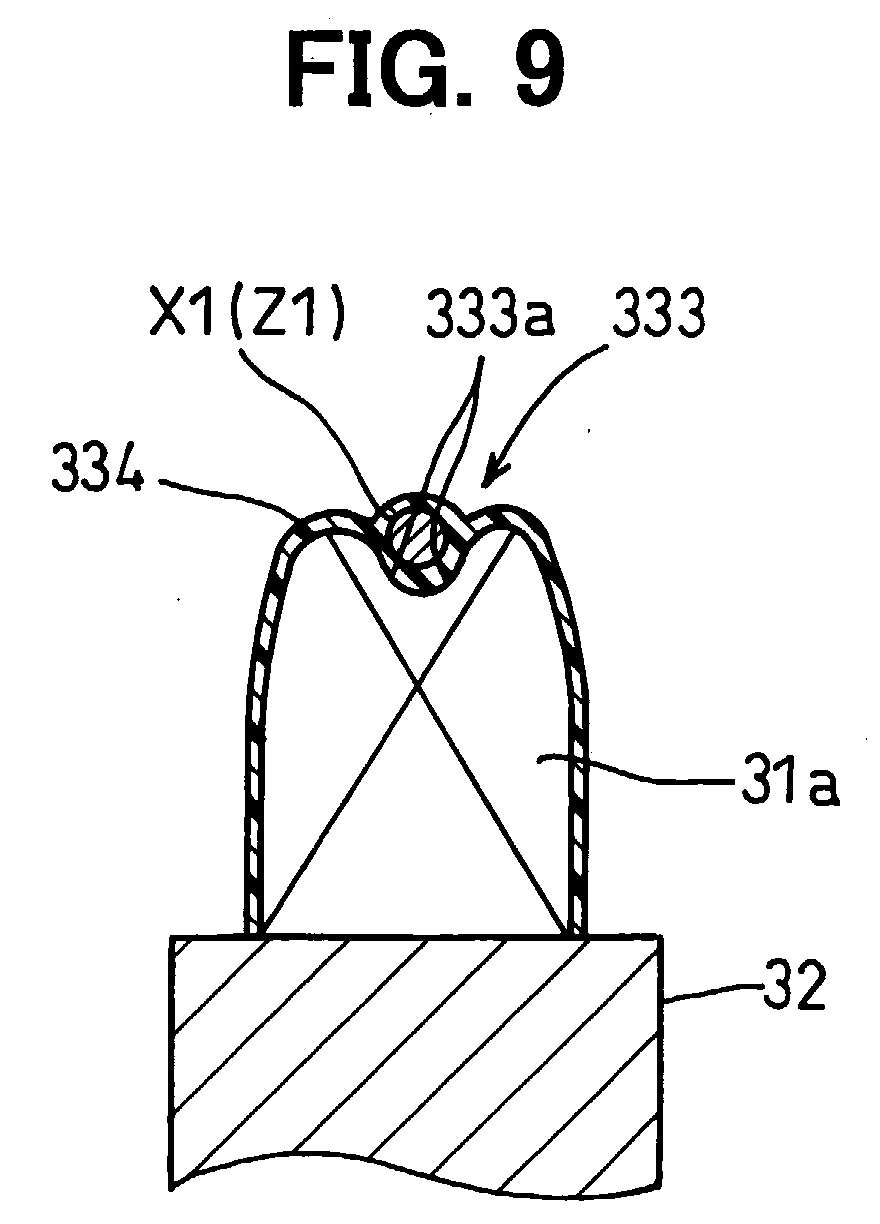
- a depressed ditch 333 is formed on and along the top portion of the rear coil end 31a.
- a bottom surface 333a of the depressed ditch 333 is formed to fit a cross-sectional shape of the lead wires X1 (or Z1).
- the cross-sectional shape of the lead wire X1 (Z1) is round. Therefore, the shape of the bottom surface 333a is formed in a round shape.
- the lead wire X1 (Z1) is disposed in the depressed ditch 333 and fixed thereto with adhesive 334.
- the adhesive 334 is made of heat-resistant resin having a high electrical insulation ability, such as epoxy-type resin or silicone-type resin.
- the depressed ditch 333 is formed on and along the circular rear coil end 31a, pressing a jig against the rear coil end 31a after the stator winding 31 and the read coil end 31a are formed.
- the depressed ditch 333 may be formed for covering only places where the lead wires X1, Z1 are disposed, or all along an entire circumference of the circular coil end 31a.
- the lead wires are disposed in the depressed ditch 333 and fixed thereto with the adhesive 334, movement of the lead wires relative to the coil end 31a is surely restricted, and the lead wires are firmly held in the depressed ditch 333. Therefore, the lead wires are not separated from the coil end 31a even when a high vibrating force is applied to the lead wires. Thus, reliability of the alternator 1 is enhanced.
- depressed portions corresponding to the depressed ditch 333 may be formed on the turning portions 331c, 332c of the individual conductor segments 33 (the large conductor segment 331 and small conductor segment 332) before the segments are inserted into the slots 35 of the stator core 32. In this manner, interferences among the phase-windings, which may be possibly caused at a time of forming the depressed ditch 333 after the coil end 31a is formed, are avoided.
- the shape of the depressed ditch 333 may be changed to a form shown in FIG. 11.
- the depressed ditch 333 is formed to fit the rectangular cross-section.
- the bottom surface 333a of the depressed ditch 333 is formed in a shape that includes two side surfaces contacting two sides of the rectangular cross-section of the lead wire. In this manner, the lead wire can be firmly held in the depressed ditch 333, avoiding any movement relative to the coil end 31a.
- the cross-sectional shape of the lead wire is not limited to the rectangular shape, it may be other polygonal shapes. In any case, the depressed ditch 333 is shaped to fit the cross-section of the lead wire.
- the depressed ditch for restricting movement of the lead wire X1 (Z1) is not formed on the coil end 31a.
- the top portion of the circular coil end 31a is deformed to have a top portion 336 that engages with a depressed groove 335 formed on the lead wire.
- the top portion 336 has a top flat surface and a pair of sloped outer surfaces 336a.
- the depressed groove 335 is formed to have a flat bottom surface and a pair of sloped inner surfaces 335a, so that the depressed groove 335 engages with the top portion 336 of the coil end 31a.
- the depressed groove 335 is formed on a wire having a round cross-section by presswork.
- both are connected to each other with the adhesive 334. In this manner, the lead wire can be firmly held on the coil end 31a. It is possible to change the shapes of the depressed groove 335 and the top portion 336 to other shapes as far as both engage with each other.
- the rear coil end 31a is formed to have two top portions and a valley 337 between two top portions.
- the valley 337 includes an inner surface 337a that engages with the lead wire X1 (Z1).
- the lead wire is disposed in the valley 337 circularly extending along the circular coil end 31a and connected to the valley 337 with the adhesive 334.
- the lead wire does not move relative to the coil end 31a because the lead wire is firmly held in the valley 337.
- the coil end 31a may be modified to a shape shown in FIG. 14.
- the coil end 31a is formed by positioning its two portions in an overlapped manner. In this case, the valley 337 is not deep, but has a sufficient depth to keep the lead wire therein.
- the present invention is not limited to the embodiments described above, but it may be variously modified.
- the lead wire is connected to and held on the rear coil end 31a in the foregoing embodiments, it is possible to hold the lead wire on the front coil end.
- the U-shaped conductor segments 33 are used for forming the stator winding 31 in the foregoing embodiments, it is possible to form the stator winding 31 by winding a continuous wire.
- the way of forming the stator winding 31 may be variously modified by changing the types of electrical connection and method of electrically connecting the segment ends.
- the present invention is also applicable to rotary electric machines other than the alternator described above.
Abstract
Description
- The present invention relates to a stator of an alternator for use in an automobile vehicle, and more particularly to such a stator having lead wires firmly held on a circular coil end of a stator winding.
- A star-connection and a delta-connection are widely used for forming a three-phase stator winding of an alternating current generator. In the star-connection, one end of each phase-winding is connected to a neutral point, and generated alternating current is outputted from the other end of each phase-winding. In the delta-connection, both ends of each phase-winding are connected to another phase-winding, forming an annular circuit as a whole, and generated alternating current is taken out from three junctions in the annular circuit.
- Lead wires connecting phase-windings are usually disposed on a coil end formed at an axial end of a stator core. An example of a conventional structure of fixing the lead wires on the coil end is disclosed in JP-A-2001-103697. An essence of the fixing structure is shown in FIG. 15 attached hereto. A
lead wire 80 led out from a phase winding is positioned on and along acircular coil end 82, which is formed at an axial end of astator core 81, and is electrically connected to another phase-winding. For fixing the position of thelead wire 80, thelead wire 80 is connected to atop portion 83 of thecoil end 82 with adhesive 84. - However, the
lead wire 80 connected to thecoil end 82 in such a conventional manner may be peeled off from thecoil end 82 due to vibration of the generator, because the lead wire is fixed only by an adhesive force of theadhesive 84. Especially, in an alternator mounted on an automotive vehicle that generates a high vibration, the lead wire has to be firmly fixed to the coil end to avoid such peeling-off. - The present invention has been made in view of the above-mentioned problem, and an object of the present invention is to provide an improved stator of an alternator, in which lead wires are firmly fixed to a coil end.
- An alternator for use in an automotive vehicle includes a stator and a rotor disposed inside the stator and rotated by an engine of the automotive vehicle. The stator is composed of a cylindrical stator core and a stator winding held in the stator core. The stator winding disposed in the cylindrical stator core extends from both axial ends of the stator core, forming circular coil ends along a circumferential axial ends of the stator core. The stator winding is composed of phase-windings, e.g., three phase-windings connected in a star-connection, a delta-connection, or the like. For forming such connection in the stator winding, lead wires led out from phase-windings are disposed on and along the circular coil end and mechanically connected thereto.
- To restrict movement of the lead wires relative to the coil end due to vibration of the alternator and to firmly hold the lead wires on the coil end, a top portion of the circular coil end is depressed, thereby forming a depressed ditch. The lead wires are held in the depressed ditch and mechanically connected thereto with adhesive. The depressed ditch is formed to fit a cross-sectional shape of the lead wires. In a case where a lead wire having a rectangular cross-section is used, the depressed ditch is formed in a shape having two sides engaging with two sides of the rectangular cross-section of the lead wire. The depressed ditch may be formed after the circular coil end is formed. In a case where the stator winding is formed by using plural U-shaped segments, a top portion of each segment may be depressed before the segments are inserted into the stator core.
- Alternatively, a depressed groove that engages with the top portion of the circular coil end may be formed on the lead wire by presswork. It is also possible to form circular peaks along the circular coil end and to form a valley between the peaks. In this case, the lead wires are disposed in the valley and firmly held therein.
- According to the present invention, since the lead wires are engaged with the coil end and firmly connected thereto, the lead wires are prevented from being separated from the coil end due to vibration during operation of the alternator.
- Other objects and features of the present invention will become more readily apparent from a better understanding of the preferred embodiments described below with reference to the following drawings.
-
- FIG. 1 is a cross-sectional view showing an entire structure of an alternator;
- FIG. 2 is a cross-sectional view showing stator slots in which conductors of U-shaped conductor segments are inserted;
- FIG. 3 is a perspective view showing a large conductor segment and a small conductor segment;
- FIG. 4 is a diagram showing a first winding in an X-phase-winding;
- FIG. 5 is a diagram showing a second winding in the X-phase-winding;
- FIG. 6 is a diagram showing the X-phase-winding in which the first and the second winding are combined;
- FIG. 7 is a diagram showing an entire stator winding, in which three phase-windings are connected to a neutral point through respective lead wires;
- FIG. 8 is a circuit diagram showing a star-connection in the stator winding;
- FIG. 9 is a schematic view showing a rear coil end having a depressed ditch for holding a lead wire therein, as a first embodiment of the present invention;
- FIG. 10 is a perspective view showing U-shaped conductor segments, each having a depressed portion formed on a turning portion;
- FIG. 11 is a schematic view showing a rear coil end having a depressed ditch for holding a lead wire therein, as a modified form of the first embodiment, the depressed ditch including two side surfaces contacting the lead wire;
- FIG. 12 is a schematic view showing a rear coil end to which a lead wire having a depressed groove is connected, as a second embodiment of the present invention;
- FIG. 13 is a schematic view showing a rear coil end that includes a valley for holding a lead wire therein, as a third embodiment of the present invention;
- FIG. 14 is a schematic view showing a rear coil end that includes a shallow valley for holding a lead wire therein, as a modified form of the third embodiment; and
- FIG. 15 is a schematic view showing a conventional form of a coil end to which a lead wire is attached.
-
- A first embodiment of the present invention will be described with reference to FIGS. 1-11. First, referring to FIG. 1, a structure of an
alternator 1 for use in an automotive vehicle will be described. Thealternator 1 includes astator 2, arotor 3, ahousing 4, arectifier 5 and other associated components. Therotor 3 is composed of ashaft 6, a Lundell-type pole core 7 fixed to theshaft 6, afield coil 8 wound on thepole core 7, andslip rings shaft 6. Aslant fan 11 is connected to a front side of thepole core 7, and acentrifugal fan 12 is connected to a rear side of thepole core 7. Apulley 20 is fixed to a theshaft 6, and therotor 3 is rotated by an engine mounted on an automobile. - The Lundell-
type pole core 7 is a known type and composed of a pair of cores, each having aboss 71 fixed to theshaft 6, adisc portion 72 and sixclaw poles 73. By coupling the pair of cores to face each other, apole core 7 having twelve claw poles is formed. Theslant fan 11 is composed of abase plate 111 connected to a front surface of thepole core 7 by welding or the like and blades each having a portion slanted relative to thebase plate 111 and an upright portion. Thecentrifugal fan 12 is composed of abase plate 121 connected to a rear surface of thepole core 7 and blades standing from thebase plate 121 with a right angle. - The
housing 4 is composed of afront housing 4a and arear housing 4b, both being connected by through-bolts 4c. Cooling air is introduced into thehousing 4 throughinlet windows 41 formed at both axial sides of thehousing 4, and the cooling air is blown out throughoutlet windows 42 formed at shoulder portions of thehousing 4. Therectifier 5 for rectifying alternating current into direct current is mounted on the rear side of thehousing 4. Thestator 2 functioning as an armature is composed of acylindrical stator core 32 having plural slots 35 (shown in FIG. 2) and a stator winding 31 formed by pluralU-shaped conductor segments 33 inserted into theslots 35. - Referring to FIGS. 2 and 3, the stator winding 31 will be described in detail. As shown in FIG. 2, conductors of the
U-shaped conductor segments 33 are inserted into theslots 35 of thestator core 32. The conductors inserted into theslots 35 are insulated from thestator core 32 by aninsulator 34.Plural slots 35, each having an opening at an inner surface of thestator core 32, are formed in thestator core 32 so that a multiphase stator winding is accommodated in theslots 35. In this particular embodiment, 36 slots for accommodating a three-phase stator winding are formed. - As shown in FIG. 3, the
conductor segments 33 include alarge conductor segment 331 and asmall conductor segment 332. Both of the large andsmall conductor segments large conductor segment 331 includes a pair ofstraight conductor portions portion 331c connecting the pair of conductor portions, and a pair of segment ends 331d and 331e. Similarly, thesmall conductor segment 332 includes a pair ofstraight conductor portions portion 332c connecting the conductor portions, and a pair of segment ends 332d and 332e. - As shown in FIG. 2, the
conductor portion 331a is positioned at an inner most position in theslot 35, and therefore theconductor portion 331a is referred to as a first layer conductor. Theconductor portion 332a is positioned next to thefirst layer conductor 331a and referred to as a second layer conductor. Theconductor portion 332b that makes a pair with theconductor portion 332a is inserted into anotherslot 35 that is one-pole pitch apart from the slot in which theconductor portion 332a is inserted and is positioned at a third layer position in that slot. Theconductor portion 332b is referred to as a third layer conductor. Theconductor portion 331b that makes a pair with theconductor portion 331a is inserted into the same slot into which theconductor portion 332b is inserted and positioned at a fourth layer position (an outermost position) in that slot. FIG. 2 shows the one slot where thefirst layer conductor 331a, thesecond layer conductor 332a, athird layer conductor 332b' (a third layer conductor of another segment), and afourth layer conductor 331b' (a fourth layer conductor of another segment) are inserted in this order. - A
rear coil end 31a (shown in FIG. 1) is formed by turningportions portion 332c of thesmall segment 332 is positioned inside each turningportion 331c of thelarge segment 331. Afront coil end 31b (shown in FIG. 1) is formed by segment ends and slanted portions connecting the segment ends and the conductor portions of plural conductor segments. Thesegment end 332d of thesmall conductor segment 332 and asegment end 331d' of alarge conductor segment 331 are electrically connected by welding, as shown in FIG. 3. Similarly, thesegment end 332e of thesmall conductor segment 332 and asegment end 331e' of anotherlarge conductor segment 331 are electrically connected by welding. The three-phase stator winding 31 is formed by electrically connecting the segment ends of the plural U-shaped conductor segments in this manner. - Referring to FIGS. 4-6, formation of an X-phase-winding will be described as a representative of three phase-windings, X, Y and Z. In these drawings, the first conductor layer is shown by a chained line with two dots, the second conductor layer with a solid line, the third conductor layer with a dotted line, and the fourth conductor layer with a chained line with one dot. The
rear coil end 31a formed by turningportions conductor segments 33 is shown at an upper side, and thefront coil end 31b is shown at a bottom side. Numbers shown along a horizontal line in these drawings are slot numbers from 1 to 36. - As shown in FIG. 4, a conductor of a
conductor segment 33 is positioned in one slot, and another conductor of the same conductor segment is positioned in another slot which is apart from the former by three slots (one-pole-pitch) . At thefront coil end 31b, a segment end of thethird layer conductor 332b disposed in one slot is connected to a segment end of thefourth layer conductor 331b disposed in another slot which is apart from the former by one-pole-pitch. A segment end of thefirst layer conductor 331a disposed in one slot is connected to a segment end of thesecond layer conductor 332a disposed in another slot which is apart from the former by one-pole-pitch. In this manner, a first winding 311 having two overlapped turns per one slot is formed. Similarly, as shown in FIG. 5, a second winding 312 having two overlapped turns per one slot is formed. - As shown in FIG. 6, one
end 33m of the first winding 311 is connected to oneend 33n of the second winding 312, thereby forming the X-phase-winding 315 having four overlapped turns per one slot. For connecting twoends ends large segment 331 and the small segment 332). - The other phase-windings, the γ-phase-winding and the Z-phase winding, are similarly formed in the slots which are apart from one phase to another phase by an electrical angle of 120 degrees. As shown in FIG. 7, one end of each phase-winding is connected to a lead wire X1, Y1 and Z1, respectively. The lead wires X1, Y1 and Z1 are connected to a
neutral point 33k. The other ends X2, Y2 and Z2 of the phase-windings are led out from the rear coil end side. As shown in FIG. 8, the stator winding 31 composed of the X-phase-winding, the Y-phase-winding and the Z-phase-winding is connected in a star connection. That is, the lead wires X1, Y1 and Z1 are connected to theneutral point 33k, and the other ends X2, Y2 and Z2 of the phase-windings are connected to respective points in therectifier 5. - A manufacturing process of the stator winding 31 will be briefly described. Plural U-shaped conductor segments including the
large conductor segments 331 and thesmall conductor segments 332 are prepared. The U-shaped conductor segments are inserted intoslots 35 from the rear side of thestator core 32, so that the conductor portions are positioned in eachslot 35 as shown in FIG. 2. That is, thefirst layer conductor 331a, thesecond layer conductor 332a, thethird layer conductor 332b' and thefourth layer conductor 331b' are positioned in this order from the inside of thestator 32. The turningportions 332c of thesmall conductor segments 332 are covered by the turningportions 331c of thelarge conductor segments 331, thereby forming therear coil end 31a. - After the conductor segments are inserted into the
slots 35, straight portions of the segments extending to the front side of thestator core 32 are bent, so that a distance between the segment ends 331d and 331e of thelarge conductor segment 331 is widened, and a distance between the segment ends 332d and 332e is narrowed. More particularly, each straight portion of thelarge conductor segment 331 is bent by 1.5 slot-pitches, and each straight portion of thesmall conductor segment 332 is bent by 1.5 slot-pitches, thereby positioning the segment ends 331d, 331e, 332d, 332e as shown in FIG. 3. All the conductor segments are bent in the same manner. Then, each pair of segment ends is electrically connected by welding. More particularly, the segment ends 331e' and 332e; and segment ends 332d and 331d' are electrically connected (refer to FIG. 3). - Now, how the lead wires led out from the phase-windings are connected and held on the rear coil end will be described. The
rear coil end 31a extending from the axial rear end of thecylindrical stator core 32 is formed in a circular shape along a circumference of the cylindrical stator core. As shown in FIG. 7, the lead wires X1, Y1 and Z1 led out from the respective phase-windings extend to the rear coil end side. The lead wires X1 and Z1 are further extended along the circularrear coil end 31a toward the lead wire Y1 and are electrically connected to the lead wire Y1. The lead wire Y1 is positioned between the lead wires X1 and Z1 so that the length of lead wires X1 and Y1 extending along the circularrear coil end 31a becomes shortest. - As shown in FIG. 9, a
depressed ditch 333 is formed on and along the top portion of therear coil end 31a. Abottom surface 333a of thedepressed ditch 333 is formed to fit a cross-sectional shape of the lead wires X1 (or Z1). In this particular embodiment shown in FIG. 9, the cross-sectional shape of the lead wire X1 (Z1) is round. Therefore, the shape of thebottom surface 333a is formed in a round shape. The lead wire X1 (Z1) is disposed in thedepressed ditch 333 and fixed thereto withadhesive 334. The adhesive 334 is made of heat-resistant resin having a high electrical insulation ability, such as epoxy-type resin or silicone-type resin. - The
depressed ditch 333 is formed on and along the circularrear coil end 31a, pressing a jig against therear coil end 31a after the stator winding 31 and the readcoil end 31a are formed. Thedepressed ditch 333 may be formed for covering only places where the lead wires X1, Z1 are disposed, or all along an entire circumference of thecircular coil end 31a. - Since the lead wires are disposed in the
depressed ditch 333 and fixed thereto with the adhesive 334, movement of the lead wires relative to thecoil end 31a is surely restricted, and the lead wires are firmly held in thedepressed ditch 333. Therefore, the lead wires are not separated from thecoil end 31a even when a high vibrating force is applied to the lead wires. Thus, reliability of thealternator 1 is enhanced. - As shown in FIG. 10, depressed portions corresponding to the
depressed ditch 333 may be formed on the turningportions large conductor segment 331 and small conductor segment 332) before the segments are inserted into theslots 35 of thestator core 32. In this manner, interferences among the phase-windings, which may be possibly caused at a time of forming thedepressed ditch 333 after thecoil end 31a is formed, are avoided. - The shape of the
depressed ditch 333 may be changed to a form shown in FIG. 11. In the case where the lead wire has a rectangular cross-section, thedepressed ditch 333 is formed to fit the rectangular cross-section. Thebottom surface 333a of thedepressed ditch 333 is formed in a shape that includes two side surfaces contacting two sides of the rectangular cross-section of the lead wire. In this manner, the lead wire can be firmly held in thedepressed ditch 333, avoiding any movement relative to thecoil end 31a. The cross-sectional shape of the lead wire is not limited to the rectangular shape, it may be other polygonal shapes. In any case, thedepressed ditch 333 is shaped to fit the cross-section of the lead wire. - A second embodiment of the present invention will be described with reference to FIG. 12. In this embodiment, the depressed ditch for restricting movement of the lead wire X1 (Z1) is not formed on the
coil end 31a. Instead, the top portion of thecircular coil end 31a is deformed to have atop portion 336 that engages with adepressed groove 335 formed on the lead wire. In this particular embodiment, thetop portion 336 has a top flat surface and a pair of sloped outer surfaces 336a. Thedepressed groove 335 is formed to have a flat bottom surface and a pair of slopedinner surfaces 335a, so that thedepressed groove 335 engages with thetop portion 336 of thecoil end 31a. Thedepressed groove 335 is formed on a wire having a round cross-section by presswork. After the lead wire X1 (Z1) is engaged with thecoil end 31a, both are connected to each other with the adhesive 334. In this manner, the lead wire can be firmly held on thecoil end 31a. It is possible to change the shapes of thedepressed groove 335 and thetop portion 336 to other shapes as far as both engage with each other. - A third embodiment of the present invention will be described with reference to FIG. 13. In this embodiment, the
rear coil end 31a is formed to have two top portions and avalley 337 between two top portions. Thevalley 337 includes aninner surface 337a that engages with the lead wire X1 (Z1). The lead wire is disposed in thevalley 337 circularly extending along thecircular coil end 31a and connected to thevalley 337 with the adhesive 334. The lead wire does not move relative to thecoil end 31a because the lead wire is firmly held in thevalley 337. Thecoil end 31a may be modified to a shape shown in FIG. 14. Thecoil end 31a is formed by positioning its two portions in an overlapped manner. In this case, thevalley 337 is not deep, but has a sufficient depth to keep the lead wire therein. - The present invention is not limited to the embodiments described above, but it may be variously modified. For example, though the lead wire is connected to and held on the
rear coil end 31a in the foregoing embodiments, it is possible to hold the lead wire on the front coil end. Though theU-shaped conductor segments 33 are used for forming the stator winding 31 in the foregoing embodiments, it is possible to form the stator winding 31 by winding a continuous wire. The way of forming the stator winding 31 may be variously modified by changing the types of electrical connection and method of electrically connecting the segment ends. The present invention is also applicable to rotary electric machines other than the alternator described above. - While the present invention has been shown and described with reference to the foregoing preferred embodiments, it will be apparent to those skilled in the art that changes in form and detail may be made therein without departing from the scope of the invention as defined in the appended claims.
Claims (5)
- A stator (2) of an alternator (1), the stator comprising:a cylindrical stator core (32);a stator winding (31) composed of phase-windings held in the stator core, the stator winding forming a circular coil end (31a) extending from an axial end of the cylindrical stator core;lead wires (X1, Z1) led out from the phase-windings and disposed along the circular coil end (31a); andmeans (333, 335, 337) for restricting movement of the lead wires relative to the circular coil end.
- The stator of an alternator as in claim 1, wherein:the restricting means is a depressed ditch (333) formed on and long the circular coil end (31a), so that the lead wires engage with the depressed ditch.
- The stator of an alternator as in claim 1, wherein:the restricting means is a depressed groove (335) formed on the lead wires (X1, Z1), so that the depressed groove engages with a top portion (336) of the coil end.
- The stator of an alternator as in claim 2, wherein:the lead wire (X1, Z1) has a substantially rectangular cross-section; andthe depressed ditch (333) includes tow side surfaces (333a) contacting two sides of the rectangular cross-section of the lead wire.
- The stator of an alternator as in claim 1, wherein:the circular coil end (31a) includes circular peaks forming a valley (337) therebetween ; andthe restricting means is the valley in which the lead wires are held.
Applications Claiming Priority (2)
| Application Number | Priority Date | Filing Date | Title |
|---|---|---|---|
| JP2002177075A JP2004023916A (en) | 2002-06-18 | 2002-06-18 | Stator of rotary electric machine |
| JP2002177075 | 2002-06-18 |
Publications (3)
| Publication Number | Publication Date |
|---|---|
| EP1376823A2 true EP1376823A2 (en) | 2004-01-02 |
| EP1376823A3 EP1376823A3 (en) | 2004-08-18 |
| EP1376823B1 EP1376823B1 (en) | 2008-08-06 |
Family
ID=29717465
Family Applications (1)
| Application Number | Title | Priority Date | Filing Date |
|---|---|---|---|
| EP03012054A Expired - Fee Related EP1376823B1 (en) | 2002-06-18 | 2003-05-28 | Stator winding coil ends fastening device for an alternator |
Country Status (6)
| Country | Link |
|---|---|
| US (1) | US6888281B2 (en) |
| EP (1) | EP1376823B1 (en) |
| JP (1) | JP2004023916A (en) |
| KR (1) | KR100557396B1 (en) |
| CN (1) | CN1266819C (en) |
| DE (1) | DE60322628D1 (en) |
Cited By (1)
| Publication number | Priority date | Publication date | Assignee | Title |
|---|---|---|---|---|
| US6888281B2 (en) * | 2002-06-18 | 2005-05-03 | Denso Corporation | Stator of alternator having lead wires firmly held on circular coil end of stator winding |
Families Citing this family (17)
| Publication number | Priority date | Publication date | Assignee | Title |
|---|---|---|---|---|
| JP4596127B2 (en) * | 2004-06-02 | 2010-12-08 | 株式会社デンソー | Rotating electric machine stator |
| CN100581048C (en) * | 2005-03-31 | 2010-01-13 | 阿尔斯通技术有限公司 | High-phase order generator |
| JP4476199B2 (en) | 2005-09-12 | 2010-06-09 | 三菱電機株式会社 | Rotating electric machine stator |
| JP5062651B2 (en) * | 2005-10-11 | 2012-10-31 | 三菱電機株式会社 | Rotating electric machine stator |
| US8134272B2 (en) * | 2006-07-26 | 2012-03-13 | Mitsubishi Electric Corporation | Dynamoelectric machine |
| JP5158477B2 (en) * | 2007-08-29 | 2013-03-06 | 日本精工株式会社 | Electric motor and electric power steering apparatus |
| JP4600487B2 (en) * | 2008-02-13 | 2010-12-15 | 株式会社デンソー | Method for manufacturing circumferentially developed stator coil and motor using this circumferentially developed stator coil |
| CN102077444B (en) | 2008-07-01 | 2013-10-30 | 三菱电机株式会社 | Stator for rotary electric machine for vehicle |
| JP5466384B2 (en) * | 2008-08-19 | 2014-04-09 | 株式会社ミツバ | Magnet generator |
| JP5432806B2 (en) * | 2010-04-06 | 2014-03-05 | 株式会社デンソー | Rotating electric machine stator and rotating electric machine |
| US8916999B2 (en) * | 2011-01-01 | 2014-12-23 | Asmo Co., Ltd. | Motors containing segment conductor coils |
| US20140111055A1 (en) * | 2012-10-23 | 2014-04-24 | Remy Technologies, L.L.C. | Conductor with divot for improved form factor |
| WO2015083623A1 (en) * | 2013-12-02 | 2015-06-11 | デンソートリム株式会社 | Magnet-type electric generator |
| US10715001B2 (en) * | 2017-06-28 | 2020-07-14 | Hitachi Automotive Systems, Ltd. | Dynamo-Electric Machine |
| WO2020054467A1 (en) * | 2018-09-14 | 2020-03-19 | パナソニックIpマネジメント株式会社 | Motor, and coil used for same |
| US11632006B2 (en) | 2020-04-27 | 2023-04-18 | Honeywell International Inc. | Stator coil for high power density and efficiency electric machines |
| CN117254620B (en) * | 2023-09-06 | 2024-04-02 | 小米汽车科技有限公司 | Motor end winding, stator assembly, motor and vehicle |
Citations (5)
| Publication number | Priority date | Publication date | Assignee | Title |
|---|---|---|---|---|
| GB705650A (en) * | 1951-10-05 | 1954-03-17 | Gen Electric | Improvements in and relating to dynamoelectric machines |
| US4318022A (en) * | 1977-10-25 | 1982-03-02 | General Electric Company | End turn and terminal support for a stator assembly |
| JPS63294242A (en) * | 1987-05-26 | 1988-11-30 | Mitsubishi Electric Corp | Stator of ac generator for vehicle |
| US6204586B1 (en) * | 1998-11-25 | 2001-03-20 | Denso Corporation | Stator arrangement of vehicle AC generator |
| EP1143596A2 (en) * | 2000-04-03 | 2001-10-10 | Mitsubishi Denki Kabushiki Kaisha | Winding connections for the stator of an alternator |
Family Cites Families (17)
| Publication number | Priority date | Publication date | Assignee | Title |
|---|---|---|---|---|
| US3631279A (en) * | 1970-02-16 | 1971-12-28 | Reliance Electric Co The | Dynamoelectric machine blocking means |
| SU792483A1 (en) * | 1977-12-22 | 1980-12-30 | Предприятие П/Я А-7376 | Electric machine stator |
| JPS54115704A (en) * | 1978-03-01 | 1979-09-08 | Hitachi Ltd | Supporting construction of revolving electrical machinery stator winding ends |
| JPS5526012A (en) * | 1978-08-11 | 1980-02-25 | Hitachi Ltd | Stator for motor |
| JPS5615143A (en) * | 1979-07-18 | 1981-02-13 | Hitachi Ltd | Device for supporting stator coil of rotary electric machine |
| AU567527B2 (en) * | 1982-12-20 | 1987-11-26 | Mitsubishi Denki Kabushiki Kaisha | Coil insulating method |
| DE3817912C3 (en) | 1987-05-26 | 1996-06-13 | Mitsubishi Electric Corp | Stator of a three-phase machine arranged in motor vehicles |
| JP3598581B2 (en) * | 1995-05-19 | 2004-12-08 | 株式会社デンソー | Rotor coil of generator and method of manufacturing the same |
| US6043584A (en) * | 1998-04-22 | 2000-03-28 | Reliance Electric Industrial Company | End turn phase insulator and method of using same |
| JP3256695B2 (en) * | 1999-12-24 | 2002-02-12 | 三菱電機株式会社 | Alternator stator |
| JP3347115B2 (en) * | 1999-12-20 | 2002-11-20 | 三菱電機株式会社 | AC generator |
| JP3400776B2 (en) * | 1999-12-14 | 2003-04-28 | 三菱電機株式会社 | AC generator |
| JP3707606B2 (en) * | 2000-02-07 | 2005-10-19 | 三菱電機株式会社 | Winding assembly of rotating electrical machine, manufacturing method thereof, and stator of rotating electrical machine using the winding assembly |
| JP3767789B2 (en) * | 2000-02-21 | 2006-04-19 | 三菱電機株式会社 | Alternator stator |
| JP3650303B2 (en) * | 2000-02-29 | 2005-05-18 | 三菱電機株式会社 | AC generator |
| JP4187914B2 (en) * | 2000-08-29 | 2008-11-26 | 三菱電機株式会社 | Rotating electric machine stator |
| JP2004023916A (en) * | 2002-06-18 | 2004-01-22 | Denso Corp | Stator of rotary electric machine |
-
2002
- 2002-06-18 JP JP2002177075A patent/JP2004023916A/en active Pending
-
2003
- 2003-05-28 EP EP03012054A patent/EP1376823B1/en not_active Expired - Fee Related
- 2003-05-28 DE DE60322628T patent/DE60322628D1/en not_active Expired - Lifetime
- 2003-05-30 US US10/448,085 patent/US6888281B2/en not_active Expired - Lifetime
- 2003-06-14 KR KR1020030038496A patent/KR100557396B1/en not_active IP Right Cessation
- 2003-06-18 CN CNB031491839A patent/CN1266819C/en not_active Expired - Fee Related
Patent Citations (5)
| Publication number | Priority date | Publication date | Assignee | Title |
|---|---|---|---|---|
| GB705650A (en) * | 1951-10-05 | 1954-03-17 | Gen Electric | Improvements in and relating to dynamoelectric machines |
| US4318022A (en) * | 1977-10-25 | 1982-03-02 | General Electric Company | End turn and terminal support for a stator assembly |
| JPS63294242A (en) * | 1987-05-26 | 1988-11-30 | Mitsubishi Electric Corp | Stator of ac generator for vehicle |
| US6204586B1 (en) * | 1998-11-25 | 2001-03-20 | Denso Corporation | Stator arrangement of vehicle AC generator |
| EP1143596A2 (en) * | 2000-04-03 | 2001-10-10 | Mitsubishi Denki Kabushiki Kaisha | Winding connections for the stator of an alternator |
Non-Patent Citations (1)
| Title |
|---|
| PATENT ABSTRACTS OF JAPAN vol. 0131, no. 26 (E-734), 28 March 1989 (1989-03-28) -& JP 63 294242 A (MITSUBISHI ELECTRIC CORP), 30 November 1988 (1988-11-30) * |
Cited By (1)
| Publication number | Priority date | Publication date | Assignee | Title |
|---|---|---|---|---|
| US6888281B2 (en) * | 2002-06-18 | 2005-05-03 | Denso Corporation | Stator of alternator having lead wires firmly held on circular coil end of stator winding |
Also Published As
| Publication number | Publication date |
|---|---|
| DE60322628D1 (en) | 2008-09-18 |
| EP1376823A3 (en) | 2004-08-18 |
| KR20040002554A (en) | 2004-01-07 |
| US6888281B2 (en) | 2005-05-03 |
| CN1266819C (en) | 2006-07-26 |
| KR100557396B1 (en) | 2006-03-06 |
| EP1376823B1 (en) | 2008-08-06 |
| JP2004023916A (en) | 2004-01-22 |
| CN1471218A (en) | 2004-01-28 |
| US20030230953A1 (en) | 2003-12-18 |
Similar Documents
| Publication | Publication Date | Title |
|---|---|---|
| EP1376823B1 (en) | Stator winding coil ends fastening device for an alternator | |
| EP1369979B1 (en) | Method of manufacturing stator winding of rotary electric machine | |
| EP1120884B1 (en) | Alternator | |
| EP1005137B1 (en) | Stator of AC-generator and method of manufacturing the same | |
| EP1294076B1 (en) | Stator for an alternator and method for the manufacture thereof | |
| EP1143596B1 (en) | Winding connections for the stator of an alternator | |
| EP2045896B1 (en) | Dynamo-electric machine | |
| EP1347559B1 (en) | Manufacturing method for a wound stator of a rotary electric machine | |
| JPH11346448A (en) | Stator of ac generator for vehicle | |
| US20020175589A1 (en) | Automotive alternator | |
| JP3303809B2 (en) | Stator of vehicle alternator | |
| US20130214634A1 (en) | Automotive rotary electric machine and stator manufacturing method that is used therefor | |
| EP1176695B1 (en) | Coil ends of a dynamo-electric machine | |
| US6459187B1 (en) | Alternator | |
| US6911758B2 (en) | Stator for a rotary electric machine | |
| EP1341292B1 (en) | Method of manufacturing the winding of an electric machine | |
| EP1120883B1 (en) | Alternator | |
| JP2004104996A (en) | Stator of rotary electric machine | |
| US6882067B2 (en) | Stator for a dynamoelectric machine | |
| EP1109293B1 (en) | Alternator and method of manufacture therefor | |
| US7342340B2 (en) | Alternator with identical conductor segments | |
| EP1109295A2 (en) | Winding heads for the stator of an alternator |
Legal Events
| Date | Code | Title | Description |
|---|---|---|---|
| PUAI | Public reference made under article 153(3) epc to a published international application that has entered the european phase |
Free format text: ORIGINAL CODE: 0009012 |
|
| AK | Designated contracting states |
Kind code of ref document: A2 Designated state(s): AT BE BG CH CY CZ DE DK EE ES FI FR GB GR HU IE IT LI LU MC NL PT RO SE SI SK TR |
|
| AX | Request for extension of the european patent |
Extension state: AL LT LV MK |
|
| PUAL | Search report despatched |
Free format text: ORIGINAL CODE: 0009013 |
|
| AK | Designated contracting states |
Kind code of ref document: A3 Designated state(s): AT BE BG CH CY CZ DE DK EE ES FI FR GB GR HU IE IT LI LU MC NL PT RO SE SI SK TR |
|
| AX | Request for extension of the european patent |
Extension state: AL LT LV MK |
|
| 17P | Request for examination filed |
Effective date: 20041026 |
|
| AKX | Designation fees paid |
Designated state(s): DE FR GB IT |
|
| RBV | Designated contracting states (corrected) |
Designated state(s): DE FR GB IT |
|
| GRAP | Despatch of communication of intention to grant a patent |
Free format text: ORIGINAL CODE: EPIDOSNIGR1 |
|
| GRAS | Grant fee paid |
Free format text: ORIGINAL CODE: EPIDOSNIGR3 |
|
| GRAA | (expected) grant |
Free format text: ORIGINAL CODE: 0009210 |
|
| AK | Designated contracting states |
Kind code of ref document: B1 Designated state(s): DE FR GB IT |
|
| REG | Reference to a national code |
Ref country code: GB Ref legal event code: FG4D |
|
| REF | Corresponds to: |
Ref document number: 60322628 Country of ref document: DE Date of ref document: 20080918 Kind code of ref document: P |
|
| PLBE | No opposition filed within time limit |
Free format text: ORIGINAL CODE: 0009261 |
|
| STAA | Information on the status of an ep patent application or granted ep patent |
Free format text: STATUS: NO OPPOSITION FILED WITHIN TIME LIMIT |
|
| 26N | No opposition filed |
Effective date: 20090507 |
|
| PGFP | Annual fee paid to national office [announced via postgrant information from national office to epo] |
Ref country code: GB Payment date: 20140521 Year of fee payment: 12 |
|
| PGFP | Annual fee paid to national office [announced via postgrant information from national office to epo] |
Ref country code: IT Payment date: 20140530 Year of fee payment: 12 Ref country code: DE Payment date: 20140521 Year of fee payment: 12 |
|
| REG | Reference to a national code |
Ref country code: DE Ref legal event code: R119 Ref document number: 60322628 Country of ref document: DE |
|
| GBPC | Gb: european patent ceased through non-payment of renewal fee |
Effective date: 20150528 |
|
| PG25 | Lapsed in a contracting state [announced via postgrant information from national office to epo] |
Ref country code: IT Free format text: LAPSE BECAUSE OF NON-PAYMENT OF DUE FEES Effective date: 20150528 |
|
| PG25 | Lapsed in a contracting state [announced via postgrant information from national office to epo] |
Ref country code: GB Free format text: LAPSE BECAUSE OF NON-PAYMENT OF DUE FEES Effective date: 20150528 Ref country code: DE Free format text: LAPSE BECAUSE OF NON-PAYMENT OF DUE FEES Effective date: 20151201 |
|
| REG | Reference to a national code |
Ref country code: FR Ref legal event code: PLFP Year of fee payment: 14 |
|
| REG | Reference to a national code |
Ref country code: FR Ref legal event code: PLFP Year of fee payment: 15 |
|
| PGFP | Annual fee paid to national office [announced via postgrant information from national office to epo] |
Ref country code: FR Payment date: 20170523 Year of fee payment: 15 |
|
| PG25 | Lapsed in a contracting state [announced via postgrant information from national office to epo] |
Ref country code: FR Free format text: LAPSE BECAUSE OF NON-PAYMENT OF DUE FEES Effective date: 20180531 |