EP1376108A2 - Dispositif d'évaluation d'un cristal - Google Patents
Dispositif d'évaluation d'un cristal Download PDFInfo
- Publication number
- EP1376108A2 EP1376108A2 EP03013728A EP03013728A EP1376108A2 EP 1376108 A2 EP1376108 A2 EP 1376108A2 EP 03013728 A EP03013728 A EP 03013728A EP 03013728 A EP03013728 A EP 03013728A EP 1376108 A2 EP1376108 A2 EP 1376108A2
- Authority
- EP
- European Patent Office
- Prior art keywords
- sample
- crystal
- ray
- rays
- evaluating device
- Prior art date
- Legal status (The legal status is an assumption and is not a legal conclusion. Google has not performed a legal analysis and makes no representation as to the accuracy of the status listed.)
- Granted
Links
Images
Classifications
-
- G—PHYSICS
- G01—MEASURING; TESTING
- G01N—INVESTIGATING OR ANALYSING MATERIALS BY DETERMINING THEIR CHEMICAL OR PHYSICAL PROPERTIES
- G01N23/00—Investigating or analysing materials by the use of wave or particle radiation, e.g. X-rays or neutrons, not covered by groups G01N3/00 – G01N17/00, G01N21/00 or G01N22/00
- G01N23/20—Investigating or analysing materials by the use of wave or particle radiation, e.g. X-rays or neutrons, not covered by groups G01N3/00 – G01N17/00, G01N21/00 or G01N22/00 by using diffraction of the radiation by the materials, e.g. for investigating crystal structure; by using scattering of the radiation by the materials, e.g. for investigating non-crystalline materials; by using reflection of the radiation by the materials
Definitions
- the present invention relates to a crystal evaluating device for measuring and evaluating the crystal quality of crystal samples by using a diffraction phenomenon of X-rays, and particularly to a crystal evaluating device suitable for crystal evaluation of proteins.
- a target protein is first crystallized in solution to achieve a crystal particle of the protein, and then the crystal particle of the protein thus achieved is inserted into a glass tubule called as a capillary.
- the capillary having the crystal particle of the protein mounted therein is sealed, and then mounted in an X-ray diffraction apparatus.
- the crystal particle of the protein is sealingly inserted into the capillary by a manual work using a Pasteur pipette, so that the sealing work is cumbersome and needs much time.
- it is also required to carry out the mount work of mounting the capillary in the X-ray diffraction apparatus every time one measuring operation is finished. Accordingly, the conventional protein crystal structure analysis has been unsuitable for such a case that many crystal samples are required to be quickly measured and evaluated.
- the proteins constituting the human body contain fifty thousands to one hundred thousands kinds of proteins, and it has been an urgent problem in the recent structural biology to clarify the structures of these many proteins in short term.
- the present invention has been implemented in the foregoing situation, and has an object to provide a crystal evaluating device that can quickly perform X-ray diffraction measurements on many crystal samples and also perform crystal structure analysis and evaluation with high reliability.
- a crystal evaluating device comprising:
- a crystallization plate having plural recess portions in which protein crystals are grown (generated) is used as a sample holder, and it is directly mounted on the sample stage and subjected to the X-ray diffraction measurement.
- the crystallization plate is originally used as an instrument for crystallizing proteins. However, when the crystallization plate is directly used as a sample holder, crystal particles generated on the crystallization plate is not needed to be individually transferred into capillaries one by one, and the time needed for the measurement work can be shortened.
- the X-ray irradiating means and the X-ray detecting means are fixed to the rotational arm, and the rotational arm can be freely rotated by any angle with the rotational driving mechanism. Therefore, the integrated intensities of the diffracted X-rays from the crystal sample can be determined without rotating the sample holder.
- the integrated intensities of the diffracted X-rays are determined by irradiating X-rays to a crystal being measured from various angles to detect the intensities of the diffracted X-rays and then integrating the intensity data thus detected.
- the integrated intensities of the diffracted X-rays are detected and determined by rotating a capillary containing a crystal sample mounted therein.
- reflected X-rays from a crystal which may induce diffraction to the X-rays is distributed in a spherical form in a reciprocal lattice space (diffraction space).
- the peak intensities (diffraction spots) of the reflected X-rays are distributed in a spherical form (i.e., distributed three-dimensionally) in a reciprocal lattice space.
- the peak intensity (diffraction spot) of the diffracted X-rays detected at a fixed position with respect to the crystal is achieved by observing only a cross-section through which the reflection X-rays distributed in the spherical form are passed, that is, the peak intensity of the diffracted X-rays detected at a fixed position merely corresponds to the peak intensity of the reflected X-rays which is achieved at a position on a plane intersecting to the spherical distribution of the reflected X-rays.
- the peak intensity (diffraction spot) thus detected is merely one of several hundreds to several thousands of peak intensities (diffraction spots) needed for the structure analysis of the crystal (i.e., needed to determine a molecular structure).
- the crystal evaluating device is designed so that the X-ray irradiating means and the X-ray detecting means are rotated with respect to the sample holder. That is, the sample holder is not rotated. Therefore, peak intensities (diffraction spots) can be detected on plural cross sections (planes) for the diffracted X-rays from the crystal which is distributed in a spherical form, and then the integrated intensities thereof can be calculated. As a result, the crystal structure can be analyzed and evaluated with high reliability on the basis of the integrated intensities of diffracted X-rays thus detected.
- the sample stage may be constructed by an X-Y table on which a sample holder is controlled to be movable in two perpendicular directions on the horizontal plane. This construction enables plural crystal samples mounted in the sample holder to be successively positioned onto a measurement line of X-rays by using the X-Y table, so that the workability can be further enhanced.
- the sample stage may be designed so that the sample holder is controlled to be further movable in the up-and-down direction.
- the crystal samples mounted in the sample holder are preferably positioned onto the rotational axis of the X-ray irradiating means and the X-ray detecting means.
- the positioning of the crystal samples with respect to the rotational axis described above can be implemented by controlling the movement of the sample holder in the two perpendicular directions on the horizontal plane and in the up-and-down direction.
- the X-ray detecting means is constructed by a two-dimensional X-ray detector for detecting diffracted X-rays from a crystal sample on a plane.
- the two-dimensional X-ray detector can collectively detect diffracted X-rays radially-reflected from a crystal sample, and thus the measurement time can be dramatically shortened. According to the two-dimensional X-ray detector, the peak intensities of diffracted X-rays reflected radially from a crystal sample are detected as diffraction spots.
- An imaging plate or CCD Charge Coupled Device
- CCD Charge Coupled Device
- the crystal evaluating device may be further equipped with a detecting position adjusting mechanism for making the X-ray detector means approach to or get away from the sample holder disposed at the sample mount portion.
- the detecting position adjusting mechanism is particularly effective to a case where the two-dimensional X-ray detector is used.
- the diffraction spots of X-rays radially reflected from crystal sample can be detected in a wide angular range.
- the diffraction spots of X-rays radially reflected from the crystal sample may be detected while overlapped with one another.
- the distance between the crystal sample and the X-ray detecting means is suitably adjusted by the detecting position adjusting mechanism to thereby achieve proper detection data.
- the detecting position adjusting mechanism may be designed so that the X-ray detecting means is controlled to be movable in parallel to the sample holder disposed at the sample mount portion, whereby the detection range of diffracted X-rays radially reflected from the crystal sample can be arbitrarily changed.
- the X-ray irradiating means may be constructed by an X-ray source for generating X-rays, and an X-ray optical system for making the X-rays thus generated monochromatic and then guiding the monochromatic X-rays to the crystal sample in the sample mount portion.
- the crystal evaluating device may be equipped with image forming means for detecting the position of the crystal sample in the sample holder and picking up images of the crystal sample.
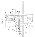
- Fig. 1 is a diagram showing a crystal evaluating device according to an embodiment of the present invention.
- the crystal evaluating device is equipped with a sample stage 10, an X-ray irradiating unit 20 (X-ray irradiating means) and an X-ray detector 30 (X-ray detecting means).
- the sample stage 10 is mounted on the main body 1 of the crystal evaluating device.
- the sample stage 10 comprises an X-Y-Z table which is designed to be movable three dimensionally, that is, in two perpendicular directions (X,Y directions in Fig. 1) on the horizontal plane and in a vertical (up-and-down) direction (Z direction in Fig. 1). Furthermore, a sample mount portion 11 for allowing a sample holder 40 to be disposed in a horizontal position is equipped on the upper surface of the sample stage 10.
- An opening (not shown) through which X-rays irradiated from the lower side of the sample mount portion 11 is transmitted is formed in the bottom surface of the sample mount portion 11.
- a holder fixing mechanism 12 for fixing the sample holder 40 to the sample mount portion 11 is equipped to the sample stage 10.
- the holder fixing mechanism 12 may be equipped with a fixing pin which is driven to be protruded and retracted by an actuator, for example.
- the sample holder 40 is fixed under pressure by the fixing pin which is protruded and retracted by the actuator.
- a generally-known crystallization plate may be used as the sample holder 40.
- the crystallization plate may be formed of material having permeability to X-rays such as polyimide or the like.
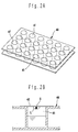
- Fig. 2A is a perspective view of the crystallization plate used as the sample holder 40. As shown in Fig. 2A, many recess portions 41 are formed in the sample holder 40 (crystallization plate), and crystals of proteins are grown and generated in these recess portions 41. Various methods such as a vapor diffusion method, etc. are known as a method of generating (growing) protein crystals by using the crystallization plate as described above.
- Fig. 2B is a schematic diagram showing the state that a crystal particle (crystal sample S) of protein is generated by the vapor diffusion method, and the protein crystal particle (crystal sample S) is grown in a drop of solution L disposed on the lower surface of a cover plate 42.
- the protein crystal particles may be individually grown in the respective recess portions 41 of the sample holder 40 under different crystal growth conditions respectively, or crystal particles of different kinds of proteins may be individually grown in the respective recess portions 41.
- the crystal evaluating device of this embodiment by directly mounting the sample holder (the crystallization plate) 40 on the sample stage 10, plural crystal samples S formed in the respective recess portions 41 of the sample holder 40 can be automatically and sequentially measured and evaluated.
- the mount and sealing work of transferring each crystal sample S from a crystal-growing portion into a capillary and then sealing the capillary so that the workability can be more remarkably enhanced.
- the X-ray irradiating unit 20 is equipped with an X-ray source 21 and an X-ray optical system 22, and an X-ray generator for laboratories is used as the X-ray generator 21.
- the X-ray generator for laboratories contains an electron gun for emitting electrons and a target against which the electrons emitted from the electron gun impinge to generate X-rays.
- the X-rays thus generated are directed to the sample holder 40.
- the X-ray generator as described above is different from large-scale X-ray generating facilities for generating radiation light and it is remarkably small in dimension and remarkably light in weight. Therefore, such an X-ray generator can be rotated while mounted on a rotational arm as described later.
- the X-ray optical system 22 functions to select X-rays having only a special wavelength (i.e., making the X-rays generated in the X-ray source 21 monochromatic), converging the monochromatic X-rays to the sample mount portion 11 on the sample stage 10, etc.
- the X-ray optical system 22 is constructed by combining various optical equipment such as a cone focal mirror, a collimator, etc.
- a two-dimensional X-ray detector is used as the X-ray detector 30.
- this embodiment uses CCD (Charge Coupled Device) as the X-ray detector 30.
- CCD Charge Coupled Device
- CCD is designed to detect diffracted X-rays from each crystal sample S on a plane, and it converts the intensities of the diffracted X-rays thus detected to electrical signals, and outputs the electrical signals to a data processing computer (not shown).
- the X-ray irradiating unit 20 and the X-ray detector 30 are respectively mounted on the rotational arm 50.
- the rotational arm 50 may be designed in any shape. For example, it may be designed in a planar or rod-like shape.
- the X-ray irradiating unit 20 is mounted at one end of the rotational arm 50, and the X-ray detector 30 is mounted on the other end portion thereof so as to confront the X-ray irradiating unit 20.
- the center portion of the rotational arm 50 is fixed to the rotating shaft 51a of a rotational driving mechanism 51 for rotating the rotational arm 50, and the rotational arm 50 is allowed to be rotated around the rotating shaft 51a by any angle by actuating the rotational driving mechanism 51.
- the center line O of the rotating shaft 51a of the rotational driving mechanism 51 is disposed in a substantially horizontal position, and the optical axis of the X-rays irradiated from the X-ray irradiating unit 20 is adjusted to cross the center axis O of the rotating shaft 51a.
- the rotational driving mechanism 51 comprises a driving motor such a stepping motor or the like whose rotational angle can be controlled with high precision, and a gear mechanism for transmitting the rotational force of the driving motor to the rotating shaft, for example.
- the rotational angle of the driving motor is controlled by a control computer (not shown). It is preferable that the rotational angle can be freely controlled in each of both the clockwise and counterclockwise (positive and negative) directions indicated by arrows in the angular range of about 45 degrees (i.e., within ⁇ 45°).
- the X-ray irradiating unit 20 mounted on the rotational arm 50 is disposed below the sample stage 10, and also the X-ray detector 30 mounted on the rotational arm 50 is disposed above the sample stage 10 as shown in Fig. 1.
- the crystal sample S generated in the sample holder on the sample stage 10 is irradiated with X-rays from the lower side by the X-ray irradiating unit 20, and the diffracted X-rays reflected from the crystal sample S are detected by the X-ray detector 30 disposed above the sample holder 40.
- the X-ray irradiating unit 20 and the X-ray detector 30 may be disposed in the opposite arrangement to that described above. That is, the X-ray irradiating unit 20 may be disposed above the sample stage 10 while the X-ray detector 30 is disposed below the X-ray detector 30.
- the X-ray detector 30 is equipped with a detecting position adjustment mechanism 31 for freely moving the X-ray detector 30 in the radial direction with respect to the rotation of the rotational arm 50 (i.e., in the direction indicated by an arrow a in Fig. 1) and also in a direction parallel to the sample stage 10 (i.e., in the direction indicated by an arrow b in Fig. 1).
- the detecting position adjustment mechanism 31 comprises at least one first guide rail 32 disposed on the rotational arm 50 so as to extend in the radial direction (elongated direction) of the rotational arm 50, a first movable table 33 movable along the first guide rail(s) 32, at least one second guide rail 34 extending in the direction indicated by the arrow B from the movable table 33, a second movable table (not shown) movable along the second guide rail(s) 34, and a driving motor (not shown) for moving each movable table.
- the X-ray detector 30 is fixed to the second movable table.
- the crystal evaluating device of this embodiment is equipped with an image pickup camera (image forming means) for checking the position of the crystal sample S under measurement in the sample holder 40.
- the image pickup camera is disposed in the main body 1 of the crystal evaluating device like the sample stage 10, and it comprises a telescope for viewing the crystal sample S under measurement in the sample holder 40 from a remote place while magnifying the pictures of the crystal sample S, a reflection mirror 62 for reflecting the pictures of the crystal sample S in the sample holder 40 to the telescope 61, and CCD 63 for picking up the pictures of the crystal sample S which are enlarged by the telescope 61.
- the image pickup camera comprising the reflection mirror 62, the telescope 61 and CCD 63 is movably mounted in the main body 1 of the device so as to approach to or get away from the sample holder 40 on the sample stage 10.
- the image pickup camera is kept to be retracted at a retract position away from the sample holder 40.
- the pictures of the crystal sample S picked up by CCD 63 are subjected to image processing and then displayed on a monitor.
- the control computer recognizes the position of the crystal sample S under measurement on the basis of the image pickup position of CCD 63, and controls the detecting position adjustment mechanism 31 and the rotational driving mechanism 51.
- the crystal evaluating device thus constructed can measure the crystal sample S under measurement through the following process.
- the sample holder 40 is mounted on the sample stage 10. This mount operation may be automatically carried out by using a carry robot disposed aside the crystal evaluating device. Subsequently, any crystal sample S generated in the sample holder 40 is positioned with respect to the optical axis of X-rays radiated from the X-ray irradiating unit 20. This positioning operation is carried out while adjusting the movement of the sample stage 10 in the X, Y directions.
- the control computer controls the movement of the sample stage 10 in the X, Y directions on the basis of the detection result to automatically position the crystal sample S.
- the position of the crystal sample S when the position of the crystal sample S is not detected in advance or when the position of the crystal sample S in the sample holder 40 is moved due to vibration during feeding or the like, the position of the crystal sample S can be checked by the image pickup camera to position the crystal sample under measurement again.
- the crystal sample S under measurement must be always located on the optical axis of the X-rays irradiated from the X-ray irradiating unit 20. Therefore, the crystal sample S is required to be positioned onto the center line O of the rotating shaft 51a. This positioning operation of the crystal sample S onto the center line O is carried out by adjusting the movement of the sample stage 10 in the Z direction.
- the distance between the crystal sample S and the X-ray detector 30 may be adjusted as occasion demands. As described above, as the X-ray detector 30 is approached to the crystal sample S, the diffraction spots (intensities) of the X-rays radially-reflected from the crystal sample S can be detected in a wider angular range. However, in the case where the reciprocal lattice density of the crystal sample is high, as the X-ray detector 30 is approached to the crystal sample S, there is a risk that the diffraction spots of the X-rays radially-reflected from the crystal sample S are detected while more remarkably overlapped with one another.
- the movement of the X-ray detector 30 in the direction of the arrow a in Fig. 1 is adjusted by the detecting position adjusting mechanism 31 so as to suitably adjust the distance between the crystal sample S and the X-ray detector 30, whereby proper detection data can be achieved.
- the movement of the X-ray detector 30 in the direction of the arrow b in Fig. 1 is adjusted by the detecting position adjusting mechanism 31, whereby the detection range of the diffracted X-rays radially-reflected from the crystal sample S can be changed.
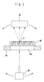
- the X-rays are radially irradiated from the X-ray irradiating unit 20 to carry out the X-ray diffraction measurement.
- the X-rays irradiated from the X-ray irradiating unit 20 are incident from the lower side to a crystal sample S under measurement in the sample holder 40.
- the sample stage 10 has the opening 10a formed therein, and the sample holder 40 is formed of the material having permeability to X-rays . Therefore, the X-rays are transmitted through these elements and irradiated to the crystal sample S under measurement.
- the X-rays incident to the crystal sample S are radially diffracted (reflected), and the diffracted X-rays are detected by the X-ray detector 30.
- the data processing computer (not shown) carries out the crystal evaluation and the crystal structure analysis on the basis of the intensity data of the diffracted X-rays thus detected.
- the rotational arm 50 is rotated by the rotational driving mechanism 51 to adjust the angles of the X-ray irradiating unit 20 and the X-ray detector 30 with respect to the lattice plane of the crystal sample S, that is, adjusting the intersecting angle between the optical axis of the X-rays irradiated from the X-ray irradiating unit 20 and the lattice plane, and the X-ray diffraction measurement described above is repeated.
- the integrated intensities of the diffracted X-rays for the crystal sample S can be determined without rotating the sample holder 40, and further the crystal structure analysis can be implemented on the basis of the integrated intensities with high reliability.
- the sample holder is not limited to the crystallization plate, and any member may be used insofar as it has permeability to X-rays .
- the number of crystal samples S generated in the sample holder 40 may be one or more.
- the crystal evaluating device of the present invention may be applied to not only the crystal evaluation of proteins, but also the crystal evaluation of low molecules, etc.
- the X-ray diffraction measurements on many crystal samples can be completely automatically and quickly performed, and also the crystal structure analysis and evaluation can be performed with high reliability.
Landscapes
- Chemical & Material Sciences (AREA)
- Crystallography & Structural Chemistry (AREA)
- Physics & Mathematics (AREA)
- Health & Medical Sciences (AREA)
- Life Sciences & Earth Sciences (AREA)
- Analytical Chemistry (AREA)
- Biochemistry (AREA)
- General Health & Medical Sciences (AREA)
- General Physics & Mathematics (AREA)
- Immunology (AREA)
- Pathology (AREA)
- Analysing Materials By The Use Of Radiation (AREA)
Applications Claiming Priority (2)
| Application Number | Priority Date | Filing Date | Title |
|---|---|---|---|
| JP2002176435A JP3883060B2 (ja) | 2002-06-17 | 2002-06-17 | 結晶評価装置 |
| JP2002176435 | 2002-06-17 |
Publications (3)
| Publication Number | Publication Date |
|---|---|
| EP1376108A2 true EP1376108A2 (fr) | 2004-01-02 |
| EP1376108A3 EP1376108A3 (fr) | 2004-04-21 |
| EP1376108B1 EP1376108B1 (fr) | 2012-08-15 |
Family
ID=29717454
Family Applications (1)
| Application Number | Title | Priority Date | Filing Date |
|---|---|---|---|
| EP03013728A Expired - Fee Related EP1376108B1 (fr) | 2002-06-17 | 2003-06-17 | Diffractomètre à rayons X avec bras en C pour l'examen d'un ensemble de cristaux |
Country Status (3)
| Country | Link |
|---|---|
| US (1) | US20040258203A1 (fr) |
| EP (1) | EP1376108B1 (fr) |
| JP (1) | JP3883060B2 (fr) |
Cited By (3)
| Publication number | Priority date | Publication date | Assignee | Title |
|---|---|---|---|---|
| WO2006003430A1 (fr) * | 2004-07-05 | 2006-01-12 | Dage Precision Industries Ltd. | Manipulateur à rayons x |
| EP1720007A1 (fr) * | 2005-05-02 | 2006-11-08 | F. Hoffmann-La Roche Ltd. | Méthode et dispositif pour l'analyse par diffraction de rayons x |
| EP1720006A1 (fr) * | 2005-05-02 | 2006-11-08 | F. Hoffmann-La Roche Ag | Méthode et dispositif pour l'analyse par diffraction de rayons x |
Families Citing this family (46)
| Publication number | Priority date | Publication date | Assignee | Title |
|---|---|---|---|---|
| US7144457B1 (en) | 2002-03-21 | 2006-12-05 | Takeda San Diego, Inc. | Methods and devices for analyzing crystalline content of precipitates and crystals without isolation |
| ATE479899T1 (de) | 2002-05-09 | 2010-09-15 | Univ Chicago | Einrichtugn und verfahren für druckgesteuerten plug-transport und reaktion |
| US7901939B2 (en) * | 2002-05-09 | 2011-03-08 | University Of Chicago | Method for performing crystallization and reactions in pressure-driven fluid plugs |
| US7227983B1 (en) * | 2002-05-30 | 2007-06-05 | The Regents Of The University Of California | Automated macromolecular crystal detection system and method |
| AU2004233143B2 (en) * | 2003-03-20 | 2010-08-19 | Cornell Research Foundation, Inc. | Sample mounts for microcrystal crystallography |
| GB0307428D0 (en) | 2003-03-31 | 2003-05-07 | Medical Res Council | Compartmentalised combinatorial chemistry |
| GB0307403D0 (en) | 2003-03-31 | 2003-05-07 | Medical Res Council | Selection by compartmentalised screening |
| US20060078893A1 (en) | 2004-10-12 | 2006-04-13 | Medical Research Council | Compartmentalised combinatorial chemistry by microfluidic control |
| DE10317678A1 (de) * | 2003-04-17 | 2004-11-18 | Bruker Axs Gmbh | Röntgen-optisches System zum kombinatorischen Screening einer Probenbibliothek |
| JP4458513B2 (ja) | 2003-08-18 | 2010-04-28 | 株式会社リガク | 特定高分子結晶の評価装置 |
| US7416710B1 (en) | 2003-12-31 | 2008-08-26 | Takeda San Diego, Inc. | Method and system for performing crystallization trials |
| US20050221339A1 (en) | 2004-03-31 | 2005-10-06 | Medical Research Council Harvard University | Compartmentalised screening by microfluidic control |
| US20060024746A1 (en) * | 2004-07-14 | 2006-02-02 | Artann Laboratories, Inc. | Methods and devices for optical monitoring and rapid analysis of drying droplets |
| US7968287B2 (en) | 2004-10-08 | 2011-06-28 | Medical Research Council Harvard University | In vitro evolution in microfluidic systems |
| US20070050152A1 (en) * | 2005-08-24 | 2007-03-01 | The Scripps Research Institute | Protein Structure Determination |
| JP4669004B2 (ja) | 2005-08-29 | 2011-04-13 | 株式会社リガク | 縦横小角x線散乱装置及び小角x線散乱の測定方法 |
| WO2007081387A1 (fr) | 2006-01-11 | 2007-07-19 | Raindance Technologies, Inc. | Dispositifs microfluidiques, méthodes d'utilisation, et trousses permettant de faire des diagnostics |
| US20080003142A1 (en) | 2006-05-11 | 2008-01-03 | Link Darren R | Microfluidic devices |
| US9562837B2 (en) | 2006-05-11 | 2017-02-07 | Raindance Technologies, Inc. | Systems for handling microfludic droplets |
| WO2008021123A1 (fr) | 2006-08-07 | 2008-02-21 | President And Fellows Of Harvard College | Tensioactifs fluorocarbonés stabilisateurs d'émulsions |
| US8772046B2 (en) | 2007-02-06 | 2014-07-08 | Brandeis University | Manipulation of fluids and reactions in microfluidic systems |
| US8592221B2 (en) | 2007-04-19 | 2013-11-26 | Brandeis University | Manipulation of fluids, fluid components and reactions in microfluidic systems |
| EP4047367A1 (fr) | 2008-07-18 | 2022-08-24 | Bio-Rad Laboratories, Inc. | Procedé de détection d'analytes cibles au moyens des bibliothèques de gouttelettes |
| KR20100041509A (ko) * | 2008-10-14 | 2010-04-22 | 한국표준과학연구원 | 격자상수 측정용 표준시료 홀더 및 이를 이용한 정량 분석 방법 |
| US8528589B2 (en) | 2009-03-23 | 2013-09-10 | Raindance Technologies, Inc. | Manipulation of microfluidic droplets |
| EP2486409A1 (fr) | 2009-10-09 | 2012-08-15 | Universite De Strasbourg | Nanomatériau marqué à base de silice à propriétés améliorées et ses utilisations |
| US10837883B2 (en) | 2009-12-23 | 2020-11-17 | Bio-Rad Laboratories, Inc. | Microfluidic systems and methods for reducing the exchange of molecules between droplets |
| EP2534267B1 (fr) | 2010-02-12 | 2018-04-11 | Raindance Technologies, Inc. | Analyse numérique d'analytes |
| US10351905B2 (en) | 2010-02-12 | 2019-07-16 | Bio-Rad Laboratories, Inc. | Digital analyte analysis |
| US9399797B2 (en) | 2010-02-12 | 2016-07-26 | Raindance Technologies, Inc. | Digital analyte analysis |
| US9366632B2 (en) | 2010-02-12 | 2016-06-14 | Raindance Technologies, Inc. | Digital analyte analysis |
| US9562897B2 (en) | 2010-09-30 | 2017-02-07 | Raindance Technologies, Inc. | Sandwich assays in droplets |
| WO2012109600A2 (fr) | 2011-02-11 | 2012-08-16 | Raindance Technologies, Inc. | Procédés de formation de gouttelettes mélangées |
| EP3736281A1 (fr) | 2011-02-18 | 2020-11-11 | Bio-Rad Laboratories, Inc. | Compositions et méthodes de marquage moléculaire |
| US8841071B2 (en) | 2011-06-02 | 2014-09-23 | Raindance Technologies, Inc. | Sample multiplexing |
| US9556470B2 (en) | 2011-06-02 | 2017-01-31 | Raindance Technologies, Inc. | Enzyme quantification |
| US8658430B2 (en) | 2011-07-20 | 2014-02-25 | Raindance Technologies, Inc. | Manipulating droplet size |
| US11901041B2 (en) | 2013-10-04 | 2024-02-13 | Bio-Rad Laboratories, Inc. | Digital analysis of nucleic acid modification |
| US9944977B2 (en) | 2013-12-12 | 2018-04-17 | Raindance Technologies, Inc. | Distinguishing rare variations in a nucleic acid sequence from a sample |
| WO2015103367A1 (fr) | 2013-12-31 | 2015-07-09 | Raindance Technologies, Inc. | Système et procédé de détection d'une espèce d'arn |
| US10647981B1 (en) | 2015-09-08 | 2020-05-12 | Bio-Rad Laboratories, Inc. | Nucleic acid library generation methods and compositions |
| EP3532200A1 (fr) * | 2016-10-28 | 2019-09-04 | H. Hoffnabb-La Roche Ag | Porte-échantillon pour analyser des propriétés de la forme solide d'une substance |
| EP3605074A4 (fr) * | 2017-03-30 | 2021-03-10 | Rigaku Corporation | Dispositif d'aide à l'analyse par rayons x et procédé d'analyse par rayons x |
| JP6361086B1 (ja) * | 2017-10-02 | 2018-07-25 | パルステック工業株式会社 | X線回折測定装置及びx線回折測定方法 |
| CN107966463B (zh) * | 2017-12-08 | 2020-07-31 | 中国科学院青海盐湖研究所 | 一种x射线衍射仪用测量液体样品的样品台 |
| CN110161064B (zh) * | 2019-06-10 | 2024-04-02 | 重庆大学 | 一种xrd三维晶体学重构三轴样品台及使用方法 |
Citations (1)
| Publication number | Priority date | Publication date | Assignee | Title |
|---|---|---|---|---|
| US6111930A (en) | 1998-08-29 | 2000-08-29 | Bruker Axs Analytical X-Ray Systems Gmbh | Automatic sample changer for an X-ray diffractometer |
Family Cites Families (10)
| Publication number | Priority date | Publication date | Assignee | Title |
|---|---|---|---|---|
| US5048069A (en) * | 1990-03-14 | 1991-09-10 | Fischer Imaging Corporation | Dual-slide support mechanism for X-ray system components |
| US6751287B1 (en) * | 1998-05-15 | 2004-06-15 | The Trustees Of The Stevens Institute Of Technology | Method and apparatus for x-ray analysis of particle size (XAPS) |
| EP1097373A2 (fr) * | 1998-10-29 | 2001-05-09 | PANalytical B.V. | Appareil a diffraction de rayons x avec une voie de reference optique de rayons x |
| AU2368900A (en) * | 1998-12-18 | 2000-07-03 | Symyx Technologies, Inc. | Apparatus and method for characterizing libraries of different materials using x-ray scattering |
| DE19958864A1 (de) * | 1999-12-07 | 2001-06-13 | Philips Corp Intellectual Pty | Röntgeneinrichtung |
| US6507636B1 (en) * | 2000-02-10 | 2003-01-14 | Studiengesellschaft Kohle Mbh | Rapid X-ray diffraction screening method of polymorph libraries created in multi-well plates |
| US20010036640A1 (en) * | 2000-04-25 | 2001-11-01 | D'amico Kevin L. | System and methods for the high throughput screening of polymorphs |
| CA2424893A1 (fr) * | 2000-10-19 | 2002-07-25 | Structural Genomix, Inc. | Appareil et procede d'identification de cristaux par diffraction de rayons x in-situ |
| JP2002329473A (ja) * | 2001-02-27 | 2002-11-15 | Jeol Ltd | X線分光器を備えた透過型電子顕微鏡 |
| AU2003222026A1 (en) * | 2002-03-21 | 2003-10-08 | Bruker Axs, Inc. | Transmission mode x-ray diffraction screening system |
-
2002
- 2002-06-17 JP JP2002176435A patent/JP3883060B2/ja not_active Expired - Fee Related
-
2003
- 2003-06-16 US US10/462,487 patent/US20040258203A1/en not_active Abandoned
- 2003-06-17 EP EP03013728A patent/EP1376108B1/fr not_active Expired - Fee Related
Patent Citations (1)
| Publication number | Priority date | Publication date | Assignee | Title |
|---|---|---|---|---|
| US6111930A (en) | 1998-08-29 | 2000-08-29 | Bruker Axs Analytical X-Ray Systems Gmbh | Automatic sample changer for an X-ray diffractometer |
Cited By (6)
| Publication number | Priority date | Publication date | Assignee | Title |
|---|---|---|---|---|
| WO2006003430A1 (fr) * | 2004-07-05 | 2006-01-12 | Dage Precision Industries Ltd. | Manipulateur à rayons x |
| US7497617B2 (en) | 2004-07-05 | 2009-03-03 | Nordson Corporation | X-ray manipulator |
| CN1985162B (zh) * | 2004-07-05 | 2011-03-23 | 达格精度工业有限公司 | x射线操纵器 |
| EP1720007A1 (fr) * | 2005-05-02 | 2006-11-08 | F. Hoffmann-La Roche Ltd. | Méthode et dispositif pour l'analyse par diffraction de rayons x |
| EP1720006A1 (fr) * | 2005-05-02 | 2006-11-08 | F. Hoffmann-La Roche Ag | Méthode et dispositif pour l'analyse par diffraction de rayons x |
| US7409041B2 (en) | 2005-05-02 | 2008-08-05 | Hoffmann-La Roche Inc. | Methods of transmission mode X-ray diffraction analysis and apparatuses therefor |
Also Published As
| Publication number | Publication date |
|---|---|
| US20040258203A1 (en) | 2004-12-23 |
| EP1376108B1 (fr) | 2012-08-15 |
| JP2004020397A (ja) | 2004-01-22 |
| JP3883060B2 (ja) | 2007-02-21 |
| EP1376108A3 (fr) | 2004-04-21 |
Similar Documents
| Publication | Publication Date | Title |
|---|---|---|
| EP1376108B1 (fr) | Diffractomètre à rayons X avec bras en C pour l'examen d'un ensemble de cristaux | |
| CN1270176C (zh) | 对组合样品的结构和成分进行测量分析的方法及装置 | |
| US20020067800A1 (en) | Apparatus and method for identification of crystals by in-situ X-ray diffraction | |
| US7848489B1 (en) | X-ray diffractometer having co-exiting stages optimized for single crystal and bulk diffraction | |
| JP3904543B2 (ja) | X線結晶方位測定装置及びx線結晶方位測定方法 | |
| US6718008B1 (en) | X-ray diffraction screening system with retractable x-ray shield | |
| US6859520B2 (en) | Transmission mode X-ray diffraction screening system | |
| KR101594794B1 (ko) | 엑스선 회절장치 및 엑스선 회절측정방법 | |
| CN113049617B (zh) | 基于单晶衍射仪的广角散射测试方法及装置 | |
| KR100990592B1 (ko) | 회절 분석기 및 회절 분석 방법 | |
| US7342995B2 (en) | Apparatus for estimating specific polymer crystal | |
| JP2020046670A (ja) | 調整可能な角度付照明を備えたハイスループット光シート顕微鏡 | |
| CN2583668Y (zh) | 对组合样品的结构和成分进行测量分析的装置 | |
| KR100936746B1 (ko) | Χ-선 토포그래피에 의한 결함의 3-차원 분포의 분석 | |
| US7702071B2 (en) | Method for performing power diffraction analysis | |
| CN105628721A (zh) | 背反射结构数字化x射线晶体定向仪及其x射线探测器 | |
| JP4563701B2 (ja) | X線結晶方位測定装置及びx線結晶方位測定方法 | |
| JPH05118999A (ja) | X線分析装置 | |
| CN109490336B (zh) | 一种同步辐射硬x射线微聚焦实验方法 | |
| CN109839396B (zh) | 一种基于kb镜聚焦的同步辐射共聚焦荧光实验方法 | |
| EP4095522A1 (fr) | Appareil et procédé de diffusion de rayons x | |
| CN109839399B (zh) | 基于kb镜的同步辐射共聚焦荧光实验装置的仪器校准方法 | |
| US20240047174A1 (en) | Detector and method for obtaining kikuchi images | |
| JP2005055241A (ja) | 結晶試料ホルダと結晶評価システム | |
| CN116500065A (zh) | 一种微小单晶体晶胞参数测量仪 |
Legal Events
| Date | Code | Title | Description |
|---|---|---|---|
| PUAI | Public reference made under article 153(3) epc to a published international application that has entered the european phase |
Free format text: ORIGINAL CODE: 0009012 |
|
| AK | Designated contracting states |
Kind code of ref document: A2 Designated state(s): AT BE BG CH CY CZ DE DK EE ES FI FR GB GR HU IE IT LI LU MC NL PT RO SE SI SK TR |
|
| AX | Request for extension of the european patent |
Extension state: AL LT LV MK |
|
| PUAL | Search report despatched |
Free format text: ORIGINAL CODE: 0009013 |
|
| AK | Designated contracting states |
Kind code of ref document: A3 Designated state(s): AT BE BG CH CY CZ DE DK EE ES FI FR GB GR HU IE IT LI LU MC NL PT RO SE SI SK TR |
|
| AX | Request for extension of the european patent |
Extension state: AL LT LV MK |
|
| RIC1 | Information provided on ipc code assigned before grant |
Ipc: 7G 01N 23/207 A Ipc: 7G 01N 23/20 B |
|
| 17P | Request for examination filed |
Effective date: 20041012 |
|
| AKX | Designation fees paid |
Designated state(s): DE GB |
|
| 17Q | First examination report despatched |
Effective date: 20090109 |
|
| GRAP | Despatch of communication of intention to grant a patent |
Free format text: ORIGINAL CODE: EPIDOSNIGR1 |
|
| RTI1 | Title (correction) |
Free format text: X-RAY DIFFRACTOMETER COMPRISING A C-ARM FOR EXAMINING AN ARRAY OF CRYSTALS |
|
| GRAS | Grant fee paid |
Free format text: ORIGINAL CODE: EPIDOSNIGR3 |
|
| GRAA | (expected) grant |
Free format text: ORIGINAL CODE: 0009210 |
|
| AK | Designated contracting states |
Kind code of ref document: B1 Designated state(s): DE GB |
|
| REG | Reference to a national code |
Ref country code: GB Ref legal event code: FG4D |
|
| REG | Reference to a national code |
Ref country code: DE Ref legal event code: R096 Ref document number: 60341807 Country of ref document: DE Effective date: 20121011 |
|
| REG | Reference to a national code |
Ref country code: DE Ref legal event code: R082 Ref document number: 60341807 Country of ref document: DE Representative=s name: PRUEFER & PARTNER GBR, DE Effective date: 20130225 Ref country code: DE Ref legal event code: R081 Ref document number: 60341807 Country of ref document: DE Owner name: RIGAKU CORPORATION, JP Free format text: FORMER OWNER: RIGAKU CORPORATION, RIKEN, , JP Effective date: 20130225 Ref country code: DE Ref legal event code: R081 Ref document number: 60341807 Country of ref document: DE Owner name: RIGAKU CORPORATION, JP Free format text: FORMER OWNER: RIGAKU CORP., AKISHIMA-SHI, JP Effective date: 20120816 Ref country code: DE Ref legal event code: R081 Ref document number: 60341807 Country of ref document: DE Owner name: RIGAKU CORPORATION, AKISHIMA, JP Free format text: FORMER OWNER: RIGAKU CORP., AKISHIMA-SHI, TOKYO, JP Effective date: 20120816 Ref country code: DE Ref legal event code: R081 Ref document number: 60341807 Country of ref document: DE Owner name: RIGAKU CORPORATION, AKISHIMA, JP Free format text: FORMER OWNER: RIGAKU CORPORATION, RIKEN, , JP Effective date: 20130225 Ref country code: DE Ref legal event code: R081 Ref document number: 60341807 Country of ref document: DE Owner name: RIGAKU CORPORATION, AKISHIMA, JP Free format text: FORMER OWNERS: RIGAKU CORPORATION, AKISHIMA, TOKIO/TOKYO, JP; RIKEN, WAKO-SHI, SAITAMA, JP Effective date: 20130225 Ref country code: DE Ref legal event code: R082 Ref document number: 60341807 Country of ref document: DE Representative=s name: PRUEFER & PARTNER MBB PATENTANWAELTE RECHTSANW, DE Effective date: 20130225 |
|
| REG | Reference to a national code |
Ref country code: GB Ref legal event code: 732E Free format text: REGISTERED BETWEEN 20130509 AND 20130515 |
|
| PLBE | No opposition filed within time limit |
Free format text: ORIGINAL CODE: 0009261 |
|
| STAA | Information on the status of an ep patent application or granted ep patent |
Free format text: STATUS: NO OPPOSITION FILED WITHIN TIME LIMIT |
|
| 26N | No opposition filed |
Effective date: 20130516 |
|
| PGFP | Annual fee paid to national office [announced via postgrant information from national office to epo] |
Ref country code: DE Payment date: 20130626 Year of fee payment: 11 |
|
| REG | Reference to a national code |
Ref country code: DE Ref legal event code: R097 Ref document number: 60341807 Country of ref document: DE Effective date: 20130516 |
|
| PGFP | Annual fee paid to national office [announced via postgrant information from national office to epo] |
Ref country code: GB Payment date: 20140620 Year of fee payment: 12 |
|
| REG | Reference to a national code |
Ref country code: DE Ref legal event code: R119 Ref document number: 60341807 Country of ref document: DE |
|
| REG | Reference to a national code |
Ref country code: DE Ref legal event code: R119 Ref document number: 60341807 Country of ref document: DE Effective date: 20150101 |
|
| PG25 | Lapsed in a contracting state [announced via postgrant information from national office to epo] |
Ref country code: DE Free format text: LAPSE BECAUSE OF NON-PAYMENT OF DUE FEES Effective date: 20150101 |
|
| GBPC | Gb: european patent ceased through non-payment of renewal fee |
Effective date: 20150617 |
|
| PG25 | Lapsed in a contracting state [announced via postgrant information from national office to epo] |
Ref country code: GB Free format text: LAPSE BECAUSE OF NON-PAYMENT OF DUE FEES Effective date: 20150617 |