EP1376039A1 - Multiröhren- Wärmetauscher und dessen Herstellung - Google Patents
Multiröhren- Wärmetauscher und dessen Herstellung Download PDFInfo
- Publication number
- EP1376039A1 EP1376039A1 EP03358008A EP03358008A EP1376039A1 EP 1376039 A1 EP1376039 A1 EP 1376039A1 EP 03358008 A EP03358008 A EP 03358008A EP 03358008 A EP03358008 A EP 03358008A EP 1376039 A1 EP1376039 A1 EP 1376039A1
- Authority
- EP
- European Patent Office
- Prior art keywords
- shell
- calender
- cavity
- exchanger according
- tubular
- Prior art date
- Legal status (The legal status is an assumption and is not a legal conclusion. Google has not performed a legal analysis and makes no representation as to the accuracy of the status listed.)
- Granted
Links
Images


Classifications
-
- F—MECHANICAL ENGINEERING; LIGHTING; HEATING; WEAPONS; BLASTING
- F28—HEAT EXCHANGE IN GENERAL
- F28F—DETAILS OF HEAT-EXCHANGE AND HEAT-TRANSFER APPARATUS, OF GENERAL APPLICATION
- F28F9/00—Casings; Header boxes; Auxiliary supports for elements; Auxiliary members within casings
-
- F—MECHANICAL ENGINEERING; LIGHTING; HEATING; WEAPONS; BLASTING
- F28—HEAT EXCHANGE IN GENERAL
- F28D—HEAT-EXCHANGE APPARATUS, NOT PROVIDED FOR IN ANOTHER SUBCLASS, IN WHICH THE HEAT-EXCHANGE MEDIA DO NOT COME INTO DIRECT CONTACT
- F28D7/00—Heat-exchange apparatus having stationary tubular conduit assemblies for both heat-exchange media, the media being in contact with different sides of a conduit wall
- F28D7/16—Heat-exchange apparatus having stationary tubular conduit assemblies for both heat-exchange media, the media being in contact with different sides of a conduit wall the conduits being arranged in parallel spaced relation
-
- F—MECHANICAL ENGINEERING; LIGHTING; HEATING; WEAPONS; BLASTING
- F28—HEAT EXCHANGE IN GENERAL
- F28F—DETAILS OF HEAT-EXCHANGE AND HEAT-TRANSFER APPARATUS, OF GENERAL APPLICATION
- F28F9/00—Casings; Header boxes; Auxiliary supports for elements; Auxiliary members within casings
- F28F9/005—Other auxiliary members within casings, e.g. internal filling means or sealing means
-
- F—MECHANICAL ENGINEERING; LIGHTING; HEATING; WEAPONS; BLASTING
- F28—HEAT EXCHANGE IN GENERAL
- F28F—DETAILS OF HEAT-EXCHANGE AND HEAT-TRANSFER APPARATUS, OF GENERAL APPLICATION
- F28F9/00—Casings; Header boxes; Auxiliary supports for elements; Auxiliary members within casings
- F28F9/02—Header boxes; End plates
- F28F9/0219—Arrangements for sealing end plates into casing or header box; Header box sub-elements
-
- F—MECHANICAL ENGINEERING; LIGHTING; HEATING; WEAPONS; BLASTING
- F28—HEAT EXCHANGE IN GENERAL
- F28F—DETAILS OF HEAT-EXCHANGE AND HEAT-TRANSFER APPARATUS, OF GENERAL APPLICATION
- F28F9/00—Casings; Header boxes; Auxiliary supports for elements; Auxiliary members within casings
- F28F9/02—Header boxes; End plates
- F28F9/0246—Arrangements for connecting header boxes with flow lines
- F28F9/0248—Arrangements for sealing connectors to header boxes
-
- F—MECHANICAL ENGINEERING; LIGHTING; HEATING; WEAPONS; BLASTING
- F28—HEAT EXCHANGE IN GENERAL
- F28F—DETAILS OF HEAT-EXCHANGE AND HEAT-TRANSFER APPARATUS, OF GENERAL APPLICATION
- F28F9/00—Casings; Header boxes; Auxiliary supports for elements; Auxiliary members within casings
- F28F9/22—Arrangements for directing heat-exchange media into successive compartments, e.g. arrangements of guide plates
-
- F—MECHANICAL ENGINEERING; LIGHTING; HEATING; WEAPONS; BLASTING
- F28—HEAT EXCHANGE IN GENERAL
- F28F—DETAILS OF HEAT-EXCHANGE AND HEAT-TRANSFER APPARATUS, OF GENERAL APPLICATION
- F28F2255/00—Heat exchanger elements made of materials having special features or resulting from particular manufacturing processes
- F28F2255/16—Heat exchanger elements made of materials having special features or resulting from particular manufacturing processes extruded
-
- F—MECHANICAL ENGINEERING; LIGHTING; HEATING; WEAPONS; BLASTING
- F28—HEAT EXCHANGE IN GENERAL
- F28F—DETAILS OF HEAT-EXCHANGE AND HEAT-TRANSFER APPARATUS, OF GENERAL APPLICATION
- F28F2265/00—Safety or protection arrangements; Arrangements for preventing malfunction
- F28F2265/32—Safety or protection arrangements; Arrangements for preventing malfunction for limiting movements, e.g. stops, locking means
Definitions
- the present invention relates to improvements made to the shell-and-tube heat exchangers and methods of manufacturing these exchangers.
- the invention is particularly applicable to heat exchangers between a first fluid flowing in a plurality of tubes forming a multitubular bundle, and a second fluid circulating around the tubes, in a delimited cylindrical cavity by a hollow body (or calender) in which the bundle of tubes extends;
- the invention particularly applies to exchangers for internal combustion engines, gearboxes, inverters, compressors, hydraulic units ...; in this type of exchanger, the transfer of thermal energy between the hot source and the cold source is carried out in particular by conduction through the wall of the tubes; in order to get a flow of energy transfer (and / or a heat exchange coefficient) sufficient,
- the tubes are made of a material having a high thermal conductivity, such as an alloy metal based on copper, aluminum, nickel, titanium or stainless steels.
- the invention applies in particular to such exchangers comprising two tubular plates pierced with a plurality of orifices; each of the two ends of each of the tubes is engaged in one of the orifices of a tube plate and is sealingly secured to this plate, in particular by brazing, welding or swaging.
- the tubular bundle may comprise, in addition to the tubes and the tube plates end, baffles for guiding the flow of the second fluid to inside the hollow body; these baffles are usually basically formed by thin plates extending transversely to the tubes and parallel to the end tube plates, are evenly spaced along tubes and close part of the cross section - usually circular - hollow body, for guiding the second fluid; the beam may also include fins crimped or otherwise bound to the outer surface of the tubes of the bundle; he may have other secondary surfaces.
- Such exchangers generally comprise, in addition, at each of its two longitudinal ends, a cap (water box) covering respectively a said tubular plates, and allowing either the connection of the exchanger to two conduits (external to the exchanger) for transporting the first fluid, ie the guiding of this fluid in the case of a cap "blind", ie devoid of connection to a external conduit.
- the hollow body is provided with an inlet orifice of the second fluid in the said cavity as well as an outlet of this fluid;
- the hollow body is usually consisting of a generally tubular piece provided with each of its two longitudinal ends of an annular flange; each flange is pierced with several orifices extending along the longitudinal axis of the exchanger and receiving screws - or similar fastening members - for securing to the body, in a sealed manner, at least one of the tubular plates and the two caps.
- the body of small exchangers (especially of larger smaller diameter 0.25 meter) is usually made by casting (without pressure) an alloy metal, the body and the flanges being molded in one piece; this technique has drawbacks: the internal face of the body must be machined all over its length to have roughness and geometric quality compatible with the use made of it; the outer faces of the flanges must also be erect; these moldings frequently have defects in their mass resulting in a porosity that is incompatible with the function of the watertight wall must complete; in addition, these defects can not be validly controlled only after mechanical machining (boring, turning ...); we are thus led to put waste expensive parts; the technique of molding without pressure (in sand molds) further prevents thin walls.
- An object of the invention is to propose such exchangers which are improved, as well as a method of manufacturing these exchangers which makes it possible to reduce the cost.
- the invention consists in proposing such exchangers in which a mutual engagement of the shell and the beam forms a stop to inside the cavity defined by the grille, which prevents or restricts a displacement the beam with respect to the shell; generally, this reciprocal commitment at least partly results from an enlargement of at least one part of the beam tube, either of a narrowing of the cavity delimited by the shell, or of a combination of the two, so as to form a positioning stop for the multitubular beam.
- This mutual commitment may result from a deformation of a part of the beam and / or part of the shell, or the insertion of a member abutment (or shoulder) inside the cylindrical cavity defined by the calender; in all cases, these deformations and / or insertions are made after the beam was introduced and correctly positioned inside the grille.
- baffles that do not have a central symmetry, as is the case for baffles in disc form described in EP 1 146 310; this allows in particular to use baffles in the shape of a disk portion - or disc cut - and a multitubular bundle comprising one or more tubes extending according to - or immediate proximity to - the central longitudinal axis of the beam; therefore, the distribution and / or number of beam tubes can be improved (increased) - for a cavity of determined volume -, and the efficiency and / or compactness of the exchanger is thus also increased.
- this stop is partly at least achieved by a protrusion provided on the inside of the shell of the shell, so that it is not necessary to manufacture for this purpose a separate part of the calender.
- this protrusion or narrowing forming an abutment extends over only part of the inner transverse circular contour of the shell.
- the realization of this stop is further simplified by making it around one of the orifices fluid inlet and outlet into the cavity defined in the shell, in particular by pushing at least a portion of a flange towards the inside of the cavity; in complement or alternatively, the projection can be made on the periphery of a wall thin beam, in particular a tab integral with a tube plate of the beam, by pushing this thin wall or tongue towards the outside of the cavity, to obtain either a rigid frictional connection between the beam and the shell, or blockage by penetration of the wall or tongue into an orifice formed in the wall the calender, in particular in one of said fluid inlet or outlet ports.
- this projection can be incorporated into the end of a connecting piece of the shell to a conduit of this transport fluid - hereinafter referred to as second fluid -; for example, this projection may consist in a tubular portion extending a connection screwed into a threaded hole provided in the shell of the shell this can make it possible to obtain a rigid connection between the beam and the grille, which is reversible (removable).
- this projection is essentially constituted by a portion of the wall of the shell, and is provided (and / or extends) around one of said orifices (fluid inlet and outlet) at least; preferably, the abutment or projection is capable of engaging in a depression or indentation provided for in periphery of a part of the tubular bundle - preferably at the periphery of a part of a tubular plate.
- this piece which includes a first part in the form of disc pierced with through holes and beam tube attachment, and a second tube-shaped part or circular flange extending longitudinally to from the inner face of the first disc-shaped part, preferably an indentation or depression of substantially circular profile and a diameter adapted to the dimensions of the protruding abutment on the inner face of the calender, this notch or depression being integrated in the second part of the tubular plate.
- such integral protruding abutments are realized by deformation of a flange provided in the wall of the shell, at the inner end a conduit for passing the second fluid provided in this wall; this method of achievement is particularly simple and inexpensive; this deformation must usually be done after putting the tube bundle at its location in the cavity defined by the shell.
- the invention proposes a beam exchanger tubular shell and multitubular, the bundle having two tubular plates, at least one plate - and preferably each - plate comprising: i) a first disk-shaped portion pierced with orifices receiving the tubes of the bundle; the case (ii) a second part extending from the inside of the first part and incorporating either a housing adapted to receive a stop projecting from the inner face of the shell, an expansive wall or tongue designed for engage - after deformation - in an orifice formed in the wall of the shell; iii) a third portion of tubular form extending from the outer face of the first part, and intended to be engaged in one end of a transport of the first fluid fixed to the third part of the plate by fitting forced and / or by strapping; preferably, the third tubular portion comprises at this effect an external annular rib.
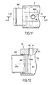
- the exchanger 1 comprises a calender 2 of axis longitudinal 3, and a tubular bundle housed in the cavity defined in the shell; the shell has a plurality of flat outer faces 4 to 13 (see FIG. 3) elongate and parallel to the axis 3; on the face 10 open two channels 14 and 15 of connecting the cavity defined by the shell to a fluid such as oil to cool.
- the calender is obtained by extrusion of aluminum; the resulting profile is quenched and cut into sections such as that illustrated in FIGS. 2 and 3; each end longitudinal axis is machined to obtain a chamfer 16, 17 facilitating the introduction of the tubular bundle equipped with two annular sealing seals (pins 19, 20 in FIG. 8) in the cavity 18 defined by the shell without damaging the seals.
- the walls 10 to 12 delimit a longitudinal rib 23 parallel to the axis 3, in which are drilled the channels 14, 15 of axes 21 and 22 radial.
- each duct 14, 15 comprises a portion external threaded end 24 extending from the face 10 to allow the screwing of a fitting not shown; the internal part of the conduit through which it leads to the cylindrical inner face 25 of the cavity 18, has a diameter 26 less than diameter 27 of the orifice through which the conduit opens on the face 10; this results from the presence of an annular collar 28 formed in the wall 23 during the drilling of conduits 14, 15 by a profiled drill for this purpose; the flange 28 has a thickness 29 sufficiently weak (for example of the order of 1 to 2 millimeters) to be able to be deformed by the action of a tool pressed on the inner face 30 inclined, according to the arrow Figure 4; this allows to pass at least part of this collar of the initial configuration - reference 28 figure 4 - where the flange is flush with face 25, at the final configuration - marked 28a figure 4 - where the deformed flange protrudes relative to the face 25, a value 32, for example close to one or two millimeters
- This mode of deformation of the collar requires the use of a material having sufficient elongation at break, for producing the calender; at this effect, the use of extruded and tempered aluminum is more favorable than of cast aluminum and / or injected.
- the hollow section (or tubular bar) used to form the shell can be obtained by plastic extrusion, or by hot-spinning or cold-drawing of a metal, in particular an aluminum alloy, copper or steel.
- the beam 34 comprises a plurality of tubes 35 parallel to its longitudinal axis 33, a plurality of baffles 36, 37 planes perpendicular to the axis 33, and two end pieces 38.
- the contour of the baffles 36, 37 is largely circular (in diameter adapted to that of the cavity 18) and partly rectilinear 36a, 37a, so that the baffles have a truncated disc shape; the baffles 36 having their edge rectilinear 36a in the lower part are arranged, along the axis 33, alternately with the baffles 37 having their straight edge 37a at the top, so that these baffles delimit with the grille a labyrinth forcing the second fluid following a winding path 39 figure 5.
- Each piece 38 has a first portion 380 in the form of a thick disc in which holes are drilled receiving the ends 350 of the tubes 35; this part, which extends transversely to the axis 33, form the tube plate cleanly called.
- the first part 380 is extended at the periphery of its internal face 3800 by a second portion 381 of the piece 38, which is shaped like a short stretch of thin tube of axis 33; at one end of this section, a notch 3810 is formed in the tubular wall of the section, which extends in a circular pattern whose diameter 40 is adapted to the dimensions (in particular to the diameter) of the projection 28a ( Figure 4) formed on the inner face of the calender.
- the first part 380 of the piece 38 is further extended on the periphery of its outer face 3801 by a third part 382 of the part 38 which is roughly in the form of a section of tubular shaft 33 and whose outer face has a groove ring 41 provided for receiving one of the seals (19, 20 FIG. calender, and an annular rib 42 protruding from the portion 3820 central of that Part 382; the latter can thus, as illustrated in FIG. 7, receive one end of a connecting tube 43 force-fitted around the rib 42 and the cylindrical portion 3820 against which the tube 43 can be held tight by a strapping collar not shown.
- each of the notches provided in the end pieces is arranged respectively opposite the inlet and outlet ports 14, 15 and receives a portion of the annular projections extending these openings, so that the beam is immobilized in the calender.
- the tubular portion 381 of axis 33 extending the tubular plate 380 of the bundle comprises a tongue-shaped portion 3811 which has been deformed after positioning the beam in the shell, so that it extends inside the orifice 14 of fluid passage, bearing against the wall delimiting this orifice; the tongue 3811 prevents a sliding of the beam in the calender, according to their common axis 3, 33 in the direction marked by the arrow 100; in further equipping the second tubular plate (not shown) of the same exchanger of such a tongue, it is also forbidden such a sliding in the opposite direction, as well as a rotation of the beam.
- a tubular sleeve 99 extends to the inside of the conduit 14 of fluid passage pierced in the rib 23 of the shell, along the axis 21 of the conduit 14, on the walls of which leads this sleeve rests.
- the sleeve 99 protrudes from the inner face of the calender; from this done, it is engaged in a notch 3810 identical or similar to that described above, so that it limits the sliding of the beam in the calender; by equipping in addition a second duct (as marked 15) by a second sleeve protruding inside the grille, the sliding and rotation of the beam in the grille.
Landscapes
- Engineering & Computer Science (AREA)
- Physics & Mathematics (AREA)
- Thermal Sciences (AREA)
- Mechanical Engineering (AREA)
- General Engineering & Computer Science (AREA)
- Heat-Exchange Devices With Radiators And Conduit Assemblies (AREA)
Applications Claiming Priority (2)
| Application Number | Priority Date | Filing Date | Title |
|---|---|---|---|
| FR0207708A FR2841331B1 (fr) | 2002-06-21 | 2002-06-21 | Echangeurs multitubulaires et procede de fabrication de ces echangeurs |
| FR0207708 | 2002-06-21 |
Publications (2)
| Publication Number | Publication Date |
|---|---|
| EP1376039A1 true EP1376039A1 (de) | 2004-01-02 |
| EP1376039B1 EP1376039B1 (de) | 2008-11-12 |
Family
ID=29717077
Family Applications (1)
| Application Number | Title | Priority Date | Filing Date |
|---|---|---|---|
| EP03358008A Expired - Lifetime EP1376039B1 (de) | 2002-06-21 | 2003-06-18 | Multiröhren- Wärmetauscher und dessen Herstellung |
Country Status (5)
| Country | Link |
|---|---|
| US (1) | US6840306B2 (de) |
| EP (1) | EP1376039B1 (de) |
| AT (1) | ATE414252T1 (de) |
| DE (1) | DE60324631D1 (de) |
| FR (1) | FR2841331B1 (de) |
Cited By (1)
| Publication number | Priority date | Publication date | Assignee | Title |
|---|---|---|---|---|
| WO2010044723A3 (en) * | 2008-10-15 | 2010-09-10 | Alfa Laval Corporate Ab | A plate heat exchanger |
Families Citing this family (10)
| Publication number | Priority date | Publication date | Assignee | Title |
|---|---|---|---|---|
| US7243711B2 (en) * | 2004-03-30 | 2007-07-17 | Caterpillar Inc. | Efficient heat exchanger and engine using same |
| FR2871559B1 (fr) * | 2004-06-14 | 2006-09-22 | Georges Favier | Coeur de pompe a chaleur compact de type eau/eau |
| US8794299B2 (en) * | 2007-02-27 | 2014-08-05 | Modine Manufacturing Company | 2-Pass heat exchanger including thermal expansion joints |
| DE102008011557B4 (de) * | 2007-12-12 | 2010-02-25 | GEA MASCHINENKüHLTECHNIK GMBH | Abgasrückkühler für eine Verbrennungskraftmaschine |
| US8517086B2 (en) * | 2008-02-29 | 2013-08-27 | Caterpillar Inc. | Composite heat exchanger end structure |
| US20110083619A1 (en) * | 2009-10-08 | 2011-04-14 | Master Bashir I | Dual enhanced tube for vapor generator |
| KR102001250B1 (ko) * | 2013-07-12 | 2019-07-19 | 한국전력공사 | 다중 통로 교류 열교환기 |
| EA029786B1 (ru) * | 2016-08-05 | 2018-05-31 | Общество с ограниченной ответственностью Урало-Сибирская Компания "НЕКСАН" | Кожухотрубный конденсатор |
| EP3564613A1 (de) * | 2018-05-03 | 2019-11-06 | Mann+Hummel GmbH | Wärmetauscher, luftansaugsystem mit einem wärmetauscher und verfahren zur montage eines wärmetauschers |
| JP7042383B1 (ja) * | 2021-10-29 | 2022-03-25 | 岩井機械工業株式会社 | 多管式熱交換器及び熱交換システム |
Citations (7)
| Publication number | Priority date | Publication date | Assignee | Title |
|---|---|---|---|---|
| US1994779A (en) * | 1932-04-16 | 1935-03-19 | Andale Co | Heat exchange apparatus |
| GB734008A (en) * | 1952-02-05 | 1955-07-20 | Bristol Aeroplane Co Ltd | Improvements in or relating to heat exchangers |
| US3363680A (en) * | 1966-07-21 | 1968-01-16 | Du Pont | Plastic tube heat exchanger with novel header construction |
| JPS60169094A (ja) * | 1984-02-10 | 1985-09-02 | Hitachi Ltd | 熱交換器 |
| DE3610314A1 (de) * | 1986-03-26 | 1987-10-01 | Vni I Pk I Atomnogo Energet Ma | Schlangenrohrwaermeuebertrager |
| DE4344257A1 (de) * | 1992-12-23 | 1994-06-30 | Framatome Sa | Wärmetauscher mit Haltevorrichtung |
| EP1146310A1 (de) * | 2000-04-11 | 2001-10-17 | Mota | Verbesserung von Rohrbündelwärmetauschern und Verfahren zu deren Herstellung |
Family Cites Families (10)
| Publication number | Priority date | Publication date | Assignee | Title |
|---|---|---|---|---|
| FR623803A (fr) | 1925-11-02 | 1927-07-01 | Perfectionnements aux dispositifs échangeurs de chaleur à faisceaux tubulaires | |
| US1955006A (en) * | 1932-12-02 | 1934-04-17 | Standard Oil Dev Co | Lubricated baffle for heat exchangers |
| US2956704A (en) * | 1957-05-15 | 1960-10-18 | Griscom Russell Co | Removable tube sheet construction for heat exchangers |
| US3079992A (en) * | 1961-02-06 | 1963-03-05 | Baldwin Lima Hamilton Corp | Heat exchanger closure construction |
| US3223154A (en) * | 1962-01-25 | 1965-12-14 | Young Radiator Co | Shell-and-tube heat-exchanger |
| US3915337A (en) * | 1972-12-05 | 1975-10-28 | Foster Wheeler Energy Corp | Pressure vessel with shear stud closure assembly and method of assembling same |
| US3863713A (en) * | 1973-08-27 | 1975-02-04 | Stewart Warner Corp | Heat exchanger |
| US3948315A (en) * | 1974-08-13 | 1976-04-06 | Brown Fintube Company | Closure for heat exchanger |
| US4421160A (en) * | 1980-10-16 | 1983-12-20 | Chicago Bridge & Iron Company | Shell and tube heat exchanger with removable tubes and tube sheets |
| US4589478A (en) * | 1985-08-19 | 1986-05-20 | United Aircraft Products, Inc. | Pressure protected tubular heat exchanger |
-
2002
- 2002-06-21 FR FR0207708A patent/FR2841331B1/fr not_active Expired - Lifetime
-
2003
- 2003-02-11 US US10/361,644 patent/US6840306B2/en not_active Expired - Lifetime
- 2003-06-18 DE DE60324631T patent/DE60324631D1/de not_active Expired - Lifetime
- 2003-06-18 EP EP03358008A patent/EP1376039B1/de not_active Expired - Lifetime
- 2003-06-18 AT AT03358008T patent/ATE414252T1/de not_active IP Right Cessation
Patent Citations (7)
| Publication number | Priority date | Publication date | Assignee | Title |
|---|---|---|---|---|
| US1994779A (en) * | 1932-04-16 | 1935-03-19 | Andale Co | Heat exchange apparatus |
| GB734008A (en) * | 1952-02-05 | 1955-07-20 | Bristol Aeroplane Co Ltd | Improvements in or relating to heat exchangers |
| US3363680A (en) * | 1966-07-21 | 1968-01-16 | Du Pont | Plastic tube heat exchanger with novel header construction |
| JPS60169094A (ja) * | 1984-02-10 | 1985-09-02 | Hitachi Ltd | 熱交換器 |
| DE3610314A1 (de) * | 1986-03-26 | 1987-10-01 | Vni I Pk I Atomnogo Energet Ma | Schlangenrohrwaermeuebertrager |
| DE4344257A1 (de) * | 1992-12-23 | 1994-06-30 | Framatome Sa | Wärmetauscher mit Haltevorrichtung |
| EP1146310A1 (de) * | 2000-04-11 | 2001-10-17 | Mota | Verbesserung von Rohrbündelwärmetauschern und Verfahren zu deren Herstellung |
Non-Patent Citations (1)
| Title |
|---|
| PATENT ABSTRACTS OF JAPAN vol. 010, no. 006 (M - 445) 11 January 1986 (1986-01-11) * |
Cited By (1)
| Publication number | Priority date | Publication date | Assignee | Title |
|---|---|---|---|---|
| WO2010044723A3 (en) * | 2008-10-15 | 2010-09-10 | Alfa Laval Corporate Ab | A plate heat exchanger |
Also Published As
| Publication number | Publication date |
|---|---|
| DE60324631D1 (de) | 2008-12-24 |
| EP1376039B1 (de) | 2008-11-12 |
| FR2841331B1 (fr) | 2005-02-25 |
| US6840306B2 (en) | 2005-01-11 |
| ATE414252T1 (de) | 2008-11-15 |
| US20030234099A1 (en) | 2003-12-25 |
| FR2841331A1 (fr) | 2003-12-26 |
Similar Documents
| Publication | Publication Date | Title |
|---|---|---|
| EP1376039B1 (de) | Multiröhren- Wärmetauscher und dessen Herstellung | |
| FR2623606A1 (fr) | Echangeur de chaleur comportant des chicanes presentant des joints d'etancheites | |
| EP2514980B1 (de) | Einsatz für thermoplastische Halterung, und Zusammenbauverfahren des Einsatzes mit der Halterung | |
| EP2714303A1 (de) | Verfahren zur herstellung eines metallschaums mit kanälen und resultierender metallschaum | |
| WO2008025617A1 (fr) | Boitier de distribution d'un fluide caloporteur pour un echangeur de chaleur et echangeur de chaleur comportant un tel boitier | |
| FR2967250A1 (fr) | Echangeur de chaleur avec dispositif de raccordement | |
| FR2665384A1 (fr) | Procede de realisation d'une piece moulee en al ou ses alliages munie de canaux integres. | |
| EP1146310B1 (de) | Verbesserung von Rohrbündelwärmetauschern und Verfahren zu deren Herstellung | |
| FR3075346A1 (fr) | Boite collectrice d'un echangeur thermique munie d'un organe de maintien et/ou de positionnement angulaire d'un dispositif de distribution d'un fluide refrigerant | |
| EP1533558B1 (de) | Koaxiale Rohrverbindung | |
| EP2946136B1 (de) | Schnelllverbindervorrichtung | |
| EP1500445A2 (de) | Grosse Metallform | |
| CA2987540A1 (fr) | Profile creux tel qu'un tube realise en materiaux composite thermodurcissable et son procede | |
| FR2494418A1 (fr) | Echangeur de chaleur pour fluides divers, liquides ou gazeux comportant des demi-lames assemblees delimitant un faisceau tubulaire | |
| FR2905452A1 (fr) | Boitier de distribution d'un fluide pour echangeur de chaleur et echangeur de chaleur comportant un tel boitier. | |
| EP2893278B1 (de) | Austauschelement für einen wärmetauscher, wärmetauscher mit einem solchen austauschelement und verfahren zur herstellung eines solchen austauschelements | |
| EP0792706A1 (de) | Gusswalz zum Strangguss von Metall, zwischen oder auf den Giesswalzen | |
| WO2021018759A1 (fr) | Élément mâle de raccord fluidique, raccord fluidique comprenant un tel élément mâle et procédé d'assemblage d'un tel élément mâle | |
| FR2812682A1 (fr) | Soupape de construction legere en plusieurs parties pour moteurs a combustion interne | |
| WO2010149876A2 (fr) | Amélioration aux vannes à corps à double paroi | |
| FR3045773A1 (fr) | Conduit principal d'un circuit de circulation d'un fluide comprenant un element de prelevement du fluide | |
| EP3017164B1 (de) | Mithilfe von formen mit inneren aussparungen hergestelltes metallteil, verfahren zur herstellung davon und verbrennungsmotor mit solch einem teil | |
| FR2866419A1 (fr) | Boite collectrice munie d'une tubulure de raccordement pour un echangeur de chaleur brase. | |
| FR3121059A1 (fr) | Procédé de fabrication d’un échangeur de chaleur et échangeur de chaleur obtenu par un tel procédé | |
| EP1503112B1 (de) | Adapterring zwischen Motor und Getriebe eines Kraftfahrzeuzes |
Legal Events
| Date | Code | Title | Description |
|---|---|---|---|
| PUAI | Public reference made under article 153(3) epc to a published international application that has entered the european phase |
Free format text: ORIGINAL CODE: 0009012 |
|
| AK | Designated contracting states |
Kind code of ref document: A1 Designated state(s): AT BE BG CH CY CZ DE DK EE ES FI FR GB GR HU IE IT LI LU MC NL PT RO SE SI SK TR |
|
| AX | Request for extension of the european patent |
Extension state: AL LT LV MK |
|
| 17P | Request for examination filed |
Effective date: 20040512 |
|
| AKX | Designation fees paid |
Designated state(s): AT BE BG CH CY CZ DE DK EE ES FI FR GB GR HU IE IT LI LU MC NL PT RO SE SI SK TR |
|
| 17Q | First examination report despatched |
Effective date: 20060420 |
|
| GRAP | Despatch of communication of intention to grant a patent |
Free format text: ORIGINAL CODE: EPIDOSNIGR1 |
|
| GRAS | Grant fee paid |
Free format text: ORIGINAL CODE: EPIDOSNIGR3 |
|
| GRAA | (expected) grant |
Free format text: ORIGINAL CODE: 0009210 |
|
| AK | Designated contracting states |
Kind code of ref document: B1 Designated state(s): AT BE BG CH CY CZ DE DK EE ES FI FR GB GR HU IE IT LI LU MC NL PT RO SE SI SK TR |
|
| REG | Reference to a national code |
Ref country code: GB Ref legal event code: FG4D Free format text: NOT ENGLISH |
|
| REG | Reference to a national code |
Ref country code: CH Ref legal event code: EP |
|
| REG | Reference to a national code |
Ref country code: IE Ref legal event code: FG4D Free format text: LANGUAGE OF EP DOCUMENT: FRENCH |
|
| REF | Corresponds to: |
Ref document number: 60324631 Country of ref document: DE Date of ref document: 20081224 Kind code of ref document: P |
|
| REG | Reference to a national code |
Ref country code: SE Ref legal event code: TRGR |
|
| PG25 | Lapsed in a contracting state [announced via postgrant information from national office to epo] |
Ref country code: AT Free format text: LAPSE BECAUSE OF FAILURE TO SUBMIT A TRANSLATION OF THE DESCRIPTION OR TO PAY THE FEE WITHIN THE PRESCRIBED TIME-LIMIT Effective date: 20081112 Ref country code: ES Free format text: LAPSE BECAUSE OF FAILURE TO SUBMIT A TRANSLATION OF THE DESCRIPTION OR TO PAY THE FEE WITHIN THE PRESCRIBED TIME-LIMIT Effective date: 20090223 |
|
| NLV1 | Nl: lapsed or annulled due to failure to fulfill the requirements of art. 29p and 29m of the patents act | ||
| PG25 | Lapsed in a contracting state [announced via postgrant information from national office to epo] |
Ref country code: SI Free format text: LAPSE BECAUSE OF FAILURE TO SUBMIT A TRANSLATION OF THE DESCRIPTION OR TO PAY THE FEE WITHIN THE PRESCRIBED TIME-LIMIT Effective date: 20081112 Ref country code: FI Free format text: LAPSE BECAUSE OF FAILURE TO SUBMIT A TRANSLATION OF THE DESCRIPTION OR TO PAY THE FEE WITHIN THE PRESCRIBED TIME-LIMIT Effective date: 20081112 Ref country code: NL Free format text: LAPSE BECAUSE OF FAILURE TO SUBMIT A TRANSLATION OF THE DESCRIPTION OR TO PAY THE FEE WITHIN THE PRESCRIBED TIME-LIMIT Effective date: 20081112 |
|
| REG | Reference to a national code |
Ref country code: IE Ref legal event code: FD4D |
|
| PG25 | Lapsed in a contracting state [announced via postgrant information from national office to epo] |
Ref country code: IE Free format text: LAPSE BECAUSE OF FAILURE TO SUBMIT A TRANSLATION OF THE DESCRIPTION OR TO PAY THE FEE WITHIN THE PRESCRIBED TIME-LIMIT Effective date: 20081112 Ref country code: BG Free format text: LAPSE BECAUSE OF FAILURE TO SUBMIT A TRANSLATION OF THE DESCRIPTION OR TO PAY THE FEE WITHIN THE PRESCRIBED TIME-LIMIT Effective date: 20090212 Ref country code: RO Free format text: LAPSE BECAUSE OF FAILURE TO SUBMIT A TRANSLATION OF THE DESCRIPTION OR TO PAY THE FEE WITHIN THE PRESCRIBED TIME-LIMIT Effective date: 20081112 Ref country code: EE Free format text: LAPSE BECAUSE OF FAILURE TO SUBMIT A TRANSLATION OF THE DESCRIPTION OR TO PAY THE FEE WITHIN THE PRESCRIBED TIME-LIMIT Effective date: 20081112 Ref country code: DK Free format text: LAPSE BECAUSE OF FAILURE TO SUBMIT A TRANSLATION OF THE DESCRIPTION OR TO PAY THE FEE WITHIN THE PRESCRIBED TIME-LIMIT Effective date: 20081112 |
|
| PG25 | Lapsed in a contracting state [announced via postgrant information from national office to epo] |
Ref country code: PT Free format text: LAPSE BECAUSE OF FAILURE TO SUBMIT A TRANSLATION OF THE DESCRIPTION OR TO PAY THE FEE WITHIN THE PRESCRIBED TIME-LIMIT Effective date: 20090413 Ref country code: CZ Free format text: LAPSE BECAUSE OF FAILURE TO SUBMIT A TRANSLATION OF THE DESCRIPTION OR TO PAY THE FEE WITHIN THE PRESCRIBED TIME-LIMIT Effective date: 20081112 |
|
| PLBE | No opposition filed within time limit |
Free format text: ORIGINAL CODE: 0009261 |
|
| STAA | Information on the status of an ep patent application or granted ep patent |
Free format text: STATUS: NO OPPOSITION FILED WITHIN TIME LIMIT |
|
| PG25 | Lapsed in a contracting state [announced via postgrant information from national office to epo] |
Ref country code: SK Free format text: LAPSE BECAUSE OF FAILURE TO SUBMIT A TRANSLATION OF THE DESCRIPTION OR TO PAY THE FEE WITHIN THE PRESCRIBED TIME-LIMIT Effective date: 20081112 |
|
| 26N | No opposition filed |
Effective date: 20090813 |
|
| BERE | Be: lapsed |
Owner name: MOTA Effective date: 20090630 |
|
| PG25 | Lapsed in a contracting state [announced via postgrant information from national office to epo] |
Ref country code: MC Free format text: LAPSE BECAUSE OF NON-PAYMENT OF DUE FEES Effective date: 20090630 |
|
| REG | Reference to a national code |
Ref country code: CH Ref legal event code: PL |
|
| PG25 | Lapsed in a contracting state [announced via postgrant information from national office to epo] |
Ref country code: CH Free format text: LAPSE BECAUSE OF NON-PAYMENT OF DUE FEES Effective date: 20090630 Ref country code: LI Free format text: LAPSE BECAUSE OF NON-PAYMENT OF DUE FEES Effective date: 20090630 |
|
| PG25 | Lapsed in a contracting state [announced via postgrant information from national office to epo] |
Ref country code: BE Free format text: LAPSE BECAUSE OF NON-PAYMENT OF DUE FEES Effective date: 20090630 |
|
| PG25 | Lapsed in a contracting state [announced via postgrant information from national office to epo] |
Ref country code: GR Free format text: LAPSE BECAUSE OF FAILURE TO SUBMIT A TRANSLATION OF THE DESCRIPTION OR TO PAY THE FEE WITHIN THE PRESCRIBED TIME-LIMIT Effective date: 20090213 |
|
| PG25 | Lapsed in a contracting state [announced via postgrant information from national office to epo] |
Ref country code: LU Free format text: LAPSE BECAUSE OF NON-PAYMENT OF DUE FEES Effective date: 20090618 |
|
| PG25 | Lapsed in a contracting state [announced via postgrant information from national office to epo] |
Ref country code: HU Free format text: LAPSE BECAUSE OF FAILURE TO SUBMIT A TRANSLATION OF THE DESCRIPTION OR TO PAY THE FEE WITHIN THE PRESCRIBED TIME-LIMIT Effective date: 20090513 |
|
| PG25 | Lapsed in a contracting state [announced via postgrant information from national office to epo] |
Ref country code: TR Free format text: LAPSE BECAUSE OF FAILURE TO SUBMIT A TRANSLATION OF THE DESCRIPTION OR TO PAY THE FEE WITHIN THE PRESCRIBED TIME-LIMIT Effective date: 20081112 |
|
| PG25 | Lapsed in a contracting state [announced via postgrant information from national office to epo] |
Ref country code: CY Free format text: LAPSE BECAUSE OF FAILURE TO SUBMIT A TRANSLATION OF THE DESCRIPTION OR TO PAY THE FEE WITHIN THE PRESCRIBED TIME-LIMIT Effective date: 20081112 |
|
| REG | Reference to a national code |
Ref country code: FR Ref legal event code: PLFP Year of fee payment: 14 |
|
| REG | Reference to a national code |
Ref country code: FR Ref legal event code: PLFP Year of fee payment: 15 |
|
| REG | Reference to a national code |
Ref country code: FR Ref legal event code: PLFP Year of fee payment: 16 |
|
| PGFP | Annual fee paid to national office [announced via postgrant information from national office to epo] |
Ref country code: FR Payment date: 20220323 Year of fee payment: 20 |
|
| PGFP | Annual fee paid to national office [announced via postgrant information from national office to epo] |
Ref country code: SE Payment date: 20220623 Year of fee payment: 20 Ref country code: IT Payment date: 20220608 Year of fee payment: 20 Ref country code: GB Payment date: 20220616 Year of fee payment: 20 Ref country code: DE Payment date: 20220607 Year of fee payment: 20 |
|
| REG | Reference to a national code |
Ref country code: DE Ref legal event code: R082 Ref document number: 60324631 Country of ref document: DE Representative=s name: CBDL PATENTANWAELTE GBR, DE |
|
| REG | Reference to a national code |
Ref country code: DE Ref legal event code: R071 Ref document number: 60324631 Country of ref document: DE |
|
| REG | Reference to a national code |
Ref country code: GB Ref legal event code: PE20 Expiry date: 20230617 |
|
| REG | Reference to a national code |
Ref country code: SE Ref legal event code: EUG |
|
| PG25 | Lapsed in a contracting state [announced via postgrant information from national office to epo] |
Ref country code: GB Free format text: LAPSE BECAUSE OF EXPIRATION OF PROTECTION Effective date: 20230617 |