EP1376000B1 - Trennschieber - Google Patents
Trennschieber Download PDFInfo
- Publication number
- EP1376000B1 EP1376000B1 EP03013507A EP03013507A EP1376000B1 EP 1376000 B1 EP1376000 B1 EP 1376000B1 EP 03013507 A EP03013507 A EP 03013507A EP 03013507 A EP03013507 A EP 03013507A EP 1376000 B1 EP1376000 B1 EP 1376000B1
- Authority
- EP
- European Patent Office
- Prior art keywords
- slider
- passage
- hard
- shiftable
- housing
- Prior art date
- Legal status (The legal status is an assumption and is not a legal conclusion. Google has not performed a legal analysis and makes no representation as to the accuracy of the status listed.)
- Expired - Lifetime
Links
- 238000007789 sealing Methods 0.000 claims abstract description 38
- 239000000463 material Substances 0.000 claims abstract description 28
- 239000012530 fluid Substances 0.000 claims description 11
- 230000003746 surface roughness Effects 0.000 claims description 3
- 230000000694 effects Effects 0.000 description 5
- 239000007788 liquid Substances 0.000 description 5
- 239000007789 gas Substances 0.000 description 4
- 239000000919 ceramic Substances 0.000 description 3
- 239000007787 solid Substances 0.000 description 3
- OKTJSMMVPCPJKN-UHFFFAOYSA-N Carbon Chemical compound [C] OKTJSMMVPCPJKN-UHFFFAOYSA-N 0.000 description 2
- VYPSYNLAJGMNEJ-UHFFFAOYSA-N Silicium dioxide Chemical compound O=[Si]=O VYPSYNLAJGMNEJ-UHFFFAOYSA-N 0.000 description 2
- 229910002804 graphite Inorganic materials 0.000 description 2
- 239000010439 graphite Substances 0.000 description 2
- 238000000926 separation method Methods 0.000 description 2
- 239000000126 substance Substances 0.000 description 2
- 238000005299 abrasion Methods 0.000 description 1
- 239000003082 abrasive agent Substances 0.000 description 1
- 239000002253 acid Substances 0.000 description 1
- 210000001124 body fluid Anatomy 0.000 description 1
- 239000010839 body fluid Substances 0.000 description 1
- 229910010293 ceramic material Inorganic materials 0.000 description 1
- 239000003610 charcoal Substances 0.000 description 1
- 229940090961 chromium dioxide Drugs 0.000 description 1
- IAQWMWUKBQPOIY-UHFFFAOYSA-N chromium(4+);oxygen(2-) Chemical compound [O-2].[O-2].[Cr+4] IAQWMWUKBQPOIY-UHFFFAOYSA-N 0.000 description 1
- AYTAKQFHWFYBMA-UHFFFAOYSA-N chromium(IV) oxide Inorganic materials O=[Cr]=O AYTAKQFHWFYBMA-UHFFFAOYSA-N 0.000 description 1
- 238000000576 coating method Methods 0.000 description 1
- 238000006073 displacement reaction Methods 0.000 description 1
- 210000004907 gland Anatomy 0.000 description 1
- 239000008187 granular material Substances 0.000 description 1
- 238000002955 isolation Methods 0.000 description 1
- 238000003754 machining Methods 0.000 description 1
- 229910052751 metal Inorganic materials 0.000 description 1
- 239000002184 metal Substances 0.000 description 1
- 239000004810 polytetrafluoroethylene Substances 0.000 description 1
- 229920001343 polytetrafluoroethylene Polymers 0.000 description 1
- 230000005855 radiation Effects 0.000 description 1
- HBMJWWWQQXIZIP-UHFFFAOYSA-N silicon carbide Chemical compound [Si+]#[C-] HBMJWWWQQXIZIP-UHFFFAOYSA-N 0.000 description 1
- 229910010271 silicon carbide Inorganic materials 0.000 description 1
- 235000012239 silicon dioxide Nutrition 0.000 description 1
- 239000000377 silicon dioxide Substances 0.000 description 1
- UONOETXJSWQNOL-UHFFFAOYSA-N tungsten carbide Chemical compound [W+]#[C-] UONOETXJSWQNOL-UHFFFAOYSA-N 0.000 description 1
- 239000002351 wastewater Substances 0.000 description 1
Images

Classifications
-
- F—MECHANICAL ENGINEERING; LIGHTING; HEATING; WEAPONS; BLASTING
- F16—ENGINEERING ELEMENTS AND UNITS; GENERAL MEASURES FOR PRODUCING AND MAINTAINING EFFECTIVE FUNCTIONING OF MACHINES OR INSTALLATIONS; THERMAL INSULATION IN GENERAL
- F16K—VALVES; TAPS; COCKS; ACTUATING-FLOATS; DEVICES FOR VENTING OR AERATING
- F16K3/00—Gate valves or sliding valves, i.e. cut-off apparatus with closing members having a sliding movement along the seat for opening and closing
- F16K3/02—Gate valves or sliding valves, i.e. cut-off apparatus with closing members having a sliding movement along the seat for opening and closing with flat sealing faces; Packings therefor
- F16K3/0263—Gate valves or sliding valves, i.e. cut-off apparatus with closing members having a sliding movement along the seat for opening and closing with flat sealing faces; Packings therefor using particular material or covering means
Definitions
- the invention relates to a gate valve for shutting off pipelines, comprising a gate housing containing a passage and a slide movable therein.
- Shutters are used to shut off pipes that carry fluids.
- the fluids may be gases, liquids, solids, and more particularly multi-phase systems in which, for example, solids are transported together with a gaseous or liquid carrier medium. All of these materials have a broad spectrum. So solids can be moved in the form of granular and abrasive material to logs or stones through the pipeline.
- the liquids and gases may be aggressive substances, such as acid or any type of wastewater.
- the sizes of dividers can vary within a wide range. A characteristic measure is the diameter of the passage or adjacent tubes. Frequently, this diameter is on the order of 40 cm.
- the slider In the slider housing of a separating slide, the slider is linearly movable within a guide track to be brought from the opening position to the closing position. This adjustment is usually pneumatic or hydraulic or motorized. In each of these two positions, the slide must be sealed with respect to the passage to prevent the medium from escaping uncontrollably on the slide.
- annular soft seals are used for the sealing of the slide. These are made of graphite, PTFE, filled with graphite (Manoy), or from electric charcoal. Such seals are quickly destroyed in the case of difficult media, by mechanical action, such as abrasion or by chemical or thermal effects. Although the seals are spaced a certain distance from the periphery of the passage, they are reached by the medium.
- sealing separation slides which have in the valve body fluid cylinder, which are contained in annular sealing body.
- Each sealing body is provided on the surface facing the slider with a soft seal with which it presses against the slide. This is intended to compensate for any wear of the soft seals, and it is ensured that the annular piston are always pressed with the required contact force against the slide.
- a separating slide, from which the preamble of claim 1 proceeds, is described in DE 35 45 266 A1.
- the slide plate and the sealing body are formed as one-piece sintered ceramic compacts having a roughness of less than 0.4 microns.
- Such one-piece sintered ceramic compacts must be manufactured with high accuracy because they are rigid and do not allow deformations.
- the slide plate In order to obtain the required strength, the slide plate must have a relatively large thickness. As a result, in turn, the dimensions of the entire separator slide structure are increased and the weight is increased.
- the invention has for its object to provide a separator, which does not nachläset without significant wear even in difficult fluids in its tightness. In other words, the life of the seal should be extended.
- annular sealing body represent pistons, which are acted upon either with a gas (compressed air) or with a liquid.
- a gas compressed air
- a liquid In the case of a fluid supply is due to the incompressibility of the liquid to provide a gas pressure accumulator to achieve the required compliance of the pressing force.
- the hard material layer preferably consists of a carbide or oxide in ceramic or metallic bond.
- Such hard coatings are known and therefore need not be explained in detail here.
- silicon carbide or silicon dioxide is suitable.
- the surface roughness of the hard material layers is preferably less than 2 ⁇ m and in particular less than 0.4 ⁇ m.
- the low surface roughness is achieved after the application of the hard material layer by superfinishing, in particular by honing or by lapping, in which a pair of fine finishing takes place, in which the surfaces to be machined are mutually rubbed against each other, so that an exact full-surface mutual adjustment takes place, however just match these two individual surfaces with the required sealing effect.
- the contact surface of the slider in the direction of movement of the slider has a width which is smaller than that of the sealing body, wherein the remaining area of the slider facing surface is arranged back.
- the illustrated isolating slide has a housing 10, which consists of two housing halves 10a, 10b, which are set axially against each other and screwed together.
- the housing halves have mutually aligned bores which form a passage 11.
- a flange 12 for flanging a pipe.
- an elongated cavity is formed, in which a plate-shaped slide 13, which has an opening 14 of about the same size as the passage 11, is displaceable transversely to the axial direction of the housing.
- the housing 10 has the plane of the slider 13 has two opposite sides projecting receiving spaces 15,16, one of which can receive one half of the slider 13, while the other half is in the housing 10.
- a pneumatic cylinder 18 is mounted on rods 17, which includes a piston 19.
- the pneumatic cylinder is controlled by a valve 20 which is connected to a compressed air source (not shown).
- a piston rod 21 is connected, which projects into the end of the receiving space 16 and is connected at its other end to the slider 13.
- the passage of the piston rod 21 through the end wall 22 of the receiving space 16 is sealed with a gland seal 23.
- the receiving spaces have 15,16 shielding walls 24 to keep heat radiation from the walls of the isolation slide.
- the slide 13 is shown in its shut-off position, in which the opening 14 is located in the receiving space 15, while the housing 10 includes the closed plate portion of the slider 13, which blocks the passage 11.
- the piston rod 21 is moved out of the pneumatic cylinder 18. If the slide 13 is to be brought into the open position, the piston 19 is moved back in the cylinder 18, so that the opening 14 of the slide 13 adjusts itself coaxially to the passage 11.
- each housing half has an annular fluid cylinder 27 (FIG. 3), which is incorporated as an axial groove in the housing half.
- Each fluid cylinder 27 includes an annular rigid sealing body 28 which forms an annular piston.
- the annular piston 28 surrounds the passage 11 on each side of the slider 13.
- Each sealing body 28 includes on its inside two sealing rings 29 and on its outside also two sealing rings 30 for sealing against the pneumatic annular fluid cylinder 27.
- In each fluid cylinder 27 leads at the outer end 31 a pressure line 32 and 33 into it, in order to drive the sealing body 28 in the direction of the slider 13.
- Each sealing body 28 has a contact surface 34 on the side facing the slider 13. This is narrower than the width of the sealing body, and it goes over a sloping shoulder 35 in a past range 36 over.
- the annular disk-shaped contact surface 34 is located on the sealing body 28 at that end which is adjacent to the passage 11, while the portion 36 is removed from the passage.
- the contact surface 34 is coated with a hard material layer 37, which also extends over part of the oblique shoulder 35.
- the slider 13 is also provided on both sides with two layers of hard material 38,39 ( Figure 5). These hard material layers 38, 39 are annular disks. The one hard material layer 38 is disposed around the opening 14 of the slider 13, and the other hard material layer 39 is disposed around the closing surface of the slider, which is located in the passage 11 of the housing when the slider is in the closed position as shown in FIGS Figures 1 and 2 is shown.
- the hard material layers 37, 38, 39 are preferably made of ceramic material, such as chromium dioxide, or of hard metal, such as tungsten carbide. Following their application, they are treated by microfinishing, first by grinding and then by honing or lapping. The roughness is at most Ra 4, which corresponds to 4 ⁇ m . In particular, it is in the range of Ra 0.4, ie 0.4 ⁇ m and below.
- the width of the contact surface 34 is less than 10 mm and in particular about 5 mm. It should not be larger than required for the sealing effect.
- the finest machining of the surfaces of the hard material layers is done by pairwise lapping, wherein two hard material layers are stacked and rubbed against each other. These two hard material layers are those of the slider 13 and the associated sealing body. Those layers of hard material which are later to be sealing against one another are processed by mutual rubbing so that the hard material layers fit together in pairs.
- the pressurization of the sealing body 28 takes place from the cylinder 18.
- a line 40 leads to the rear end of the cylinder 18. This line serves to generate in the cylinder 18 a force acting on the piston 19 force, which drives the slider 13 in the closed position.
- the line 40 is connected via further lines 41,42,43 with a manifold 44 to which the lines 32 and 33 are connected.
- the slider 13 is first brought into the closed position, and then the sealing body 28 are pressed from opposite sides against the slider. This pressing is yielding. This means that the sealing bodies 28 follow a deformation or displacement of the slide while maintaining the sealing effect.
- Another line 45 which leads from the valve 20 into the front end of the cylinder 18, serves to bring the piston 19 in the retracted position, whereby the slider 13 is moved to the open state.
- the separating slide according to the invention is suitable for aggressive and abrasive media as well as for high temperatures.
- the edge of the opening 14 may be formed as a blade, so that any foreign bodies, which are in the open position of the slider set, be cut when moving the slider.
- Such a blade need only be formed on the cylinder 18 facing half of the opening 14 of the slider, while the other half may be blunt.
Landscapes
- Engineering & Computer Science (AREA)
- General Engineering & Computer Science (AREA)
- Mechanical Engineering (AREA)
- Sliding Valves (AREA)
- Sealing Devices (AREA)
- Multiple-Way Valves (AREA)
- Centrifugal Separators (AREA)
- Measurement Of The Respiration, Hearing Ability, Form, And Blood Characteristics Of Living Organisms (AREA)
- Investigating Or Analysing Biological Materials (AREA)
Description
- Die Erfindung betrifft einen Trennschieber zum Absperren von Rohrleitungen, mit einem einen Durchlass enthaltenden Schiebergehäuse und einem darin bewegbaren Schieber.
- Trennschieber dienen zum Absperren von Rohrleitungen, welche Fluide führen. Bei den Fluiden kann es sich um Gase, Flüssigkeiten, Feststoffe und insbesondere um Mehrphasensysteme handeln, bei denen beispielsweise Feststoffe zusammen mit einem gasförmigen oder flüssigen Trägermedium transportiert werden. Alle diese Materialien haben ein breites Spektrum. So können Feststoffe in Form von körnigem und abrasivem Gut bis hin zu Baumstämmen oder Steinen durch die Rohrleitung bewegt werden. Bei den Flüssigkeiten und Gasen kann es sich um aggressive Substanzen handeln, beispielsweise Säure oder jegliche Art von Abwasser. Ferner können die Größen von Trennschiebern in einem großen Bereich variieren. Ein charakteristisches Maß ist der Durchmesser des Durchlasses bzw. der angrenzenden Rohre. Häufig liegt hier dieser Durchmesser in der Größenordnung von 40 cm.
- In dem Schiebergehäuse eines Trennschiebers ist der Schieber innerhalb einer Führungsbahn linear beweglich, um von der Öffnungsposition in die Schließposition gebracht zu werden. Diese Verstellung geschieht in der Regel pneumatisch oder hydraulisch oder auch motorisch. In jeder dieser beiden Positionen muss der Schieber in bezug auf den Durchlass abgedichtet sein, um zu verhindern, dass das Medium am Trennschieber unkontrolliert austritt. Üblicherweise werden für die Abdichtung des Schiebers ringförmige Weichdichtungen benutzt. Diese bestehen aus Graphit, PTFE, gefüllt mit Graphit (Manoy), oder aus Elektrokohle. Derartige Dichtungen werden im Falle von schwierigen Medien schnell zerstört, und zwar durch mechanische Einwirkung, wie Abrasion oder durch chemische oder thermische Einwirkungen. Zwar sind die Dichtungen mit einem gewissen Abstand von dem Umfang des Durchlasses angeordnet, jedoch werden sie von dem Medium erreicht.
- Zur Verbesserung der Abdichtung wurden Trennschieber entwickelt, die im Schiebergehäuse Fluidzylinder aufweisen, in welchen ringförmige Dichtkörper enthalten sind. Jeder Dichtkörper ist an der dem Schieber zugewandten Fläche mit einer Weichdichtung versehen, mit der er gegen den Schieber drückt. Dadurch sollen etwaige Abnutzungen der Weichdichtungen kompensiert werden, und es wird sichergestellt, dass die Ringkolben stets mit der erforderlichen Anpresskraft gegen den Schieber gedrückt werden.
- Ein Trennschieber, von dem der Oberbegriff des Patentanspruchs 1 ausgeht, ist beschrieben in DE 35 45 266 A1. Bei diesem Trennschieber sind die Schieberplatte und die Dichtkörper als einteilige sinterkeramische Presskörper ausgebildet, die eine Rauhtiefe von weniger als 0,4 µm haben. Derartige einteilige sinterkeramische Presskörper müssen mit hoher Genauigkeit gefertigt werden, weil sie starr sind und keine Deformierungen zulassen. Um die erforderliche Festigkeit zu erhalten, muss die Schieberplatte eine relativ große Dicke haben. Dadurch werden wiederum die Abmessungen der gesamten Trennschieberstruktur vergrößert und das Gewicht wird erhöht.
- Der Erfindung liegt die Aufgabe zugrunde, einen Trennschieber zu schaffen, der ohne wesentliche Abnutzung auch bei schwierigen Fluiden in seiner Dichtigkeit nicht nachläset. Mit anderen Worten soll die Lebensdauer der Dichtung verlängert werden.
- Die Lösung dieser Aufgabe erfolgt erfindungsgemäß mit den im Anspruch 1 angegebenen Merkmalen. Hiernac erfolgt die Abdichtung zwischen starren Dichtkörpern, die in Fluidzylindern geführt und von Fluid abgestützt sind, und dem Schieber, wobei die miteinander zusammenwirkenden Kontaktflächen mit einer Hartstoffschicht versehen sind, die härter ist als das Material des Schiebers und deren Oberfläche eine Rauhigkeit von weniger als 10 µm hat. Dies bedeutet, dass die abdichtend gegeneinander stoßenden Oberflächen eine große Härte und eine große Ebenheit haben, so dass sie sich satt und ohne Einschlüsse gegeneinander legen. Diese Hartstoffdichtung wird benutzt in Kombination mit einer nachgiebigen Andrückung der Dichtkörper gegen den Schieber. Dies bedeutet, dass der Schieber die Möglichkeit hat, sich quer zu der Schieberebene zu bewegen oder zu verformen, ohne dass die Dichtwirkung beeinträchtigt wird. Diese Bewegungsmöglichkeit entsteht dadurch, dass die ringförmigen Dichtkörper Kolben darstellen, die entweder mit einem Gas (Druckluft) beaufschlagt werden oder mit einer Flüssigkeit. Im Falle einer Flüssigkeitsbeaufschlagung ist wegen der Inkompressibilität der Flüssigkeit ein Gasdruckspeicher vorzusehen, um die erforderliche Nachgiebigkeit der Andrückkraft zu erreichen.
- Die Hartstoffschicht besteht vorzugsweise aus einem Karbid oder Oxid in keramischer oder metallischer Bindung. Solche Hartstoffbeschichtungen sind bekannt und brauchen daher hier nicht im einzelnen erläutert zu werden. Beispielsweise eignet sich Siliziumkarbid oder Siliziumdioxid.
- Die Oberflächenrauhigkeit der Hartstoffschichten ist vorzugsweise geringer als 2 µm und insbesondere geringer als 0,4 µm. Die geringe Oberflächenrauhigkeit wird nach dem Aufbringen der Hartstoffschicht durch Feinstbearbeitung erreicht, insbesondere durch Honen bzw. durch Läppen, bei dem eine paarweise Feinstbearbeitung erfolgt, bei der die zu bearbeitenden Flächen gegenseitig aufeinander gerieben werden, so dass eine exakt vollflächige gegenseitige Anpassung erfolgt, wobei jedoch nur diese beiden individuellen Flächen mit der erforderlichen Dichtwirkung zusammenpassen.
- Gemäß einer bevorzugten Ausgestaltung der Erfindung ist vorgesehen, dass die Kontaktfläche des Schiebers in Bewegungsrichtung des Schiebers eine Breite hat, die kleiner ist als diejenige des Dichtkörpers, wobei der übrige Bereich der dem Schieber zugewandten Fläche zurückliegend angeordnet ist. Auf diese Weise wird erreicht, dass die abdichtend gegeneinander liegenden Flächen nur so breit wie nötig sind und sich nicht über die volle Breite der Wand des ringförmigen Dichtkörpers erstrecken. Ferner wird erreicht, dass Fremdmaterie aus dem Bereich der Dichtflächen herausgedrückt wird.
- Im folgenden wird unter Bezugnahme auf die Zeichnungen ein Ausführungsbeispiel der Erfindung näher erläutert:
- Es zeigen:
- Fig. 1
- einen Querschnitt durch den Trennschieber,
- Fig. 2
- eine Ansicht des Trennschiebers aus Richtung des Pfeiles II von Fig. 1,
- Fig. 3
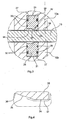
- eine vergrößerte Darstellung der Einzelheit III aus Fig. 1,
- Fig. 4
- eine vergrößerte Darstellung der Einzelheit IV aus Fig. 3 und
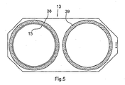
- Fig. 5
- eine Frontansicht des Schiebers.
- Der dargestellte Trennschieber weist ein Gehäuse 10 auf, das aus zwei Gehäusehälften 10a, 10b besteht, welche axial gegeneinander gesetzt und miteinander verschraubt sind. Die Gehäusehälften haben miteinander fluchtende Bohrungen, die einen Durchlass 11 bilden. An den Enden der Gehäusehälften befindet sich jeweils ein Flansch 12 zum Anflanschen einer Rohrleitung. Zwischen den Gehäusehälften ist ein länglicher Hohlraum gebildet, in dem ein plattenförmiger Schieber 13, der eine Öffnung 14 von etwa der selben Größe wie der Durchlass 11 aufweist, quer zur Achsrichtung des Gehäuses verschiebbar ist. Das Gehäuse 10 weist der Ebene des Schiebers 13 zwei nach entgegengesetzten Seiten abstehende Aufnahmeräume 15,16 auf, von denen jeweils einer eine Hälfte des Schiebers 13 aufnehmen kann, während sich die andere Hälfte in dem Gehäuse 10 befindet. An dem äußeren Ende des Aufnahmeraums 16 ist über Stangen 17 ein Pneumatikzylinder 18 befestigt, der einen Kolben 19 enthält. Der Pneumatikzylinder wird durch ein Ventil 20, das an eine (nicht dargestellte) Druckluftquelle angeschlossen ist, gesteuert. Mit dem Kolben 19 ist eine Kolbenstange 21 verbunden, welche in das Ende des Aufnahmeraumes 16 hineinragt und an ihrem anderen Ende mit dem Schieber 13 verbunden ist. Der Durchgang der Kolbenstange 21 durch die Endwand 22 des Aufnahmeraums 16 ist mit einer Stopfbuchsendichtung 23 abgedichtet.
- Bei dem vorliegenden Ausführungsbeispiel haben die Aufnahmeräume 15,16 Abschirmwände 24, um Wärmestrahlung von den Wänden des Trennschiebers fernzuhalten.
- In Figur 1 ist der Schieber 13 in seiner Absperrstellung dargestellt, in welcher sich die Öffnung 14 in dem Aufnahmeraum 15 befindet, während das Gehäuse 10 den geschlossenen Plattenbereich des Schiebers 13 enthält, welcher den Durchlass 11 versperrt. In dieser Schließstellung ist die Kolbenstange 21 aus dem Pneumatikzylinder 18 herausgefahren. Soll der Schieber 13 in die Öffnungsstellung gebracht werden, wird der Kolben 19 im Zylinder 18 zurückgefahren, so dass die Öffnung 14 des Schiebers 13 sich koaxial zu dem Durchlass 11 einstellt.
- Die Abdichtung des Durchlasses 11 zwischen Gehäuse 10 und Schieber 13 erfolgt durch zwei ringförmige Dichtungen 25,26, von denen jede in einer Gehäusehälfte 10a,10b enthalten ist. Zu diesem Zweck weist jede Gehäusehälfte einen ringförmigen Fluidzylinder 27 auf (Figur 3), der als axiale Nut in die Gehäusehälfte eingearbeitet ist. Jeder Fluidzylinder 27 enthält einen ringförmigen starren Dichtkörper 28, der einen Ringkolben bildet. Die Ringkolben 28 umgeben den Durchlass 11 auf jeder Seite des Schiebers 13. Jeder Dichtkörper 28 enthält an seiner Innenseite zwei Dichtringe 29 und an seiner Außenseite ebenfalls zwei Dichtringe 30 für die Abdichtung gegenüber dem pneumatischen ringförmigen Fluidzylinder 27. In jeden Fluidzylinder 27 führt am äußeren Ende 31 eine Druckleitung 32 bzw. 33 hinein, um den Dichtkörper 28 in Richtung auf den Schieber 13 vorzutreiben.
- Jeder Dichtkörper 28 weist an derjenigen Seite, die dem Schieber 13 zugewandt ist, eine Kontaktfläche 34 auf. Diese ist schmaler als die breite des Dichtkörpers, und sie geht über eine Schrägschulter 35 in einen zurückliegenden Bereich 36 über. Die ringscheibenförmige Kontaktfläche 34 befindet sich an dem Dichtkörper 28 an demjenigen Ende, das dem Durchlass 11 benachbart ist, während der Bereich 36 vom Durchlass entfernt ist.
- Die Kontaktfläche 34 ist mit einer Hartstoffschicht 37 beschichtet, die sich auch über einen Teil der Schrägschulter 35 erstreckt.
- Der Schieber 13 ist auf jeder seiner beiden Seiten ebenfalls mit zwei Hartstoffschichten 38,39 versehen (Figur 5). Diese Hartstoffschichten 38,39 sind ringförmige Scheiben. Die eine Hartstoffschicht 38 ist um die Öffnung 14 des Schiebers 13 herum angeordnet, und die andere Hartstoffschicht 39 ist um die Verschlussfläche des Schiebers angeordnet, die sich in dem Durchlass 11 des Gehäuses befindet, wenn der Schieber in der Schließstellung ist, wie dies in den Figuren 1 und 2 dargestellt ist.
- Die Hartstoffschichten 37,38,39 bestehen vorzugsweise aus Keramikmaterial, wie Chromdioxid, oder aus Hartmetall, wie Wolframkarbid. Im Anschluss an ihre Aufbringung sind sie durch Feinstbearbeitung behandelt, und zwar zunächst durch Schleifen und anschließend durch Honen oder Läppen. Die Rauhigkeit beträgt maximal Ra 4,was 4 µm entspricht. Insbesondere liegt sie im Bereich von Ra 0,4, also 0,4 µm, und darunter. Die Breite der Kontaktfläche 34 beträgt weniger als 10 mm und insbesondere etwa 5 mm. Sie sollte nicht größer sein als es für die Dichtwirkung erforderlich ist.
- Die Feinstbearbeitung der Oberflächen der Hartstoffschichten erfolgt durch paarweises Läppen, wobei zwei Hartstoffschichten aufeinandergelegt und aneinander gerieben werden. Diese beiden Hartstoffschichten sind diejenigen des Schiebers 13 und des zugehörigen Dichtkörpers. Diejenigen Hartstoffschichten, die später abdichtend gegeneinander liegen sollen, werden durch gegenseitiges Reiben bearbeitet, so dass die Hartstoffschichten paarweise zusammenpassen.
- Die Druckbeaufschlagung der Dichtkörper 28 erfolgt von dem Zylinder 18 aus. Von dem Steuerventil 20 führt eine Leitung 40 zu dem rückwärtigen Ende des Zylinders 18. Diese Leitung dient dazu, in dem Zylinder 18 eine auf den Kolben 19 wirkende Kraft zu erzeugen, die den Schieber 13 in die Schließposition treibt. Die Leitung 40 ist über weitere Leitungen 41,42,43 mit einem Verteiler 44 verbunden, an welchen die Leitungen 32 und 33 angeschlossen sind. Bei einer Druckbeaufschlagung des Zylinders 18 wird zunächst der Schieber 13 in die Schließstellung gebracht, und anschließend werden die Dichtkörper 28 von entgegengesetzten Seiten her gegen den Schieber gedrückt. Dieses Andrücken erfolgt nachgiebig. Dies bedeutet, dass die Dichtkörper 28 einer Verformung oder Verschiebung des Schiebers unter Aufrechterhaltung der Dichtwirkung folgen.
- Eine weitere Leitung 45, die von dem Ventil 20 aus in das vordere Ende des Zylinders 18 hineinführt, dient dazu, den Kolben 19 in die Rückzugsstellung zu bringen, wodurch der Schieber 13 in den Öffnungszustand bewegt wird.
- Der erfindungsgemäße Trennschieber ist für aggressive und abrasive Medien sowie auch für hohe Temperaturen geeignet. Der Rand der Öffnung 14 kann als Klinge ausgebildet sein, so dass etwaige Fremdkörper, die sich in der Öffnungsstellung des Schiebers festsetzen, beim Bewegen des Schiebers zerschnitten werden. Eine solche Klinge braucht nur an der dem Zylinder 18 zugewandten Hälfte der Öffnung 14 des Schiebers ausgebildet zu sein, während die andere Hälfte stumpf sein kann.
Claims (7)
- Trennschieber zum Absperren von Rohrleitungen, mit einem einen Durchlass (11) enthaltenen Schiebergehäuse (10), einem darin bewegbaren Schieber (13), der eine den Durchlass (11) freigebende Öffnung (14) aufweist, und ringförmigen Dichtkörpern (28), die um den Durchlass (11) herum im Schiebergehäuse (10) nachgiebig zu beiden Seiten des Schiebers (13) angeordnet sind, wobei die dem Schieber (13) zugewandten Kontaktflächen (34) der Dichtkörper (28) und die damit abdichtend zusammenwirkenden Kontaktflächen des Schiebers (13) aus Hartstoff bestehen und eine Oberflächenrauhigkeit von weniger als 10 µm haben,
dadurch gekennzeichnet,
dass die Kontaktflächen (34) Hartstoffschichten (37,38,39) sind, die härter sind als das Material des Schiebers (13), wobei der Schieber (13) imstande ist, sich quer zu der Schieberebene zu verformen. - Trennschieber nach Anspruch 1, dadurch gekennzeichnet, dass die Hartstoffschicht aus einem Carbid oder Oxid in keramischer oder metallischer Bindung besteht.
- Trennschieber nach Anspruch 1 oder 2, dadurch gekennzeichnet, dass die Hartstoffschichten eine Rauhigkeit von weniger als 4 µm haben.
- Trennschieber nach einem der Ansprüche 1 - 3, dadurch gekennzeichnet, dass die miteinander zusammenwirkenden Hartstoffschichten (37,38,39) von Schieber (13) und Dichtkörper (28) paarweise bearbeitet sind.
- Trennschieber nach einem der Ansprüche 1 - 4, dadurch gekennzeichnet, dass die Kontaktfläche (34) des Dichtkörpers (26) sich nur über einen Teil der Breite des Dichtkörpers erstreckt, wobei der übrige Bereich (36) der dem Schieber (13) zugewandten Fläche zurückliegend angeordnet ist.
- Trennschieber nach einem der Ansprüche 1 - 5, dadurch gekennzeichnet, dass die Fluidzylinder (27) entweder hydraulisch unter Einschaltung eines Gasdruckspeichers oder pneumatisch betrieben sind.
- Trennschieber nach einem der Ansprüche 1 - 6, dadurch gekennzeichnet, dass die Hartstoffschichten (38,39) des Schiebers (13) ringförmige Scheiben sind, von denen eine um die Öffnung (14) des Schiebers (13) herum und die andere um die Verschlussfläche des Schiebers herum angeordnet ist.
Applications Claiming Priority (2)
| Application Number | Priority Date | Filing Date | Title |
|---|---|---|---|
| DE20209420U | 2002-06-17 | ||
| DE20209420U DE20209420U1 (de) | 2002-06-17 | 2002-06-17 | Trennschieber |
Publications (2)
| Publication Number | Publication Date |
|---|---|
| EP1376000A1 EP1376000A1 (de) | 2004-01-02 |
| EP1376000B1 true EP1376000B1 (de) | 2006-08-23 |
Family
ID=7972282
Family Applications (1)
| Application Number | Title | Priority Date | Filing Date |
|---|---|---|---|
| EP03013507A Expired - Lifetime EP1376000B1 (de) | 2002-06-17 | 2003-06-13 | Trennschieber |
Country Status (4)
| Country | Link |
|---|---|
| US (1) | US7000899B2 (de) |
| EP (1) | EP1376000B1 (de) |
| AT (1) | ATE337513T1 (de) |
| DE (2) | DE20209420U1 (de) |
Cited By (1)
| Publication number | Priority date | Publication date | Assignee | Title |
|---|---|---|---|---|
| WO2011008728A1 (en) * | 2009-07-14 | 2011-01-20 | Delaware Capital Formation, Inc. | Vent with improved seal |
Families Citing this family (8)
| Publication number | Priority date | Publication date | Assignee | Title |
|---|---|---|---|---|
| CA2532571A1 (en) * | 2003-08-29 | 2005-03-10 | Rico-Sicherheitstechnik Ag | Sliding valve, in particular, quick-acting sliding valve for an explosion protection shut-off device |
| CA2544518A1 (en) * | 2005-04-21 | 2006-10-21 | Unverferth Manufacturing Company, Inc. | Direct double-acting in-line shut-off gate valve |
| DE202007006370U1 (de) | 2007-05-04 | 2007-07-12 | Bümach Engineering International B.V. | Oberflächenbeschichtete Maschinenelemente |
| BRPI0812458A2 (pt) * | 2007-06-11 | 2014-12-02 | Cameron Int Corp | " processo de revestimento de passagem ". |
| US9068657B2 (en) * | 2012-10-19 | 2015-06-30 | Varian Semiconductor Equipment Associates, Inc. | Gate valve with improved seal arrangement |
| DE102015110113B4 (de) | 2015-06-24 | 2018-06-14 | Burgmer Apparatebau GmbH | Absperrschieber |
| US9720425B2 (en) * | 2015-10-08 | 2017-08-01 | The Procter & Gamble Company | Low splash fluid shutoff valve assembly |
| DE102016107175B4 (de) | 2016-04-19 | 2025-02-06 | Z & J Technologies Gmbh | Absperrorgan für eine Ethylenherstellungsanlage |
Family Cites Families (11)
| Publication number | Priority date | Publication date | Assignee | Title |
|---|---|---|---|---|
| US3711062A (en) | 1970-11-02 | 1973-01-16 | C Kirkwood | Expandable seal gate valve |
| GB2083594A (en) * | 1980-07-26 | 1982-03-24 | Schubert & Salzer Maschinen | Slide valve |
| WO1985004460A1 (fr) * | 1984-04-03 | 1985-10-10 | Krohne Messtechnik Gmbh & Co. Kg | Organe d'arret et de reglage pour canalisations et autres avec une partie de fermeture en forme de coulisseau |
| DE3545266A1 (de) | 1985-12-20 | 1987-07-02 | B & S Metalpraecis Gmbh | Parallelschieber als absperr- und regelarmatur fuer gasfoermige und fluessige stoffstroeme |
| JPH01116386A (ja) | 1987-10-28 | 1989-05-09 | Kyocera Corp | セラミック摺動装置 |
| JPH01176862A (ja) | 1987-12-29 | 1989-07-13 | Kubota Ltd | 摺動特性にすぐれたバルブ部材 |
| US5370362A (en) | 1993-10-15 | 1994-12-06 | Abb Vetco Gray Inc. | Gate valve |
| DE9414158U1 (de) | 1994-09-01 | 1994-12-15 | Schweitzer, Karl-Friedrich, 40699 Erkrath | Flachschieber mit einer in einer Verschleißschutzmasse angebrachten O-Ringabdichtung |
| JP3217696B2 (ja) * | 1996-04-26 | 2001-10-09 | 京セラ株式会社 | ディスクバルブ |
| GB9813172D0 (en) * | 1998-06-19 | 1998-08-19 | Hart Robert | Gate Valve |
| US6454015B1 (en) * | 1999-07-15 | 2002-09-24 | Abb Vetco Gray Inc. | Shearing gate valve |
-
2002
- 2002-06-17 DE DE20209420U patent/DE20209420U1/de not_active Expired - Lifetime
-
2003
- 2003-06-13 AT AT03013507T patent/ATE337513T1/de active
- 2003-06-13 DE DE50304711T patent/DE50304711D1/de not_active Expired - Lifetime
- 2003-06-13 EP EP03013507A patent/EP1376000B1/de not_active Expired - Lifetime
- 2003-06-17 US US10/462,685 patent/US7000899B2/en not_active Expired - Fee Related
Cited By (1)
| Publication number | Priority date | Publication date | Assignee | Title |
|---|---|---|---|---|
| WO2011008728A1 (en) * | 2009-07-14 | 2011-01-20 | Delaware Capital Formation, Inc. | Vent with improved seal |
Also Published As
| Publication number | Publication date |
|---|---|
| ATE337513T1 (de) | 2006-09-15 |
| US20050167630A1 (en) | 2005-08-04 |
| EP1376000A1 (de) | 2004-01-02 |
| DE50304711D1 (de) | 2006-10-05 |
| US7000899B2 (en) | 2006-02-21 |
| DE20209420U1 (de) | 2002-11-21 |
Similar Documents
| Publication | Publication Date | Title |
|---|---|---|
| DE19746041A1 (de) | Steuerventil mit verbessertem Käfig | |
| DE69104193T2 (de) | Kugelventil. | |
| DE1288392B (de) | Drehschieber | |
| EP2985497B1 (de) | Verschlusselement für ein Vakuumventil mit abgepresster, aufvulkanisierter Dichtung | |
| DE102009051679A1 (de) | Ventilanordnung | |
| EP3258149A1 (de) | Vakuumventil zur regelung eines flusses und zur unterbrechung eines fliessweges | |
| DE3419999A1 (de) | Rohrverschraubung mit beruehrungsdichtung | |
| DE69113265T2 (de) | Schliessventilanordnung. | |
| EP0507127B1 (de) | Rohrweiche | |
| DE69503654T2 (de) | Rückschlagventil für hochdruck abrasiven schlamm | |
| DE102015110113B4 (de) | Absperrschieber | |
| EP1376000A1 (de) | Trennschieber | |
| DE3390493C2 (de) | ||
| DE102008017099B4 (de) | Flachschieber | |
| DE2639198C3 (de) | Absperrschieber | |
| CH662626A5 (de) | Schieberventilanordnung. | |
| EP1083994B1 (de) | Vorgespanntes steuerbares durchflussbegrenzungsventil, insbesondere sprühventil, und sprühbalken | |
| DE2059905C2 (de) | Verfahren und Vorrichtung zum Absperren des Strömungswegs in einer unter Druck stehenden Rohrleitung | |
| DE915764C (de) | Absperrorgan mit Kugelkueken | |
| DE20005776U1 (de) | Linearwegschieber | |
| DE3704244A1 (de) | Absperrschieber fuer rohrleitungen | |
| WO1985004460A1 (fr) | Organe d'arret et de reglage pour canalisations et autres avec une partie de fermeture en forme de coulisseau | |
| DE3303877C2 (de) | Einzelstempelventil | |
| DE9114696U1 (de) | Hochdruckhydraulikventil | |
| EP1645792B1 (de) | Anbohrvorrichtung |
Legal Events
| Date | Code | Title | Description |
|---|---|---|---|
| PUAI | Public reference made under article 153(3) epc to a published international application that has entered the european phase |
Free format text: ORIGINAL CODE: 0009012 |
|
| AK | Designated contracting states |
Kind code of ref document: A1 Designated state(s): AT BE BG CH CY CZ DE DK EE ES FI FR GB GR HU IE IT LI LU MC NL PT RO SE SI SK TR |
|
| AX | Request for extension of the european patent |
Extension state: AL LT LV MK |
|
| 17P | Request for examination filed |
Effective date: 20040623 |
|
| AKX | Designation fees paid |
Designated state(s): AT BE BG CH CY CZ DE DK EE ES FI FR GB GR HU IE IT LI LU MC NL PT RO SE SI SK TR |
|
| 17Q | First examination report despatched |
Effective date: 20040820 |
|
| GRAP | Despatch of communication of intention to grant a patent |
Free format text: ORIGINAL CODE: EPIDOSNIGR1 |
|
| GRAS | Grant fee paid |
Free format text: ORIGINAL CODE: EPIDOSNIGR3 |
|
| GRAA | (expected) grant |
Free format text: ORIGINAL CODE: 0009210 |
|
| AK | Designated contracting states |
Kind code of ref document: B1 Designated state(s): AT BE BG CH CY CZ DE DK EE ES FI FR GB GR HU IE IT LI LU MC NL PT RO SE SI SK TR |
|
| PG25 | Lapsed in a contracting state [announced via postgrant information from national office to epo] |
Ref country code: IT Free format text: LAPSE BECAUSE OF FAILURE TO SUBMIT A TRANSLATION OF THE DESCRIPTION OR TO PAY THE FEE WITHIN THE PRESCRIBED TIME-LIMIT;WARNING: LAPSES OF ITALIAN PATENTS WITH EFFECTIVE DATE BEFORE 2007 MAY HAVE OCCURRED AT ANY TIME BEFORE 2007. THE CORRECT EFFECTIVE DATE MAY BE DIFFERENT FROM THE ONE RECORDED. Effective date: 20060823 Ref country code: FI Free format text: LAPSE BECAUSE OF FAILURE TO SUBMIT A TRANSLATION OF THE DESCRIPTION OR TO PAY THE FEE WITHIN THE PRESCRIBED TIME-LIMIT Effective date: 20060823 Ref country code: RO Free format text: LAPSE BECAUSE OF FAILURE TO SUBMIT A TRANSLATION OF THE DESCRIPTION OR TO PAY THE FEE WITHIN THE PRESCRIBED TIME-LIMIT Effective date: 20060823 Ref country code: SK Free format text: LAPSE BECAUSE OF FAILURE TO SUBMIT A TRANSLATION OF THE DESCRIPTION OR TO PAY THE FEE WITHIN THE PRESCRIBED TIME-LIMIT Effective date: 20060823 Ref country code: SI Free format text: LAPSE BECAUSE OF FAILURE TO SUBMIT A TRANSLATION OF THE DESCRIPTION OR TO PAY THE FEE WITHIN THE PRESCRIBED TIME-LIMIT Effective date: 20060823 Ref country code: CZ Free format text: LAPSE BECAUSE OF FAILURE TO SUBMIT A TRANSLATION OF THE DESCRIPTION OR TO PAY THE FEE WITHIN THE PRESCRIBED TIME-LIMIT Effective date: 20060823 |
|
| REG | Reference to a national code |
Ref country code: GB Ref legal event code: FG4D Free format text: NOT ENGLISH |
|
| REG | Reference to a national code |
Ref country code: CH Ref legal event code: EP |
|
| REG | Reference to a national code |
Ref country code: IE Ref legal event code: FG4D Free format text: LANGUAGE OF EP DOCUMENT: GERMAN |
|
| REF | Corresponds to: |
Ref document number: 50304711 Country of ref document: DE Date of ref document: 20061005 Kind code of ref document: P |
|
| REG | Reference to a national code |
Ref country code: CH Ref legal event code: NV Representative=s name: ISLER & PEDRAZZINI AG |
|
| PG25 | Lapsed in a contracting state [announced via postgrant information from national office to epo] |
Ref country code: DK Free format text: LAPSE BECAUSE OF FAILURE TO SUBMIT A TRANSLATION OF THE DESCRIPTION OR TO PAY THE FEE WITHIN THE PRESCRIBED TIME-LIMIT Effective date: 20061123 Ref country code: SE Free format text: LAPSE BECAUSE OF FAILURE TO SUBMIT A TRANSLATION OF THE DESCRIPTION OR TO PAY THE FEE WITHIN THE PRESCRIBED TIME-LIMIT Effective date: 20061123 Ref country code: BG Free format text: LAPSE BECAUSE OF FAILURE TO SUBMIT A TRANSLATION OF THE DESCRIPTION OR TO PAY THE FEE WITHIN THE PRESCRIBED TIME-LIMIT Effective date: 20061123 |
|
| PG25 | Lapsed in a contracting state [announced via postgrant information from national office to epo] |
Ref country code: ES Free format text: LAPSE BECAUSE OF FAILURE TO SUBMIT A TRANSLATION OF THE DESCRIPTION OR TO PAY THE FEE WITHIN THE PRESCRIBED TIME-LIMIT Effective date: 20061204 |
|
| GBT | Gb: translation of ep patent filed (gb section 77(6)(a)/1977) |
Effective date: 20061127 |
|
| PG25 | Lapsed in a contracting state [announced via postgrant information from national office to epo] |
Ref country code: PT Free format text: LAPSE BECAUSE OF FAILURE TO SUBMIT A TRANSLATION OF THE DESCRIPTION OR TO PAY THE FEE WITHIN THE PRESCRIBED TIME-LIMIT Effective date: 20070125 |
|
| ET | Fr: translation filed | ||
| PLBE | No opposition filed within time limit |
Free format text: ORIGINAL CODE: 0009261 |
|
| STAA | Information on the status of an ep patent application or granted ep patent |
Free format text: STATUS: NO OPPOSITION FILED WITHIN TIME LIMIT |
|
| 26N | No opposition filed |
Effective date: 20070524 |
|
| REG | Reference to a national code |
Ref country code: CH Ref legal event code: PCAR Free format text: ISLER & PEDRAZZINI AG;POSTFACH 1772;8027 ZUERICH (CH) |
|
| PG25 | Lapsed in a contracting state [announced via postgrant information from national office to epo] |
Ref country code: MC Free format text: LAPSE BECAUSE OF NON-PAYMENT OF DUE FEES Effective date: 20070630 |
|
| PG25 | Lapsed in a contracting state [announced via postgrant information from national office to epo] |
Ref country code: GR Free format text: LAPSE BECAUSE OF FAILURE TO SUBMIT A TRANSLATION OF THE DESCRIPTION OR TO PAY THE FEE WITHIN THE PRESCRIBED TIME-LIMIT Effective date: 20061124 |
|
| PG25 | Lapsed in a contracting state [announced via postgrant information from national office to epo] |
Ref country code: EE Free format text: LAPSE BECAUSE OF FAILURE TO SUBMIT A TRANSLATION OF THE DESCRIPTION OR TO PAY THE FEE WITHIN THE PRESCRIBED TIME-LIMIT Effective date: 20060823 |
|
| PG25 | Lapsed in a contracting state [announced via postgrant information from national office to epo] |
Ref country code: LU Free format text: LAPSE BECAUSE OF NON-PAYMENT OF DUE FEES Effective date: 20070613 Ref country code: CY Free format text: LAPSE BECAUSE OF FAILURE TO SUBMIT A TRANSLATION OF THE DESCRIPTION OR TO PAY THE FEE WITHIN THE PRESCRIBED TIME-LIMIT Effective date: 20060823 |
|
| PG25 | Lapsed in a contracting state [announced via postgrant information from national office to epo] |
Ref country code: HU Free format text: LAPSE BECAUSE OF FAILURE TO SUBMIT A TRANSLATION OF THE DESCRIPTION OR TO PAY THE FEE WITHIN THE PRESCRIBED TIME-LIMIT Effective date: 20070224 Ref country code: TR Free format text: LAPSE BECAUSE OF FAILURE TO SUBMIT A TRANSLATION OF THE DESCRIPTION OR TO PAY THE FEE WITHIN THE PRESCRIBED TIME-LIMIT Effective date: 20060823 |
|
| REG | Reference to a national code |
Ref country code: NL Ref legal event code: V1 Effective date: 20110101 |
|
| REG | Reference to a national code |
Ref country code: NL Ref legal event code: BK Free format text: ONTERECHT VERVALLEN OP 01.01.2011PUBLIKATIE VERVAL I.E. 12.01.2011I.E. 2011/02 Effective date: 20060823 |
|
| PG25 | Lapsed in a contracting state [announced via postgrant information from national office to epo] |
Ref country code: NL Free format text: LAPSE BECAUSE OF NON-PAYMENT OF DUE FEES Effective date: 20110101 |
|
| PGFP | Annual fee paid to national office [announced via postgrant information from national office to epo] |
Ref country code: AT Payment date: 20121214 Year of fee payment: 10 |
|
| PGFP | Annual fee paid to national office [announced via postgrant information from national office to epo] |
Ref country code: IE Payment date: 20130628 Year of fee payment: 11 Ref country code: GB Payment date: 20130620 Year of fee payment: 11 Ref country code: CH Payment date: 20130621 Year of fee payment: 11 |
|
| PGFP | Annual fee paid to national office [announced via postgrant information from national office to epo] |
Ref country code: NL Payment date: 20130620 Year of fee payment: 11 |
|
| PGFP | Annual fee paid to national office [announced via postgrant information from national office to epo] |
Ref country code: BE Payment date: 20130627 Year of fee payment: 11 |
|
| PGFP | Annual fee paid to national office [announced via postgrant information from national office to epo] |
Ref country code: FR Payment date: 20130716 Year of fee payment: 11 |
|
| REG | Reference to a national code |
Ref country code: NL Ref legal event code: V1 Effective date: 20150101 |
|
| REG | Reference to a national code |
Ref country code: CH Ref legal event code: PL |
|
| REG | Reference to a national code |
Ref country code: AT Ref legal event code: MM01 Ref document number: 337513 Country of ref document: AT Kind code of ref document: T Effective date: 20140613 |
|
| GBPC | Gb: european patent ceased through non-payment of renewal fee |
Effective date: 20140613 |
|
| REG | Reference to a national code |
Ref country code: IE Ref legal event code: MM4A |
|
| REG | Reference to a national code |
Ref country code: FR Ref legal event code: ST Effective date: 20150227 |
|
| PG25 | Lapsed in a contracting state [announced via postgrant information from national office to epo] |
Ref country code: NL Free format text: LAPSE BECAUSE OF NON-PAYMENT OF DUE FEES Effective date: 20150101 |
|
| PG25 | Lapsed in a contracting state [announced via postgrant information from national office to epo] |
Ref country code: CH Free format text: LAPSE BECAUSE OF NON-PAYMENT OF DUE FEES Effective date: 20140630 Ref country code: IE Free format text: LAPSE BECAUSE OF NON-PAYMENT OF DUE FEES Effective date: 20140613 Ref country code: LI Free format text: LAPSE BECAUSE OF NON-PAYMENT OF DUE FEES Effective date: 20140630 |
|
| PGFP | Annual fee paid to national office [announced via postgrant information from national office to epo] |
Ref country code: DE Payment date: 20141218 Year of fee payment: 12 |
|
| PG25 | Lapsed in a contracting state [announced via postgrant information from national office to epo] |
Ref country code: FR Free format text: LAPSE BECAUSE OF NON-PAYMENT OF DUE FEES Effective date: 20140630 Ref country code: AT Free format text: LAPSE BECAUSE OF NON-PAYMENT OF DUE FEES Effective date: 20140613 Ref country code: GB Free format text: LAPSE BECAUSE OF NON-PAYMENT OF DUE FEES Effective date: 20140613 |
|
| REG | Reference to a national code |
Ref country code: DE Ref legal event code: R119 Ref document number: 50304711 Country of ref document: DE |
|
| PG25 | Lapsed in a contracting state [announced via postgrant information from national office to epo] |
Ref country code: DE Free format text: LAPSE BECAUSE OF NON-PAYMENT OF DUE FEES Effective date: 20160101 |
|
| PG25 | Lapsed in a contracting state [announced via postgrant information from national office to epo] |
Ref country code: BE Free format text: LAPSE BECAUSE OF NON-PAYMENT OF DUE FEES Effective date: 20140630 |