EP1375969A2 - Verfahren zum Herstellen eines Getriebeelementes - Google Patents
Verfahren zum Herstellen eines Getriebeelementes Download PDFInfo
- Publication number
- EP1375969A2 EP1375969A2 EP03009451A EP03009451A EP1375969A2 EP 1375969 A2 EP1375969 A2 EP 1375969A2 EP 03009451 A EP03009451 A EP 03009451A EP 03009451 A EP03009451 A EP 03009451A EP 1375969 A2 EP1375969 A2 EP 1375969A2
- Authority
- EP
- European Patent Office
- Prior art keywords
- ring element
- gear
- circumferential groove
- ring
- coupling body
- Prior art date
- Legal status (The legal status is an assumption and is not a legal conclusion. Google has not performed a legal analysis and makes no representation as to the accuracy of the status listed.)
- Granted
Links
Images

Classifications
-
- F—MECHANICAL ENGINEERING; LIGHTING; HEATING; WEAPONS; BLASTING
- F16—ENGINEERING ELEMENTS AND UNITS; GENERAL MEASURES FOR PRODUCING AND MAINTAINING EFFECTIVE FUNCTIONING OF MACHINES OR INSTALLATIONS; THERMAL INSULATION IN GENERAL
- F16H—GEARING
- F16H55/00—Elements with teeth or friction surfaces for conveying motion; Worms, pulleys or sheaves for gearing mechanisms
- F16H55/02—Toothed members; Worms
- F16H55/17—Toothed wheels
-
- B—PERFORMING OPERATIONS; TRANSPORTING
- B21—MECHANICAL METAL-WORKING WITHOUT ESSENTIALLY REMOVING MATERIAL; PUNCHING METAL
- B21K—MAKING FORGED OR PRESSED METAL PRODUCTS, e.g. HORSE-SHOES, RIVETS, BOLTS OR WHEELS
- B21K25/00—Uniting components to form integral members, e.g. turbine wheels and shafts, caulks with inserts, with or without shaping of the components
-
- B—PERFORMING OPERATIONS; TRANSPORTING
- B23—MACHINE TOOLS; METAL-WORKING NOT OTHERWISE PROVIDED FOR
- B23P—METAL-WORKING NOT OTHERWISE PROVIDED FOR; COMBINED OPERATIONS; UNIVERSAL MACHINE TOOLS
- B23P11/00—Connecting or disconnecting metal parts or objects by metal-working techniques not otherwise provided for
-
- F—MECHANICAL ENGINEERING; LIGHTING; HEATING; WEAPONS; BLASTING
- F16—ENGINEERING ELEMENTS AND UNITS; GENERAL MEASURES FOR PRODUCING AND MAINTAINING EFFECTIVE FUNCTIONING OF MACHINES OR INSTALLATIONS; THERMAL INSULATION IN GENERAL
- F16D—COUPLINGS FOR TRANSMITTING ROTATION; CLUTCHES; BRAKES
- F16D23/00—Details of mechanically-actuated clutches not specific for one distinct type
- F16D23/02—Arrangements for synchronisation, also for power-operated clutches
- F16D23/04—Arrangements for synchronisation, also for power-operated clutches with an additional friction clutch
- F16D23/06—Arrangements for synchronisation, also for power-operated clutches with an additional friction clutch and a blocking mechanism preventing the engagement of the main clutch prior to synchronisation
-
- F—MECHANICAL ENGINEERING; LIGHTING; HEATING; WEAPONS; BLASTING
- F16—ENGINEERING ELEMENTS AND UNITS; GENERAL MEASURES FOR PRODUCING AND MAINTAINING EFFECTIVE FUNCTIONING OF MACHINES OR INSTALLATIONS; THERMAL INSULATION IN GENERAL
- F16D—COUPLINGS FOR TRANSMITTING ROTATION; CLUTCHES; BRAKES
- F16D23/00—Details of mechanically-actuated clutches not specific for one distinct type
- F16D23/02—Arrangements for synchronisation, also for power-operated clutches
- F16D23/04—Arrangements for synchronisation, also for power-operated clutches with an additional friction clutch
- F16D23/06—Arrangements for synchronisation, also for power-operated clutches with an additional friction clutch and a blocking mechanism preventing the engagement of the main clutch prior to synchronisation
- F16D2023/0625—Details of members being coupled, e.g. gears
-
- F—MECHANICAL ENGINEERING; LIGHTING; HEATING; WEAPONS; BLASTING
- F16—ENGINEERING ELEMENTS AND UNITS; GENERAL MEASURES FOR PRODUCING AND MAINTAINING EFFECTIVE FUNCTIONING OF MACHINES OR INSTALLATIONS; THERMAL INSULATION IN GENERAL
- F16H—GEARING
- F16H55/00—Elements with teeth or friction surfaces for conveying motion; Worms, pulleys or sheaves for gearing mechanisms
- F16H55/02—Toothed members; Worms
- F16H55/17—Toothed wheels
- F16H55/171—Toothed belt pulleys
Definitions
- the present invention relates to a method for manufacturing a gear element with a gear wheel and a clutch body, in which the gear and the clutch body by means of a Circumferential teeth are coaxially and non-rotatably connected be so that they are free of play on the respective radial shoulders abut each other, one of the components of the gear or Coupling body in one opposite the radial shoulders Area in or adjacent to the circumferential teeth a circumferential groove has, in which a ring element made of a ductile Axial securing material is caulked.
- gear elements which by an assembly, consisting of a gear and a clutch body become.
- the gear can be an idler gear or a shift gear of the gearbox.
- gear elements In a second type of known gear elements are coupling bodies and gear wheel prefabricated as separate components and cohesively connected to one another via cylindrical surfaces.
- the non-rotatable and axially fixed connection is with this known transmission element achieved in that the by means of two elements in the area of their cylindrical fit of a laser welded.
- the weld seam is therefore axial through and must also go axially, because the high mentioned Torques must be transferable. It is therefore for this Welding process requires a high level of energy, reducing the components again become very warm and become undesirable deformation of the welded body can result.
- Gearwheels with coupling bodies are thus cohesive with one another connected that in turn a circumferential toothing to prevent rotation provides and the axial securing by resistance welding in the area of the end face. there becomes an annular copper electrode under pressure at the joint pressed between gear and clutch body.
- a fourth variant of known gear elements is the non-rotatable connection between the coupling body and gear reached by means of a circumferential toothing, which preferably as short teeth or as a spline profile is trained. It is usually located the internal teeth on the coupling body and the external teeth on the gear. However, it is also a reverse configuration conceivable in which the internal toothing on the gear and the External teeth on the coupling body.
- a fifth type of known gear element is manufactured by that a floating bearing of the coupling body the gear is provided in the axial direction.
- the clutch body is then axially supported on another gear element, e.g. a shift sleeve carrier.
- the invention is therefore based on the object of a method specify for the manufacture of a transmission element, which the existing in this very extensive state of the art Avoids disadvantages.
- This task is the Manufacture of a gear element solved in that the Ring element is first introduced into the circumferential groove, so that it is held captive in it, and that the ring element subsequently by means of a caulking tool against the circumferential groove non-exhibiting component is caulked.
- the introduction of the ring element can by means of a game or a press fit.
- a game fit is preferable, to be necessary after an interim quality check To be able to make changes with little effort.
- the ring element is when it is is held captive in the circumferential groove, including the gear and captively holds the clutch body together before that Ring element is caulked.
- the ring element is an open one Is ring element that spreads for insertion into the circumferential groove becomes.
- the Ring element in the form of a toroid.
- the ring element consists of a ductile Material consists, in particular of 20 MoCrS4 or one similar material.
- circumferential groove is by means of of a single tool simultaneously with an undercut on pierced opposite end of the circumferential toothing becomes.
- gear and the clutch body can be cured throughout without the need for Applying Condorsal or similar coatings before Hardening.
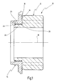
- 10 denotes a gear element of a motor vehicle multi-speed transmission.
- the gear element 10 consists essentially from a ratchet wheel 12 and a clutch body 14.
- Ratchet wheel 12 and clutch body 14 are fitted together and arranged coaxially to a common axis 16.
- the coupling body 14 is axially on the Shift wheel 12 pushed on until it has a radial shoulder 19 abuts a radial shoulder 18 of the ratchet wheel 12.
- gear element 10 instead of a ratchet wheel 12 also have a corresponding idler gear can and / or another arranged coaxially to the axis 16 Transmission component.
- a peripheral groove 30 is provided on the switching wheel 12, which is adjacent to the circumferential teeth 20, 22 opposite the shoulders 18, 19 is provided.
- the coupling body 14 is in the axial Direction with a radial shoulder 32 opposite the circumferential groove 30 before.
- a ring member 34 is inserted, so that it is held captive therein with play axially and radially.
- the ring element 34 lies in the axial direction with play between the radial shoulder 32 of the coupling body 14 and the opposite flank of the annular groove 30 of the ratchet wheel 12.
- the ratchet wheel 12, the clutch body 14 and the ring element 34 are therefore captively attached to one another in this state, however, there is still play in the axial direction.
- the ring element 34 is an open ring element made of a ductile Material, such as 20 MoCrS4, and passes through Spread open relatively easily into the circumferential groove 30.
- the Ring element 34 has the shape of a toroid, so has in the shown sectional view the shape of a circle. alternative could, for example, the ring element 34 in section be square, in particular square. Furthermore, it is conceivable that the ring member 34 is a closed ring member is.
- the radial groove 30 can simultaneously with the undercut 26 by means of a single tool can be attached to the ratchet 12, although this is not shown in the figures.
- ring element instead of a ring element, it is also conceivable to insert segments in Cold form pellets or balls. It is also conceivable a liquid instead of a prefabricated ring element pour into the annular groove 30, which then hardens. Also it is conceivable to introduce a sintered material which then is subjected to a sintering process.
Landscapes
- Engineering & Computer Science (AREA)
- Mechanical Engineering (AREA)
- General Engineering & Computer Science (AREA)
- Mechanical Operated Clutches (AREA)
- Forging (AREA)
Abstract
Description
- Fig. 1
- in schematischer Form einen Axialschnitt durch ein erfindungsgemäßes Getriebeelement;
- Fig. 2
- eine Detailansicht der Fig. 1 nach dem axialen Verbinden von Zahnrad und Kupplungskörper und nach dem Einsetzen eines Ringelementes in eine Umfangsnut vor einem Verstemmvorgang; und
- Fig. 3
- eine der Fig. 2 entsprechende Darstellung nach dem Verstemmen des Ringelementes.
Claims (7)
- Verfahren zum Herstellen eines Getriebeelementes (10) mit einem Zahnrad (12) und einem Kupplungskörper (14), bei dem das Zahnrad (12) und der Kupplungskörper (14) mittels einer Umfangsverzahnung (20, 22) koaxial und drehfest miteinander verbunden werden, so daß sie an jeweiligen Radialschultern (18, 19) spielfrei aneinander anliegen, wobei eines der Bauteile von Zahnrad (12) bzw. Kupplungskörper in einem den Radialschultern (18, 19) gegenüberliegenden Bereich in oder benachbart zu der Umfangsverzahnung (20, 22) eine Umfangsnut (30) aufweist, in die ein Ringelement (34) aus einem duktilen Material zur Axialsicherung verstemmt wird,
dadurch gekennzeichnet, daß
das Ringelement (34) zunächst in die Umfangsnut (30) eingebracht wird, so daß es unverlierbar darin gehalten ist, und daß das Ringelement (34) anschließend mittels eines Stemmwerkzeuges (36) gegen das die Umfangsnut (30) nicht aufweisende Bauelement (14) verstemmt wird. - Verfahren nach Anspruch 1, dadurch gekennzeichnet, daß das Ringelement (34), wenn es unverlierbar in der Umfangsnut (30) gehalten ist, auch das Zahnrad (12) und den Kupplungskörper (14) unverlierbar aneinander hält, bevor das Ringelement (34) verstemmt wird.
- Verfahren nach Anspruch 1 oder 2, dadurch gekennzeichnet, daß das Ringelement (34) ein offenes Ringelement (34) ist, das zum Einbringen in die Umfangsnut (30) aufgespreizt wird.
- Verfahren nach einem der Ansprüche 1- 3, dadurch gekennzeichnet, daß das Ringelement (34) die Form eines Toroids besitzt.
- Verfahren nach einem der Ansprüche 1 - 4, dadurch gekennzeichnet, daß das Ringelement (34) aus einem duktilen Werkstoff besteht, insbesondere aus 20 MoCrS4 oder einem ähnlichen Werkstoff.
- Verfahren nach einem der Ansprüche 1 - 5, dadurch gekennzeichnet, daß die Umfangsnut (30) mittels eines einzelnen Werkzeuges gleichzeitig mit einem Freistich (26) am gegenüberliegenden Ende der Umfangsverzahnung (20, 22) eingestochen wird.
- Verfahren nach einem der Ansprüche 1 - 6, dadurch gekennzeichnet, daß das Zahnrad (12) und der Kupplungskörper (14) gehärtet werden, bevor sie miteinander verbunden werden.
Applications Claiming Priority (2)
| Application Number | Priority Date | Filing Date | Title |
|---|---|---|---|
| DE10229682A DE10229682C1 (de) | 2002-06-26 | 2002-06-26 | Verfahren zum Herstellen eines Getriebeelementes |
| DE10229682 | 2002-06-26 |
Publications (3)
| Publication Number | Publication Date |
|---|---|
| EP1375969A2 true EP1375969A2 (de) | 2004-01-02 |
| EP1375969A3 EP1375969A3 (de) | 2005-06-22 |
| EP1375969B1 EP1375969B1 (de) | 2006-06-14 |
Family
ID=28685364
Family Applications (1)
| Application Number | Title | Priority Date | Filing Date |
|---|---|---|---|
| EP03009451A Expired - Lifetime EP1375969B1 (de) | 2002-06-26 | 2003-04-25 | Verfahren zum Herstellen eines Getriebeelementes |
Country Status (2)
| Country | Link |
|---|---|
| EP (1) | EP1375969B1 (de) |
| DE (1) | DE10229682C1 (de) |
Cited By (2)
| Publication number | Priority date | Publication date | Assignee | Title |
|---|---|---|---|---|
| US8016511B2 (en) | 2004-11-19 | 2011-09-13 | Miba Sinter Austria Gmbh | Metallic structural part joined from at least two components |
| EP2395255A2 (de) | 2010-06-09 | 2011-12-14 | ZF Friedrichshafen AG | Lösbare axiale Fixierung zweier Bauteile |
Families Citing this family (6)
| Publication number | Priority date | Publication date | Assignee | Title |
|---|---|---|---|---|
| DE102005060719A1 (de) * | 2005-12-19 | 2007-06-21 | Siemens Ag | Verfahren zum Verstemmen eines ersten Teiles |
| DE102006028286A1 (de) * | 2006-06-20 | 2007-12-27 | Wirsich, Konrad, Dipl.-Ing. (FH) | Drehmoment- und rutschfest verbundene aus zwei Teilen bestehende Schaltzahnräder |
| DE102009043367A1 (de) * | 2009-09-29 | 2011-04-07 | Gkn Sinter Metals Holding Gmbh | Anordnung eines Zahnrades und eines Kupplungskörpers zur Übertragung einer Drehbewegung |
| DE102010056178B4 (de) * | 2010-12-24 | 2021-02-11 | Daimler Ag | Verfahren zum Fügen eines Wellenteils mit einem Nabenteilersatz |
| DE102012217993C5 (de) * | 2012-10-02 | 2017-06-08 | Schaeffler Technologies AG & Co. KG | Kupplungskörper einer Synchronisationseinrichtung eines Kraftfahrzeug-Zahnräderwechselgetriebe und Verfahren zu seiner Herstellung |
| DE102012021496A1 (de) * | 2012-11-02 | 2014-05-08 | Volkswagen Aktiengesellschaft | Baueinheit für ein Fahrzeugwechselgetriebe mit verschweißtem Schaltrad und Kupplungskörper, sowie Schaltrad, Kupplungskörper, Fahrzeugwechselgetriebe und Verfahren zum Fügen von Schaltrad und Kupplungskörper durch Widerstandsschweißen |
Citations (2)
| Publication number | Priority date | Publication date | Assignee | Title |
|---|---|---|---|---|
| DE4228055C1 (de) | 1992-08-24 | 1994-03-03 | Keiper Recaro Gmbh Co | Stelleinrichtung für Fahrzeugsitze |
| DE19513992A1 (de) | 1995-04-13 | 1996-10-31 | Daimler Benz Ag | Axiale Fixierung einer Welle-Nabe-Verbindung |
Family Cites Families (5)
| Publication number | Priority date | Publication date | Assignee | Title |
|---|---|---|---|---|
| GB1204641A (en) * | 1969-04-08 | 1970-09-09 | Ford Motor Co | Transmission gears |
| US3750489A (en) * | 1972-06-07 | 1973-08-07 | Caterpillar Tractor Co | Composite drive assembly |
| DE4211186A1 (de) * | 1992-04-03 | 1993-10-07 | Krebsoege Gmbh Sintermetall | Verfahren insbesondere zur pulvermetallurgischen Herstellung eines Zahnrades mit einem Kupplungskörper |
| JPH11280788A (ja) * | 1998-03-27 | 1999-10-15 | Isuzu Motors Ltd | 変速機の同期装置 |
| FR2790052B1 (fr) * | 1999-02-18 | 2001-06-08 | Renault | Pignon fou pour boite de vitesses et procede pour sa fabrication |
-
2002
- 2002-06-26 DE DE10229682A patent/DE10229682C1/de not_active Expired - Fee Related
-
2003
- 2003-04-25 EP EP03009451A patent/EP1375969B1/de not_active Expired - Lifetime
Patent Citations (2)
| Publication number | Priority date | Publication date | Assignee | Title |
|---|---|---|---|---|
| DE4228055C1 (de) | 1992-08-24 | 1994-03-03 | Keiper Recaro Gmbh Co | Stelleinrichtung für Fahrzeugsitze |
| DE19513992A1 (de) | 1995-04-13 | 1996-10-31 | Daimler Benz Ag | Axiale Fixierung einer Welle-Nabe-Verbindung |
Cited By (3)
| Publication number | Priority date | Publication date | Assignee | Title |
|---|---|---|---|---|
| US8016511B2 (en) | 2004-11-19 | 2011-09-13 | Miba Sinter Austria Gmbh | Metallic structural part joined from at least two components |
| EP2395255A2 (de) | 2010-06-09 | 2011-12-14 | ZF Friedrichshafen AG | Lösbare axiale Fixierung zweier Bauteile |
| DE102010029863A1 (de) | 2010-06-09 | 2011-12-15 | Zf Friedrichshafen Ag | Lösbare axiale Fixierung zweier Bauteile |
Also Published As
| Publication number | Publication date |
|---|---|
| EP1375969B1 (de) | 2006-06-14 |
| DE10229682C1 (de) | 2003-10-30 |
| EP1375969A3 (de) | 2005-06-22 |
Similar Documents
| Publication | Publication Date | Title |
|---|---|---|
| WO2008046605A1 (de) | Einteiliges carrier für elektrischer parkbrems-aktuator mit planetengetriebe | |
| EP1989096B1 (de) | Schraubradgetriebe für zahnstangenlenkung | |
| EP2569555A1 (de) | Planetengetriebe mit verdrehsicherung | |
| WO2011029558A1 (de) | Übertragungsring für eine synchronisierungsbaugruppe für ein schaltgetriebe | |
| DE2036006C2 (de) | Wechselgetriebe insbesondere für Kraftfahrzeuge | |
| DE4211186A1 (de) | Verfahren insbesondere zur pulvermetallurgischen Herstellung eines Zahnrades mit einem Kupplungskörper | |
| DE102004008538B4 (de) | Differential mit einer Bolzenbefestigungsbaugruppe | |
| EP1375969B1 (de) | Verfahren zum Herstellen eines Getriebeelementes | |
| DE102007021194A1 (de) | Bauteil mit Innen- und Außenverzahnung | |
| EP3832171A1 (de) | Verfahren zur herstellung eines verbunds aus einem sonnenrad und einem planetenträger sowie verbund hergestellt nach diesem verfahren | |
| DE102019121275A1 (de) | Getriebeanordnung | |
| EP3339682B1 (de) | Schieberad für eine schaltgetriebeanordnung | |
| DE4302726C2 (de) | Zahnwellenverbindung und Verfahren zur Herstellung einer Zahnwellenverbindung | |
| DE19840466C2 (de) | Steckbare Antriebswelle, insbesondere für ein Kraftfahrzeug | |
| EP3938681A1 (de) | Differentialgetriebe | |
| DE2214577A1 (de) | Fahrzeuglenkung | |
| DE102013217755A1 (de) | Kupplungsanordnung, Kupplungselement sowie Verfahren zur Herstellung eines Kupplungselements | |
| DE10153653B4 (de) | Verfahren und Vorrichtung zum festen Verbinden zweier Konstruktionselemente | |
| DE102008040321B4 (de) | Ritzelbefestigung für Planetengetriebe | |
| EP3699442B1 (de) | Welle | |
| DE3626101A1 (de) | Drehbares antriebsbauteil fuer ein lenkgetriebe, insbesondere fuer kraftfahrzeuge | |
| DE2300851A1 (de) | Schraubengetriebe | |
| DE3423855A1 (de) | Radlagerung | |
| DE19931760A1 (de) | Gehäusekomponente und Reibflächenbaugruppe für eine hydrodynamische Kopplungseinrichtung und Verfahren zur Herstellung derselben | |
| DE4211769A1 (de) | Synchronisiereinrichtung fuer schaltkupplungen |
Legal Events
| Date | Code | Title | Description |
|---|---|---|---|
| PUAI | Public reference made under article 153(3) epc to a published international application that has entered the european phase |
Free format text: ORIGINAL CODE: 0009012 |
|
| AK | Designated contracting states |
Kind code of ref document: A2 Designated state(s): AT BE BG CH CY CZ DE DK EE ES FI FR GB GR HU IE IT LI LU MC NL PT RO SE SI SK TR |
|
| AX | Request for extension of the european patent |
Extension state: AL LT LV MK |
|
| PUAL | Search report despatched |
Free format text: ORIGINAL CODE: 0009013 |
|
| AK | Designated contracting states |
Kind code of ref document: A3 Designated state(s): AT BE BG CH CY CZ DE DK EE ES FI FR GB GR HU IE IT LI LU MC NL PT RO SE SI SK TR |
|
| AX | Request for extension of the european patent |
Extension state: AL LT LV MK |
|
| RIC1 | Information provided on ipc code assigned before grant |
Ipc: 7B 21K 25/00 B Ipc: 7F 16D 23/06 B Ipc: 7B 23P 11/00 B Ipc: 7F 16H 55/17 A |
|
| 17P | Request for examination filed |
Effective date: 20051008 |
|
| GRAP | Despatch of communication of intention to grant a patent |
Free format text: ORIGINAL CODE: EPIDOSNIGR1 |
|
| AKX | Designation fees paid |
Designated state(s): FR IT |
|
| GRAS | Grant fee paid |
Free format text: ORIGINAL CODE: EPIDOSNIGR3 |
|
| REG | Reference to a national code |
Ref country code: DE Ref legal event code: 8566 |
|
| GRAA | (expected) grant |
Free format text: ORIGINAL CODE: 0009210 |
|
| AK | Designated contracting states |
Kind code of ref document: B1 Designated state(s): FR IT |
|
| PG25 | Lapsed in a contracting state [announced via postgrant information from national office to epo] |
Ref country code: IT Free format text: LAPSE BECAUSE OF FAILURE TO SUBMIT A TRANSLATION OF THE DESCRIPTION OR TO PAY THE FEE WITHIN THE PRESCRIBED TIME-LIMIT;WARNING: LAPSES OF ITALIAN PATENTS WITH EFFECTIVE DATE BEFORE 2007 MAY HAVE OCCURRED AT ANY TIME BEFORE 2007. THE CORRECT EFFECTIVE DATE MAY BE DIFFERENT FROM THE ONE RECORDED. Effective date: 20060614 |
|
| ET | Fr: translation filed | ||
| PLBE | No opposition filed within time limit |
Free format text: ORIGINAL CODE: 0009261 |
|
| STAA | Information on the status of an ep patent application or granted ep patent |
Free format text: STATUS: NO OPPOSITION FILED WITHIN TIME LIMIT |
|
| 26N | No opposition filed |
Effective date: 20070315 |
|
| REG | Reference to a national code |
Ref country code: FR Ref legal event code: PLFP Year of fee payment: 14 |
|
| REG | Reference to a national code |
Ref country code: FR Ref legal event code: PLFP Year of fee payment: 15 |
|
| REG | Reference to a national code |
Ref country code: FR Ref legal event code: PLFP Year of fee payment: 16 |
|
| PGFP | Annual fee paid to national office [announced via postgrant information from national office to epo] |
Ref country code: FR Payment date: 20200420 Year of fee payment: 18 |
|
| PGFP | Annual fee paid to national office [announced via postgrant information from national office to epo] |
Ref country code: IT Payment date: 20200428 Year of fee payment: 18 |
|
| PG25 | Lapsed in a contracting state [announced via postgrant information from national office to epo] |
Ref country code: FR Free format text: LAPSE BECAUSE OF NON-PAYMENT OF DUE FEES Effective date: 20210430 |
|
| PG25 | Lapsed in a contracting state [announced via postgrant information from national office to epo] |
Ref country code: IT Free format text: LAPSE BECAUSE OF NON-PAYMENT OF DUE FEES Effective date: 20200425 |
|
| PG25 | Lapsed in a contracting state [announced via postgrant information from national office to epo] |
Ref country code: IT Free format text: LAPSE BECAUSE OF NON-PAYMENT OF DUE FEES Effective date: 20210425 |