EP1375855A1 - Dispositif de réduction de la signature visible et infrarouge d'un véhicule militaire - Google Patents
Dispositif de réduction de la signature visible et infrarouge d'un véhicule militaire Download PDFInfo
- Publication number
- EP1375855A1 EP1375855A1 EP03291551A EP03291551A EP1375855A1 EP 1375855 A1 EP1375855 A1 EP 1375855A1 EP 03291551 A EP03291551 A EP 03291551A EP 03291551 A EP03291551 A EP 03291551A EP 1375855 A1 EP1375855 A1 EP 1375855A1
- Authority
- EP
- European Patent Office
- Prior art keywords
- vehicle
- reducing
- visible
- box
- exhaust
- Prior art date
- Legal status (The legal status is an assumption and is not a legal conclusion. Google has not performed a legal analysis and makes no representation as to the accuracy of the status listed.)
- Granted
Links
Images
Classifications
-
- F—MECHANICAL ENGINEERING; LIGHTING; HEATING; WEAPONS; BLASTING
- F01—MACHINES OR ENGINES IN GENERAL; ENGINE PLANTS IN GENERAL; STEAM ENGINES
- F01N—GAS-FLOW SILENCERS OR EXHAUST APPARATUS FOR MACHINES OR ENGINES IN GENERAL; GAS-FLOW SILENCERS OR EXHAUST APPARATUS FOR INTERNAL COMBUSTION ENGINES
- F01N13/00—Exhaust or silencing apparatus characterised by constructional features ; Exhaust or silencing apparatus, or parts thereof, having pertinent characteristics not provided for in, or of interest apart from, groups F01N1/00 - F01N5/00, F01N9/00, F01N11/00
- F01N13/08—Other arrangements or adaptations of exhaust conduits
- F01N13/082—Other arrangements or adaptations of exhaust conduits of tailpipe, e.g. with means for mixing air with exhaust for exhaust cooling, dilution or evacuation
-
- F—MECHANICAL ENGINEERING; LIGHTING; HEATING; WEAPONS; BLASTING
- F01—MACHINES OR ENGINES IN GENERAL; ENGINE PLANTS IN GENERAL; STEAM ENGINES
- F01N—GAS-FLOW SILENCERS OR EXHAUST APPARATUS FOR MACHINES OR ENGINES IN GENERAL; GAS-FLOW SILENCERS OR EXHAUST APPARATUS FOR INTERNAL COMBUSTION ENGINES
- F01N3/00—Exhaust or silencing apparatus having means for purifying, rendering innocuous, or otherwise treating exhaust
- F01N3/02—Exhaust or silencing apparatus having means for purifying, rendering innocuous, or otherwise treating exhaust for cooling, or for removing solid constituents of, exhaust
- F01N3/05—Exhaust or silencing apparatus having means for purifying, rendering innocuous, or otherwise treating exhaust for cooling, or for removing solid constituents of, exhaust by means of air, e.g. by mixing exhaust with air
-
- F—MECHANICAL ENGINEERING; LIGHTING; HEATING; WEAPONS; BLASTING
- F41—WEAPONS
- F41H—ARMOUR; ARMOURED TURRETS; ARMOURED OR ARMED VEHICLES; MEANS OF ATTACK OR DEFENCE, e.g. CAMOUFLAGE, IN GENERAL
- F41H3/00—Camouflage, i.e. means or methods for concealment or disguise
-
- F—MECHANICAL ENGINEERING; LIGHTING; HEATING; WEAPONS; BLASTING
- F01—MACHINES OR ENGINES IN GENERAL; ENGINE PLANTS IN GENERAL; STEAM ENGINES
- F01P—COOLING OF MACHINES OR ENGINES IN GENERAL; COOLING OF INTERNAL-COMBUSTION ENGINES
- F01P11/00—Component parts, details, or accessories not provided for in, or of interest apart from, groups F01P1/00 - F01P9/00
- F01P11/12—Filtering, cooling, or silencing cooling-air
-
- Y—GENERAL TAGGING OF NEW TECHNOLOGICAL DEVELOPMENTS; GENERAL TAGGING OF CROSS-SECTIONAL TECHNOLOGIES SPANNING OVER SEVERAL SECTIONS OF THE IPC; TECHNICAL SUBJECTS COVERED BY FORMER USPC CROSS-REFERENCE ART COLLECTIONS [XRACs] AND DIGESTS
- Y02—TECHNOLOGIES OR APPLICATIONS FOR MITIGATION OR ADAPTATION AGAINST CLIMATE CHANGE
- Y02T—CLIMATE CHANGE MITIGATION TECHNOLOGIES RELATED TO TRANSPORTATION
- Y02T10/00—Road transport of goods or passengers
- Y02T10/10—Internal combustion engine [ICE] based vehicles
- Y02T10/12—Improving ICE efficiencies
Definitions
- the technical sector of the present invention is that of devices intended to reduce signatures visible and infrared of military vehicles, at the level of their exhaust and cooling gases.
- the evolution of camera and sensor technology can detect at great distances hot springs in the terrestrial environment, such exhaust and engine cooling of a vehicle. To improve stealth in the face of evolution infrared sensors, so it becomes necessary to reduce the level of energy radiated by the flux vehicle exhaust and cooling military.
- the object of the invention is precisely to improve the stealth of a military vehicle by masking of the emission zone, while maintaining protection the most effective ballistics possible.
- the present invention therefore relates to a device reduction of the visible and infrared signature of a military combat vehicle by dilution of gases engine exhaust and cooling air, characterized in that it comprises a box receiving the two sources of hot fluids to ensure an outlet unique exhaust and air from cooling.
- the box is made up an enclosure and a shutter at the level of its wall lateral external, the enclosure ensuring a homogeneous mixture of the two fluids and the shuttering constituting a means evacuation of this mixture.
- the box is provided a silencer and a dilution means connected to vehicle exhaust.
- a plate of shielding is arranged between the box and the box.
- the lengthening is designed to provide ballistic protection effective to the device.
- An application of the invention consists in placing the air outlet of the dilution device under the offset between two axles of the wheeled type vehicle.
- the exhaust system according to the invention makes it possible to produce a homogeneous mixture in cooled exhaust gas and air temperature ventilation without generating a ballistic protection hole.
- Another advantage is that protection vehicle ballistics and air evacuation are independent.
- Another advantage is that even when vehicle accelerations, smoke plume and heat is diluted, which reduces the detectability of the vehicle without reducing its performance.
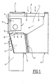
- Figure 1 is a schematic rear section representing the rear left part of the body of a military vehicle fitted with the device according to the invention.
- the invention is intended for military vehicles exposed to ballistic attacks.
- a vehicle armored vehicle type combat equipped with wheels This vehicle is equipped with a combustion engine (diesel engine by example). This type of motor produces significant heat, an engine cooling system is therefore provided for avoid overheating the engine.
- a combustion engine diesel engine by example.
- This type of motor produces significant heat, an engine cooling system is therefore provided for avoid overheating the engine.
- It is in particular the left rear part of body 11 of this vehicle which is schematically shown in Figure 1.
- the box dilution 1 is arranged at the rear of the body 11 of the military vehicle.
- the dilution chamber 1 is generally presented under the shape of a parallelepiped located in a free space, this space can, for example, be at the back of the vehicle, between two wheels, behind the last tire 6, or possibly, in the case of a vehicle with tracks, between two undercarriage rollers. It is composed of an enclosure 2 and a shutter 3 at the level of the outer side wall. Enclosure 2 communicates with two sources of hot fluids: the exhaust gases from vehicle and engine cooling air. Gas exhaust are evacuated from the engine by exhaust 5, then they go through a muffler 9 and through a means of dilution 10 before arriving in enclosure 2. The role of muffler 9 is to attenuate the noise coming from the engine. In the dilution means 10, a mixture of the exhaust gases is carried out with fresh air, in order to lower the temperature of these gases.
- Air for cooling the engine and other components comes from outside and enters a cooling enclosure 4 by a louver ballistics 8 arranged on the upper wall of the body of the vehicle 11.
- this cooling enclosure 4 is find the components to be cooled which can be example the engine of the vehicle or the fins of cooling in contact with temperature elements high (not shown in the diagram). Looks like engine cooling is then discharged to the dilution chamber 1. Exhaust gases and air from engine cooling mix in enclosure 2 before being evacuated by the persiennage 3.
- the persiennage 3, as well as the entire dilution chamber 1 can have light shielding, but this shielding is not imperative. Indeed, the box itself does not contain essential elements ensuring the proper functioning of the vehicle.
- shielding 27 provides protection between the vehicle body and the dilution chamber 1.
- a shield 17 replaces the old ones evacuation blinds which were placed at the level of the outer wall of the vehicle to complement and improve vehicle protection.
- case 1 If case 1 is destroyed, it is easily replaced without requiring intervention disassembly of the vehicle body.
- enclosure 2 can be placed in the vicinity of the gypsy, in front of or behind it, without significant changes to the principle described while retaining the advantages of the invention.
Landscapes
- Engineering & Computer Science (AREA)
- General Engineering & Computer Science (AREA)
- Chemical & Material Sciences (AREA)
- Combustion & Propulsion (AREA)
- Mechanical Engineering (AREA)
- Health & Medical Sciences (AREA)
- Chemical Kinetics & Catalysis (AREA)
- Toxicology (AREA)
- Cooling, Air Intake And Gas Exhaust, And Fuel Tank Arrangements In Propulsion Units (AREA)
- Aiming, Guidance, Guns With A Light Source, Armor, Camouflage, And Targets (AREA)
- Vehicle Interior And Exterior Ornaments, Soundproofing, And Insulation (AREA)
- Lighting Device Outwards From Vehicle And Optical Signal (AREA)
- Compositions Of Oxide Ceramics (AREA)
Abstract
Description
Claims (6)
- Dispositif de réduction de la signature visible et infrarouge d'un véhicule militaire par dilution des gaz d'échappement et de l'air de refroidissement de son moteur caractérisé en ce qu'il comprend un caisson (1) recevant les deux sources de fluides chauds pour assurer une sortie unique des gaz d'échappement et de l'air de refroidissement.
- Dispositif de réduction de la signature visible et infrarouge d'un véhicule selon la revendication 1, caractérisé en ce que le caisson (1) est constitué d'une enceinte (2) et d'un persiennage (3) au niveau de sa paroi latérale externe, l'enceinte assurant un mélange homogène des deux fluides et le persiennage constituant un moyen d'évacuation de ce mélange.
- Dispositif de réduction de la signature visible et infrarouge d'un véhicule selon la revendication 2, caractérisé en ce que le caisson (1) est muni d'un silencieux (9) et d'un moyen de dilution (10) connectés à l'échappement (5) du véhicule.
- Dispositif de réduction de la signature visible et infrarouge d'un véhicule selon la revendication 2 ou 3, caractérisé en ce qu'une plaque de blindage (27) est disposée entre le caisson (1) et la caisse (11).
- Dispositif de réduction de la signature visible et infrarouge d'un véhicule selon l'une des revendications 2 à 4, caractérisé en ce que le persiennage est réalisé de manière à assurer une protection balistique efficace au dispositif.
- Application du dispositif de réduction de la signature visible et infrarouge d'un véhicule selon l'une des revendications précédentes, caractérisé en ce que la sortie d'air se fait sous le déport entre deux essieux du véhicule du type à roues.
Applications Claiming Priority (2)
| Application Number | Priority Date | Filing Date | Title |
|---|---|---|---|
| FR0208062 | 2002-06-28 | ||
| FR0208062A FR2841594B1 (fr) | 2002-06-28 | 2002-06-28 | Dispositif de reduction de la signature visible et infrarouge d'un vehicule militaire |
Publications (2)
| Publication Number | Publication Date |
|---|---|
| EP1375855A1 true EP1375855A1 (fr) | 2004-01-02 |
| EP1375855B1 EP1375855B1 (fr) | 2006-10-25 |
Family
ID=29717127
Family Applications (1)
| Application Number | Title | Priority Date | Filing Date |
|---|---|---|---|
| EP03291551A Expired - Lifetime EP1375855B1 (fr) | 2002-06-28 | 2003-06-24 | Dispositif de réduction de la signature visible et infrarouge d'un véhicule militaire |
Country Status (6)
| Country | Link |
|---|---|
| US (1) | US7025165B2 (fr) |
| EP (1) | EP1375855B1 (fr) |
| AT (1) | ATE343713T1 (fr) |
| DE (1) | DE60309248T2 (fr) |
| ES (1) | ES2272918T3 (fr) |
| FR (1) | FR2841594B1 (fr) |
Cited By (1)
| Publication number | Priority date | Publication date | Assignee | Title |
|---|---|---|---|---|
| EP1574809A1 (fr) * | 2004-03-12 | 2005-09-14 | Rheinmetall Landsysteme GmbH | Dispositif de camouflage multispectral |
Families Citing this family (5)
| Publication number | Priority date | Publication date | Assignee | Title |
|---|---|---|---|---|
| US7482705B2 (en) * | 2003-05-12 | 2009-01-27 | Piercey Iii Gerald S | Generator support plenum |
| US20090071136A1 (en) * | 2007-09-14 | 2009-03-19 | Mack Trucks, Inc. | Exhaust diffuser for an internal combustion engine |
| JP5850024B2 (ja) * | 2013-10-31 | 2016-02-03 | コベルコ建機株式会社 | 作業機械 |
| CN104165081A (zh) * | 2014-07-21 | 2014-11-26 | 昆山晋桦豹胶轮车制造有限公司 | 防爆胶轮运输车尾气稀释装置 |
| US10245546B1 (en) | 2018-08-22 | 2019-04-02 | H & H Inventions & Enterprises, Inc. | Exhaust gas purification method and system |
Citations (6)
| Publication number | Priority date | Publication date | Assignee | Title |
|---|---|---|---|---|
| DE1099799B (de) * | 1959-04-14 | 1961-02-16 | Daimler Benz Ag | Auspuffleitung fuer Kraftwagen |
| DE3221378A1 (de) * | 1982-06-05 | 1983-12-08 | Rheinmetall GmbH, 4000 Düsseldorf | Gepanzertes fahrzeug |
| US4535862A (en) * | 1978-07-21 | 1985-08-20 | Leblanc James C | Engine cooling system for vehicles |
| FR2776705A1 (fr) * | 1998-03-26 | 1999-10-01 | Giat Ind Sa | Dispositif de dilution uniforme des gaz d'echappement d'un vehicule militaire |
| US6102791A (en) * | 1997-12-23 | 2000-08-15 | Steyr-Daimler-Puch Aktiengesellschaft | Cooling-air outlet for a vehicle |
| US6182440B1 (en) * | 1986-01-14 | 2001-02-06 | Northrop Grumman Corporation | Infrared radiation coanda suppressor |
Family Cites Families (8)
| Publication number | Priority date | Publication date | Assignee | Title |
|---|---|---|---|---|
| US4099375A (en) * | 1977-02-03 | 1978-07-11 | The United States Of America As Represented By The Secretary Of The Navy | Exhaust plume reduction and cooling system |
| DE2752729C1 (de) * | 1977-11-25 | 1983-06-09 | Pusch, Günter, Dr.-Ing., 6903 Neckargemünd | Verfahren und Anordnung zum Schutz in Betrieb befindlicher Fahrzeuge gegen Beobachtung durch Waermebildgeraete |
| US4215537A (en) * | 1978-07-27 | 1980-08-05 | Avco Corporation | Apparatus for and method of suppressing infrared radiation emitted from gas turbine engine |
| US4303035A (en) * | 1979-04-03 | 1981-12-01 | The United States Of America As Represented By The Secretary Of The Navy | Method of suppressing radiation from ship stack gases |
| DE3010598C2 (de) * | 1980-03-20 | 1984-05-24 | Deutsche Forschungs- und Versuchsanstalt für Luft- und Raumfahrt e.V., 5000 Köln | Durch Umgebungsluft gekühltes Abgasrohr |
| US4864819A (en) * | 1985-06-03 | 1989-09-12 | General Electric Company | Exhaust system including protective arrangements |
| US6055804A (en) * | 1997-07-23 | 2000-05-02 | Sikorsky Aircraft Corporation | Turning vane arrangement for IR suppressors |
| SE514268C2 (sv) * | 1998-12-04 | 2001-01-29 | Haegglunds Vehicle Ab | Avgasutsläpp med låg IR-signatur |
-
2002
- 2002-06-28 FR FR0208062A patent/FR2841594B1/fr not_active Expired - Fee Related
-
2003
- 2003-06-18 US US10/463,543 patent/US7025165B2/en not_active Expired - Fee Related
- 2003-06-24 DE DE60309248T patent/DE60309248T2/de not_active Expired - Lifetime
- 2003-06-24 ES ES03291551T patent/ES2272918T3/es not_active Expired - Lifetime
- 2003-06-24 EP EP03291551A patent/EP1375855B1/fr not_active Expired - Lifetime
- 2003-06-24 AT AT03291551T patent/ATE343713T1/de active
Patent Citations (6)
| Publication number | Priority date | Publication date | Assignee | Title |
|---|---|---|---|---|
| DE1099799B (de) * | 1959-04-14 | 1961-02-16 | Daimler Benz Ag | Auspuffleitung fuer Kraftwagen |
| US4535862A (en) * | 1978-07-21 | 1985-08-20 | Leblanc James C | Engine cooling system for vehicles |
| DE3221378A1 (de) * | 1982-06-05 | 1983-12-08 | Rheinmetall GmbH, 4000 Düsseldorf | Gepanzertes fahrzeug |
| US6182440B1 (en) * | 1986-01-14 | 2001-02-06 | Northrop Grumman Corporation | Infrared radiation coanda suppressor |
| US6102791A (en) * | 1997-12-23 | 2000-08-15 | Steyr-Daimler-Puch Aktiengesellschaft | Cooling-air outlet for a vehicle |
| FR2776705A1 (fr) * | 1998-03-26 | 1999-10-01 | Giat Ind Sa | Dispositif de dilution uniforme des gaz d'echappement d'un vehicule militaire |
Cited By (1)
| Publication number | Priority date | Publication date | Assignee | Title |
|---|---|---|---|---|
| EP1574809A1 (fr) * | 2004-03-12 | 2005-09-14 | Rheinmetall Landsysteme GmbH | Dispositif de camouflage multispectral |
Also Published As
| Publication number | Publication date |
|---|---|
| FR2841594B1 (fr) | 2006-12-15 |
| DE60309248D1 (de) | 2006-12-07 |
| US20050241874A1 (en) | 2005-11-03 |
| DE60309248T2 (de) | 2007-03-01 |
| EP1375855B1 (fr) | 2006-10-25 |
| ES2272918T3 (es) | 2007-05-01 |
| FR2841594A1 (fr) | 2004-01-02 |
| ATE343713T1 (de) | 2006-11-15 |
| US7025165B2 (en) | 2006-04-11 |
Similar Documents
| Publication | Publication Date | Title |
|---|---|---|
| CA1264951A (fr) | Systeme d'echappement a ecran protecteur | |
| FR2515735A1 (fr) | Dispositif de suppression de rayonnement infrarouge pour moteur a turbine a gaz | |
| FR2727506A1 (fr) | Dispositif de protection d'un vehicule ou d'une structure | |
| US20120003511A1 (en) | Lithium ion battery failure mitigation | |
| EP1375855A1 (fr) | Dispositif de réduction de la signature visible et infrarouge d'un véhicule militaire | |
| EP1831535A1 (fr) | Dispositif de captation d'air de combustion d'un moteur a combustion interne | |
| FR2922962A1 (fr) | Dispositif de recuperation et d'evacuation de produits de condensation d'un flux d'air d'admission | |
| WO1993018285A1 (fr) | Ligne d'echappement pour moteurs a combustion interne a deux temps | |
| EP0572643A1 (fr) | Tube douille pour grenade a fusil pouvant retenir les fragments de la balle. | |
| CA2997812C (fr) | Dispositif de piegeage de particules pour turbomachine et turbomachine equipee d'un tel dispositif | |
| RU2285888C2 (ru) | Способ защиты подвижного наземного объекта от обнаружения и поражения высокоточным оружием с инфракрасными головками самонаведения и экранирующее устройство для его реализации | |
| RU2673859C1 (ru) | Устройство снижения тепловой заметности боевых машин | |
| EP1502070B1 (fr) | Dispositif d'echappement avec ou sans dilution base sur deux sorties commandables | |
| KR101553905B1 (ko) | 전투차량 스텔스를 위한 배기가스 온도 저감 방안 및 그 장치 | |
| FR2907206A1 (fr) | Blindage actif avec capteurs infrarouges | |
| JPH08312335A (ja) | 排気微粒子処理装置 | |
| RU2750917C1 (ru) | Устройство снижения тепловой и акустической заметности легкобронированной техники | |
| FR3025002B1 (fr) | Conduit d'air pour le refroidissement d'un accessoire de vehicule automobile | |
| JP5013710B2 (ja) | 赤外線抑制装置及び方法 | |
| CN1254085A (zh) | 一种气囊式快速遮蔽防护装置 | |
| FR2863055A1 (fr) | Procede de detection de l'approche d'une cible, dispositif de detection et dispositif de protection mettant en oeuvre ce procede | |
| FR2508098A2 (fr) | Procede et dispositif de protection de vehicules mobiles contre l'observation par appareils a rayons infrarouges | |
| RU15601U1 (ru) | Кассетная боевая часть для блокирования линий электропередач | |
| RU2286475C2 (ru) | Ракетный двигатель твердого топлива | |
| WO2010052402A1 (fr) | Dispositif de refroidissement pour moteur a combustion interne |
Legal Events
| Date | Code | Title | Description |
|---|---|---|---|
| PUAI | Public reference made under article 153(3) epc to a published international application that has entered the european phase |
Free format text: ORIGINAL CODE: 0009012 |
|
| AK | Designated contracting states |
Kind code of ref document: A1 Designated state(s): AT BE BG CH CY CZ DE DK EE ES FI FR GB GR HU IE IT LI LU MC NL PT RO SE SI SK TR |
|
| AX | Request for extension of the european patent |
Extension state: AL LT LV MK |
|
| 17P | Request for examination filed |
Effective date: 20040120 |
|
| AKX | Designation fees paid |
Designated state(s): AT BE BG CH CY CZ DE DK EE ES FI FR GB GR HU IE IT LI LU MC NL PT RO SE SI SK TR |
|
| 17Q | First examination report despatched |
Effective date: 20050223 |
|
| GRAP | Despatch of communication of intention to grant a patent |
Free format text: ORIGINAL CODE: EPIDOSNIGR1 |
|
| GRAS | Grant fee paid |
Free format text: ORIGINAL CODE: EPIDOSNIGR3 |
|
| GRAA | (expected) grant |
Free format text: ORIGINAL CODE: 0009210 |
|
| AK | Designated contracting states |
Kind code of ref document: B1 Designated state(s): AT BE BG CH CY CZ DE DK EE ES FI FR GB GR HU IE IT LI LU MC NL PT RO SE SI SK TR |
|
| PG25 | Lapsed in a contracting state [announced via postgrant information from national office to epo] |
Ref country code: RO Free format text: LAPSE BECAUSE OF FAILURE TO SUBMIT A TRANSLATION OF THE DESCRIPTION OR TO PAY THE FEE WITHIN THE PRESCRIBED TIME-LIMIT Effective date: 20061025 Ref country code: SI Free format text: LAPSE BECAUSE OF FAILURE TO SUBMIT A TRANSLATION OF THE DESCRIPTION OR TO PAY THE FEE WITHIN THE PRESCRIBED TIME-LIMIT Effective date: 20061025 Ref country code: SK Free format text: LAPSE BECAUSE OF FAILURE TO SUBMIT A TRANSLATION OF THE DESCRIPTION OR TO PAY THE FEE WITHIN THE PRESCRIBED TIME-LIMIT Effective date: 20061025 Ref country code: NL Free format text: LAPSE BECAUSE OF FAILURE TO SUBMIT A TRANSLATION OF THE DESCRIPTION OR TO PAY THE FEE WITHIN THE PRESCRIBED TIME-LIMIT Effective date: 20061025 Ref country code: IE Free format text: LAPSE BECAUSE OF FAILURE TO SUBMIT A TRANSLATION OF THE DESCRIPTION OR TO PAY THE FEE WITHIN THE PRESCRIBED TIME-LIMIT Effective date: 20061025 Ref country code: CZ Free format text: LAPSE BECAUSE OF FAILURE TO SUBMIT A TRANSLATION OF THE DESCRIPTION OR TO PAY THE FEE WITHIN THE PRESCRIBED TIME-LIMIT Effective date: 20061025 |
|
| REG | Reference to a national code |
Ref country code: GB Ref legal event code: FG4D Free format text: NOT ENGLISH |
|
| REG | Reference to a national code |
Ref country code: CH Ref legal event code: EP |
|
| REG | Reference to a national code |
Ref country code: IE Ref legal event code: FG4D Free format text: LANGUAGE OF EP DOCUMENT: FRENCH |
|
| REF | Corresponds to: |
Ref document number: 60309248 Country of ref document: DE Date of ref document: 20061207 Kind code of ref document: P |
|
| GBT | Gb: translation of ep patent filed (gb section 77(6)(a)/1977) |
Effective date: 20061116 |
|
| PG25 | Lapsed in a contracting state [announced via postgrant information from national office to epo] |
Ref country code: DK Free format text: LAPSE BECAUSE OF FAILURE TO SUBMIT A TRANSLATION OF THE DESCRIPTION OR TO PAY THE FEE WITHIN THE PRESCRIBED TIME-LIMIT Effective date: 20070125 Ref country code: SE Free format text: LAPSE BECAUSE OF FAILURE TO SUBMIT A TRANSLATION OF THE DESCRIPTION OR TO PAY THE FEE WITHIN THE PRESCRIBED TIME-LIMIT Effective date: 20070125 Ref country code: BG Free format text: LAPSE BECAUSE OF FAILURE TO SUBMIT A TRANSLATION OF THE DESCRIPTION OR TO PAY THE FEE WITHIN THE PRESCRIBED TIME-LIMIT Effective date: 20070125 |
|
| PG25 | Lapsed in a contracting state [announced via postgrant information from national office to epo] |
Ref country code: PT Free format text: LAPSE BECAUSE OF FAILURE TO SUBMIT A TRANSLATION OF THE DESCRIPTION OR TO PAY THE FEE WITHIN THE PRESCRIBED TIME-LIMIT Effective date: 20070326 |
|
| NLV1 | Nl: lapsed or annulled due to failure to fulfill the requirements of art. 29p and 29m of the patents act | ||
| REG | Reference to a national code |
Ref country code: ES Ref legal event code: FG2A Ref document number: 2272918 Country of ref document: ES Kind code of ref document: T3 |
|
| REG | Reference to a national code |
Ref country code: IE Ref legal event code: FD4D |
|
| PLBE | No opposition filed within time limit |
Free format text: ORIGINAL CODE: 0009261 |
|
| STAA | Information on the status of an ep patent application or granted ep patent |
Free format text: STATUS: NO OPPOSITION FILED WITHIN TIME LIMIT |
|
| 26N | No opposition filed |
Effective date: 20070726 |
|
| BERE | Be: lapsed |
Owner name: GIAT INDUSTRIES Effective date: 20070630 |
|
| PG25 | Lapsed in a contracting state [announced via postgrant information from national office to epo] |
Ref country code: MC Free format text: LAPSE BECAUSE OF NON-PAYMENT OF DUE FEES Effective date: 20070630 |
|
| REG | Reference to a national code |
Ref country code: CH Ref legal event code: PL |
|
| PG25 | Lapsed in a contracting state [announced via postgrant information from national office to epo] |
Ref country code: BE Free format text: LAPSE BECAUSE OF NON-PAYMENT OF DUE FEES Effective date: 20070630 |
|
| PG25 | Lapsed in a contracting state [announced via postgrant information from national office to epo] |
Ref country code: GR Free format text: LAPSE BECAUSE OF FAILURE TO SUBMIT A TRANSLATION OF THE DESCRIPTION OR TO PAY THE FEE WITHIN THE PRESCRIBED TIME-LIMIT Effective date: 20070126 Ref country code: LI Free format text: LAPSE BECAUSE OF NON-PAYMENT OF DUE FEES Effective date: 20070630 Ref country code: CH Free format text: LAPSE BECAUSE OF NON-PAYMENT OF DUE FEES Effective date: 20070630 |
|
| PG25 | Lapsed in a contracting state [announced via postgrant information from national office to epo] |
Ref country code: EE Free format text: LAPSE BECAUSE OF FAILURE TO SUBMIT A TRANSLATION OF THE DESCRIPTION OR TO PAY THE FEE WITHIN THE PRESCRIBED TIME-LIMIT Effective date: 20061025 |
|
| REG | Reference to a national code |
Ref country code: GB Ref legal event code: 732E Free format text: REGISTERED BETWEEN 20090625 AND 20090701 |
|
| PG25 | Lapsed in a contracting state [announced via postgrant information from national office to epo] |
Ref country code: CY Free format text: LAPSE BECAUSE OF FAILURE TO SUBMIT A TRANSLATION OF THE DESCRIPTION OR TO PAY THE FEE WITHIN THE PRESCRIBED TIME-LIMIT Effective date: 20061025 Ref country code: LU Free format text: LAPSE BECAUSE OF NON-PAYMENT OF DUE FEES Effective date: 20070624 |
|
| PG25 | Lapsed in a contracting state [announced via postgrant information from national office to epo] |
Ref country code: HU Free format text: LAPSE BECAUSE OF FAILURE TO SUBMIT A TRANSLATION OF THE DESCRIPTION OR TO PAY THE FEE WITHIN THE PRESCRIBED TIME-LIMIT Effective date: 20070426 |
|
| PGFP | Annual fee paid to national office [announced via postgrant information from national office to epo] |
Ref country code: GB Payment date: 20150527 Year of fee payment: 13 Ref country code: FI Payment date: 20150522 Year of fee payment: 13 Ref country code: ES Payment date: 20150605 Year of fee payment: 13 Ref country code: TR Payment date: 20150616 Year of fee payment: 13 |
|
| PGFP | Annual fee paid to national office [announced via postgrant information from national office to epo] |
Ref country code: IT Payment date: 20150529 Year of fee payment: 13 Ref country code: AT Payment date: 20150522 Year of fee payment: 13 |
|
| REG | Reference to a national code |
Ref country code: ES Ref legal event code: PC2A Owner name: NEXTER SYTEMS Effective date: 20160315 |
|
| REG | Reference to a national code |
Ref country code: FR Ref legal event code: PLFP Year of fee payment: 14 |
|
| REG | Reference to a national code |
Ref country code: AT Ref legal event code: PC Ref document number: 343713 Country of ref document: AT Kind code of ref document: T Owner name: NEXTER SYSTEMS, FR Effective date: 20160725 |
|
| PG25 | Lapsed in a contracting state [announced via postgrant information from national office to epo] |
Ref country code: FI Free format text: LAPSE BECAUSE OF NON-PAYMENT OF DUE FEES Effective date: 20160624 |
|
| REG | Reference to a national code |
Ref country code: AT Ref legal event code: MM01 Ref document number: 343713 Country of ref document: AT Kind code of ref document: T Effective date: 20160624 |
|
| GBPC | Gb: european patent ceased through non-payment of renewal fee |
Effective date: 20160624 |
|
| REG | Reference to a national code |
Ref country code: FR Ref legal event code: PLFP Year of fee payment: 15 |
|
| PG25 | Lapsed in a contracting state [announced via postgrant information from national office to epo] |
Ref country code: AT Free format text: LAPSE BECAUSE OF NON-PAYMENT OF DUE FEES Effective date: 20160624 Ref country code: GB Free format text: LAPSE BECAUSE OF NON-PAYMENT OF DUE FEES Effective date: 20160624 |
|
| PG25 | Lapsed in a contracting state [announced via postgrant information from national office to epo] |
Ref country code: IT Free format text: LAPSE BECAUSE OF NON-PAYMENT OF DUE FEES Effective date: 20160624 |
|
| REG | Reference to a national code |
Ref country code: FR Ref legal event code: PLFP Year of fee payment: 16 |
|
| PG25 | Lapsed in a contracting state [announced via postgrant information from national office to epo] |
Ref country code: ES Free format text: LAPSE BECAUSE OF NON-PAYMENT OF DUE FEES Effective date: 20160625 |
|
| REG | Reference to a national code |
Ref country code: ES Ref legal event code: FD2A Effective date: 20181203 |
|
| PGFP | Annual fee paid to national office [announced via postgrant information from national office to epo] |
Ref country code: DE Payment date: 20190521 Year of fee payment: 17 |
|
| PGFP | Annual fee paid to national office [announced via postgrant information from national office to epo] |
Ref country code: FR Payment date: 20190522 Year of fee payment: 17 |
|
| REG | Reference to a national code |
Ref country code: DE Ref legal event code: R119 Ref document number: 60309248 Country of ref document: DE |
|
| PG25 | Lapsed in a contracting state [announced via postgrant information from national office to epo] |
Ref country code: FR Free format text: LAPSE BECAUSE OF NON-PAYMENT OF DUE FEES Effective date: 20200630 |
|
| PG25 | Lapsed in a contracting state [announced via postgrant information from national office to epo] |
Ref country code: DE Free format text: LAPSE BECAUSE OF NON-PAYMENT OF DUE FEES Effective date: 20210101 |
|
| PG25 | Lapsed in a contracting state [announced via postgrant information from national office to epo] |
Ref country code: TR Free format text: LAPSE BECAUSE OF NON-PAYMENT OF DUE FEES Effective date: 20160624 |
|
| P01 | Opt-out of the competence of the unified patent court (upc) registered |
Effective date: 20230601 |