EP1375813B1 - Beheizbares Beschattungssystem - Google Patents
Beheizbares Beschattungssystem Download PDFInfo
- Publication number
- EP1375813B1 EP1375813B1 EP03014321A EP03014321A EP1375813B1 EP 1375813 B1 EP1375813 B1 EP 1375813B1 EP 03014321 A EP03014321 A EP 03014321A EP 03014321 A EP03014321 A EP 03014321A EP 1375813 B1 EP1375813 B1 EP 1375813B1
- Authority
- EP
- European Patent Office
- Prior art keywords
- pane
- individual
- shading system
- space
- inter
- Prior art date
- Legal status (The legal status is an assumption and is not a legal conclusion. Google has not performed a legal analysis and makes no representation as to the accuracy of the status listed.)
- Expired - Lifetime
Links
- 238000010438 heat treatment Methods 0.000 claims description 21
- 238000000576 coating method Methods 0.000 claims description 10
- 239000011248 coating agent Substances 0.000 claims description 9
- 238000005485 electric heating Methods 0.000 claims description 2
- 239000011521 glass Substances 0.000 claims description 2
- 229920005989 resin Polymers 0.000 claims description 2
- 239000011347 resin Substances 0.000 claims description 2
- XOLBLPGZBRYERU-UHFFFAOYSA-N tin dioxide Chemical compound O=[Sn]=O XOLBLPGZBRYERU-UHFFFAOYSA-N 0.000 claims description 2
- 229910001887 tin oxide Inorganic materials 0.000 claims description 2
- 230000003019 stabilising effect Effects 0.000 claims 3
- PXGOKWXKJXAPGV-UHFFFAOYSA-N Fluorine Chemical compound FF PXGOKWXKJXAPGV-UHFFFAOYSA-N 0.000 claims 1
- 229910052731 fluorine Inorganic materials 0.000 claims 1
- 239000011737 fluorine Substances 0.000 claims 1
- 229910052738 indium Inorganic materials 0.000 claims 1
- APFVFJFRJDLVQX-UHFFFAOYSA-N indium atom Chemical compound [In] APFVFJFRJDLVQX-UHFFFAOYSA-N 0.000 claims 1
- 229920002994 synthetic fiber Polymers 0.000 claims 1
- 230000008901 benefit Effects 0.000 description 5
- 229920002037 poly(vinyl butyral) polymer Polymers 0.000 description 4
- 238000010276 construction Methods 0.000 description 3
- 239000007789 gas Substances 0.000 description 3
- 239000005340 laminated glass Substances 0.000 description 3
- 125000006850 spacer group Chemical group 0.000 description 3
- XKRFYHLGVUSROY-UHFFFAOYSA-N Argon Chemical compound [Ar] XKRFYHLGVUSROY-UHFFFAOYSA-N 0.000 description 2
- 238000000034 method Methods 0.000 description 2
- 230000005855 radiation Effects 0.000 description 2
- 239000005336 safety glass Substances 0.000 description 2
- 230000000087 stabilizing effect Effects 0.000 description 2
- 229910018503 SF6 Inorganic materials 0.000 description 1
- 229910052786 argon Inorganic materials 0.000 description 1
- -1 argon (Ar) Chemical class 0.000 description 1
- 239000002131 composite material Substances 0.000 description 1
- 238000009833 condensation Methods 0.000 description 1
- 230000005494 condensation Effects 0.000 description 1
- 238000011161 development Methods 0.000 description 1
- 230000018109 developmental process Effects 0.000 description 1
- 239000003814 drug Substances 0.000 description 1
- 239000000428 dust Substances 0.000 description 1
- 230000000694 effects Effects 0.000 description 1
- 238000005516 engineering process Methods 0.000 description 1
- 239000005329 float glass Substances 0.000 description 1
- 239000011261 inert gas Substances 0.000 description 1
- 238000009413 insulation Methods 0.000 description 1
- 229910052743 krypton Inorganic materials 0.000 description 1
- DNNSSWSSYDEUBZ-UHFFFAOYSA-N krypton atom Chemical compound [Kr] DNNSSWSSYDEUBZ-UHFFFAOYSA-N 0.000 description 1
- 238000001755 magnetron sputter deposition Methods 0.000 description 1
- 238000004519 manufacturing process Methods 0.000 description 1
- 238000004377 microelectronic Methods 0.000 description 1
- 239000000203 mixture Substances 0.000 description 1
- 229910052756 noble gas Inorganic materials 0.000 description 1
- 150000002835 noble gases Chemical class 0.000 description 1
- 239000002245 particle Substances 0.000 description 1
- 229920003023 plastic Polymers 0.000 description 1
- 239000010970 precious metal Substances 0.000 description 1
- 230000001681 protective effect Effects 0.000 description 1
- 238000007789 sealing Methods 0.000 description 1
- SFZCNBIFKDRMGX-UHFFFAOYSA-N sulfur hexafluoride Chemical compound FS(F)(F)(F)(F)F SFZCNBIFKDRMGX-UHFFFAOYSA-N 0.000 description 1
- 229960000909 sulfur hexafluoride Drugs 0.000 description 1
- 238000007669 thermal treatment Methods 0.000 description 1
- 230000036642 wellbeing Effects 0.000 description 1
- 229910052724 xenon Inorganic materials 0.000 description 1
- FHNFHKCVQCLJFQ-UHFFFAOYSA-N xenon atom Chemical compound [Xe] FHNFHKCVQCLJFQ-UHFFFAOYSA-N 0.000 description 1
Images
Classifications
-
- E—FIXED CONSTRUCTIONS
- E06—DOORS, WINDOWS, SHUTTERS, OR ROLLER BLINDS IN GENERAL; LADDERS
- E06B—FIXED OR MOVABLE CLOSURES FOR OPENINGS IN BUILDINGS, VEHICLES, FENCES OR LIKE ENCLOSURES IN GENERAL, e.g. DOORS, WINDOWS, BLINDS, GATES
- E06B9/00—Screening or protective devices for wall or similar openings, with or without operating or securing mechanisms; Closures of similar construction
- E06B9/24—Screens or other constructions affording protection against light, especially against sunshine; Similar screens for privacy or appearance; Slat blinds
- E06B9/26—Lamellar or like blinds, e.g. venetian blinds
- E06B9/264—Combinations of lamellar blinds with roller shutters, screen windows, windows, or double panes; Lamellar blinds with special devices
Definitions
- the invention relates to a shading system according to the preamble of claim 1.
- glazing systems are increasingly being used, which take on demanding tasks beyond the mere glazing function.
- an increasing effort has been made to use glazing systems for space heating during the winter months and during the transitional period.
- EP 0 984 131 A discloses a shading system according to the preamble of claim 1.
- An inventive shading system comprises an inner disc and an outer disc, which form a first disc space, and arranged in the first disc space slatted blind with pivotable about its longitudinal axis and optionally additionally raised and lowered slats with which the interior of a room is shaded. At least one of the discs - preferably the inner disc - is provided with an electric heater.
- the slats are pivotable and optionally additionally raised and lowered.
- This design takes into account the fact that in practice practically every user of a blind wishes pivotable slats whose lifting and lowering ability is only required in about 70 to 80% of the applications.
- a state of maximum shading results if its plate pack is extended downwards and the individual plates are turned against the sun.
- the shading can be selectively reduced until the slats are horizontal. Starting from this state, a start-up of the slats only results in a slight further decrease in shading, which usually does not matter in practice.
- a ramp-up of the slats usually has only the aesthetic benefit that the horizontal slats disappear from the field of vision.
- the inner pane is made up of two individual panes, with a single pane adjoining the shadable space and the other single pane adjacent to the first pane spacing, and the individual panes being connected to a laminated glass unit with a bonding layer disposed therebetween.
- the heating takes place in this embodiment by embedded in the connecting layer electrical Heating wires.
- the individual discs with the connecting layer and the heating wires are connected to each other so that they are practically invisible to the naked eye.
- the production takes place by stacking elastic films, preferably of PVB (polyvinyl butyral), in which heating wires are embedded, and slices of float glass and a subsequent thermal treatment of this composite under pressure in an autoclave.
- Safety-relevant is the property of laminated glass to not break into small pieces when impacted. Although occurring jumps run over the affected individual disc, the inner disc is held together by the connecting layer and remains in their overall structure.
- a stabilizing element may be arranged between the individual panes, preferably in the form of a layer of transparent hardened cast resin or of transparent plastic, for example of PVB (polyvinyl butyral). This layer connects the two individual panes and expands the system of laminated safety glass.
- the individual disks can also be spaced apart from one another and form a second space between the panes.
- the heating takes place by means of an electrically conductive surface coating which is applied to that surface of the single pane adjoining the shadable space, which adjoins the second space between the panes.
- the surface coating is preferably a hard coating of fluorine-doped or indium-doped tin oxide.
- a stabilizing element can be arranged between the individual disks, wherein a completely or partially circumferential spacer is preferred.
- the surface of the outer disk adjacent the first disk space may carry a heat-reflecting layer.
- This embodiment is particularly preferred because it prevents heat losses by radiation to the outside.
- the energy generated by the electric heater is largely completely supplied to the shadable space.
- the use of this energy is 90% or more. Preference is given to soft coatings based on precious metals, which are produced by the magnetron sputtering process.
- gas and “gas-tight” should in the context of this description and in the protection claims relate both to normal atmospheric air and inert gases, which are used in the glazing technique for heat and / or sound insulation.
- protective gases are noble gases such as argon (Ar), krypton (Kr) and xenon (Xe) and sulfur hexafluoride (SF 6 ) or mixtures thereof.
- Another advantage is the ability to influence the climatic conditions by installing a system according to the invention as a window or in a facade.
- the internal venetian blind can control the heat and light flow.
- the internal venetian blind can control the heat and light flow.
- the nursing months and in the Gögangsproofperiode can be generated with the heated disc heat, their fast availability has already been mentioned.
- the transitional heating period is especially an additional heating in question. This heat is available in the building, where traditionally the largest heat losses occur.
- the disc heating prevents the condensation of moisture and misting of the glass surfaces.
- the heat energy generated arises as pure heat radiation and reaches the space either directly or after reflection at the preferably used heat-reflecting layer of the outer pane. Convection is therefore largely dispensed with.
- the heating is therefore practically without drafts and without transport of dust particles and makes a contribution to the room hygiene. This effect is particularly important in the field of medicine, for example in operating rooms, sterile rooms and medical practices. He also plays a role in clean rooms in which microelectronic products are manufactured.
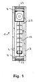
- Fig. 1 shows the basic structure of the shading system 1 according to the invention in section (hereafter "system”). Shown are the venetian blind 12 with the slats 13, which is arranged between two panes 2, 3. Disc 2 forms the inner, disc 3, the outer disc. The Venetian blind 12 is taken by a spacer 4, which consists of four pieces. These form a first interpane space 22. Shown in Fig. 1 also a seal 23, which extends around all four sides of the discs 2, 3 and the system gas-tight.
- system Shown are the venetian blind 12 with the slats 13, which is arranged between two panes 2, 3. Disc 2 forms the inner, disc 3, the outer disc. The Venetian blind 12 is taken by a spacer 4, which consists of four pieces. These form a first interpane space 22. Shown in Fig. 1 also a seal 23, which extends around all four sides of the discs 2, 3 and the system gas-tight.
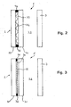
- Fig. 2 shows a schematic representation of the heating of the shading system according to the invention according to a first embodiment.
- the inner pane 2 is made up of two individual panes 30, 31, wherein the single pane 30 adjoins the shadable space and the other single pane 31 adjoins the first pan space 22.
- the shadable space is located to the left of the inner pane 2.
- the individual panes 30, 31 are connected to a connecting layer 33 arranged between them to form a laminated glass unit. To simplify the drawing, further details such as the Venetian blind 12, fins 13 and the like. Not shown.
- the heating takes place by electric heating wires 32, which are embedded in the connecting layer 33. So it is the inner pane 2 heated.
- Fig. 3 shows a schematic representation of the heating of the shading system according to the invention according to a second embodiment of the shading system according to the invention.
- the inner disc 2 of two individual discs 30, 31 constructed.
- a single disk 30 in turn adjoins the shadable space and the other individual disk 31 to the first disc space 22.
- the shadable space is also located to the left of the inner pane 2.
- the individual panes 30, 31 are here spaced from each other and form a second space between the panes 35th
- the heating is effected by an electrically conductive surface coating 34. This is applied to a surface of the adjoining the shadable space single disc 30, on the surface adjacent to the second disc space 35. It is thus between the surface coating 34 and the other single disc 31 is still a layer in the form of the second disc space 35, which consists of the filling gas used. This arrangement causes the heat generated by the heating is largely completely in the direction of the interior of the shadable space - in the drawing so in the direction of the left - is emitted.
- the surface of the outer pane 3 adjoining the first space between the panes 22 can carry a heat-reflecting layer.
- Electrodes 36 for power supply or for connecting the voltage. Possible are quasi punctiform electrodes with a relatively small area or more band-shaped electrodes, with which the voltage can be applied over a correspondingly larger area. With the size of the electrodes (edge closure or surface connection), the current distribution can be controlled via the heated disk.
Landscapes
- Engineering & Computer Science (AREA)
- Structural Engineering (AREA)
- Architecture (AREA)
- Civil Engineering (AREA)
- Specific Sealing Or Ventilating Devices For Doors And Windows (AREA)
- Securing Of Glass Panes Or The Like (AREA)
- Joining Of Glass To Other Materials (AREA)
- Blinds (AREA)
- Baking, Grill, Roasting (AREA)
- Secondary Cells (AREA)
- Yarns And Mechanical Finishing Of Yarns Or Ropes (AREA)
- Glass Compositions (AREA)
- Transforming Light Signals Into Electric Signals (AREA)
Description
- Die Erfindung betrifft ein Beschattungssystem gemäß dem Oberbegriff von Anspruch 1.
- In der Bau- und Fassadentechnik werden zunehmend Verglasungssysteme eingesetzt, die über die reine Verglasungsfunktion hinaus anspruchsvolle Aufgaben übernehmen. Es sind Systeme bekannt, mit denen das natürliche Sonnenlicht abgewiesen werden kann (Beschattung). Dies ist hauptsächlich in den Sommermonaten relevant. Daneben wurde auch in zunehmendem Umfang der Versuch unternommen, Verglasungssysteme in den Wintermonaten und in der Übergangszeit (Übergangsheizperiode) für die Raumheizung zu nutzen.
- Für die Beschattung eignen sich Lamellenjalousien, wie sie z.B. in der
deutschen Offenlegungsschrift DE 39 04 763 A1 und in dereuropäischen Patentanmeldung EP 0 984 131 A1 beschrieben sind. -
EP 0 984 131 A offenbart ein Beschattungssystem gemäß dem Oberbegriff des Anspruchs 1. - Es ist die Aufgabe der Erfindung, ein Verglasungssystem zur Verfügung zu stellen, mit dem sowohl die Beschattung als auch die Beheizung eines Raumes möglich ist.
- Diese Aufgabe wird gelöst mit einem Beschattungssystem gemäß Anspruch 1. Vorteilhafte Weiterbildungen des erfindungsgemäßen Systems sind in den Unteransprüchen beschrieben.
- Ein erfindungsgemäßes Beschattungssystem weist eine innere Scheibe und eine äußere Scheibe auf, die einen ersten Scheibenzwischenraum bilden, und eine im ersten Scheibenzwischenraum angeordnete Lamellenjalousie mit um ihre Längsachse verschwenkbaren und wahlweise zusätzlich heb- und senkbaren Lamellen, mit der das Innere eines Raumes beschattbar ist. Mindestens eine der Scheiben - bevorzugt die innere Scheibe - ist mit einer elektrischen Beheizung versehen.
- Erfindungsgemäß sind die Lamellen verschwenkbar und wahlweise zusätzlich heb- und senkbar. Diese Ausgestaltung trägt der Erfahrung Rechnung, daß sich in der Praxis praktisch jeder Benutzer einer Jalousie verschwenkbare Lamellen wünscht, deren Heb- und Senkbarkeit jedoch nur in etwa 70 bis 80 % der Anwendungsfälle gefordert wird. Bei einer Jalousie ergibt sich ein Zustand maximaler Beschattung, wenn deren Lamellenpaket nach unten ausgefahren und die einzelnen Lamellen gegen die Sonne gedreht sind. Durch schrittweises Drehen der Lamellen kann die Beschattung wahlweise verringert werden, bis die Lamellen waagrecht stehen. Ausgehend von diesem Zustand ergibt ein Hochfahren der Lamellen nur noch eine geringfügige weitere Abnahme der Beschattung, die in der Praxis meist keine Rolle spielt. Ein Hochfahren der Lamellen hat meist nur den ästhetischen Gewinn, daß die waagrecht stehenden Lamellen aus dem Gesichtsfeld verschwinden.
- Gemäß einer bevorzugten Ausführungsform ist die innere Scheibe aus zwei Einzelscheiben aufgebaut, wobei eine Einzelscheibe an den beschattbaren Raum und die andere Einzelscheibe an den ersten Scheibenzwischenraum angrenzt und die Einzelscheiben mit einer zwischen ihnen angeordneten Verbindungsschicht zu einer Verbundglaseinheit verbunden sind. Die Beheizung erfolgt bei dieser Ausführungsform durch in die Verbindungsschicht eingelassene elektrische Heizdrähte. Bei auf dem Markt befindlichen Produkten dieser Art sind die Einzelscheiben mit der Verbindungsschicht und den Heizdrähten so miteinander verbunden, daß sie mit dem bloßen Auge praktisch nicht zu erkennen sind. Die Herstellung erfolgt durch Aufeinanderlegen von elastischen Folien, bevorzugt aus PVB (Polyvinylbutyral), in die Heizdrähte eingebettet sind, und Scheiben aus Floatglas und einer nachfolgenden thermischen Behandlung dieses Verbundes unter Druck in einem Autoklaven.
- Dieser Aufbau gibt dem Beschattungssystem die Eigenschaften von Verbundsicherheitsglas. Sicherheitsrelevant ist die Eigenschaft von Verbundglas, bei Schlageinwirkung nicht in kleine Stücke zu zerspringen. Zwar laufen entstehende Sprünge über die betroffene Einzelscheibe, die innere Scheibe wird jedoch durch die Verbindungsschicht weiter zusammengehalten und bleibt in ihrer Gesamtstruktur erhalten. Zwischen den Einzelscheiben kann ein Stabilisierungselement angeordnet sein, bevorzugt in Gestalt einer Schicht aus transparentem gehärteten Gießharz oder aus transparentem Kunststoff, beispielsweise aus PVB (Polyvinylbutyral). Diese Schicht verbindet die beiden Einzelscheiben und erweitert das System des Verbundsicherheitsglases.
- Ausgehend von dem beschriebenen Aufbau mit aus zwei Einzelscheiben aufgebauter innerer Scheibe können die Einzelscheiben bei einer anderen bevorzugten Ausführungsform auch voneinander beabstandet sein und einen zweiten Scheibenzwischenraum bilden. Die Beheizung erfolgt bei dieser Ausführungsform durch eine elektrisch leitende Flächenbeschichtung, die auf derjenigen Oberfläche der an den beschattbaren Raum angrenzenden Einzelscheibe aufgebracht ist, die an den zweiten Scheibenzwischenraum angrenzt. Dadurch strahlt die durch die Beheizung erzeugte Wärme in Richtung auf das Innere des beschattbaren Raumes ab. Bevorzugt ist die Flächenbeschichtung eine Hartbeschichtung aus mit Fluor oder Indium dotiertem Zinnoxid.
- Auch bei dieser Ausführungsform kann zwischen den Einzelscheiben ein Stabilisierungselement angeordnet sein, wobei ein ganz oder teilweise umlaufender Abstandhalter bevorzugt ist.
- Bei allen beschriebenen Ausführungsformen kann die an den ersten Scheibenzwischenraum angrenzende Oberfläche der äußeren Scheibe eine wärmereflektierende Schicht tragen. Diese Ausführungsform ist besonders bevorzugt, weil dadurch Wärmeverluste durch Abstrahlung nach außen vermieden werden. Insbesondere wird auf diese Weise die durch die elektrische Heizung erzeugte Energie weitgehend vollständig dem beschattbaren Raum zugeführt. Die Nutzung dieser Energie beträgt 90 % oder mehr. Bevorzugt sind Weichbeschichtungen auf Edelmetallbasis, die mit dem Magnetronsputterverfahren hergestellt sind.
- Die Begriffe "gas" und "gasdicht" sollen sich im Rahmen dieser Beschreibung und auch in den Schutzansprüchen sowohl auf normale atmosphärische Luft als auch auf Schutzgase beziehen, die in der Verglasungstechnik zum Wärme- und/oder Schallschutz eingesetzt werden. Solche Schutzgase sind Edelgase wie Argon (Ar), Krypton (Kr) und Xenon (Xe) sowie Schwefelhexafluorid (SF6) oder Gemische davon.
- Nachfolgend werden die Einsatzmöglichkeiten und Vorteile des erfindungsgemäßen Beschattungs- und Lichtlenksystems (kurz "System" genannt") weiter beschrieben.
- Der grundsätzliche Vorteil einer elektrischen Heizung mit Fensterscheiben liegt in der schnellen Verfügbarkeit der Wärmeenergie. Das System hat - im Gegensatz zu allen anderen Heizungsarten - praktisch keine Verzögerungszeit. Die Wärme ist nicht nur schnell verfügbar, sondern entsteht auch in einer Weise, die herkömmliche Heizkörper (Radiatoren) überflüssig macht. Beides dient dem Wohlgefühl und der Lebensqualität des Bewohners.
- Ein weitere Vorteil besteht in der Möglichkeit, durch den Einbau eines erfindungsgemäßen Systems als Fenster oder in eine Fassade die klimatischen Bedingungen beeinflussen zu können. In den Sommermonaten kann mit der innenliegenden Lamellenjalousie der Wärme- und Lichtfluß gesteuert werden. In den Wintermonaten und in der Übergangsheizperiode kann mit der beheizbaren Scheibe Wärme erzeugt werden, wobei deren schnelle Verfügbarkeit bereits erwähnt wurde. In der Übergangsheizperiode kommt besonders eine Zusatzheizung in Frage. Diese Wärme steht dort im Bauwerk zur Verfügung, wo klassischerweise die größten Wärmeverluste auftreten.
- Durch die Scheibenbeheizung wird die Kondensation von Feuchtigkeit und das Beschlagen der Glasflächen verhindert. Die erzeugte Wärmeenergie entsteht als reine Wärmestrahlung und ereicht den Raum entweder auf direktem Wege oder nach Reflexion an der bevorzugt eingesetzten wärmereflektierenden Schicht der äußeren Scheibe. Auf Konvektion wird also weitgehend verzichtet. Die Beheizung erfolgt deshalb praktisch ohne Zugluft und ohne Transport von Staubpartikeln und leistet einen Beitrag zur Raumhygiene. Dieser Effekt ist besonders im Bereich der Medizin bedeutsam, beispielsweise in Operationssälen, Sterilräumen und Arztpraxen. Er spielt außerdem eine Rolle in Reinsträumen, in denen mikroelektronische Produkte hergestellt werden.
- Weitere Merkmale, Vorteile und Anwendungsmöglichkeiten der vorliegenden Erfindung ergeben sich aus der nachfolgenden Beschreibung von bevorzugten Ausführungsformen in Verbindung mit den Zeichnungen; es zeigen:
- Fig. 1:
- einen Querschnitt durch eine Ausführungsform eines erfindungsgemäßen Beschattungssystems;
- Fig. 2:
- eine schematische Darstellung der Heizung bei einer ersten Ausführungsform der Erfindung und
- Fig. 3:
- eine schematische Darstellung der Heizung bei einer zweiten Ausführungsform der Erfindung.
-
Fig. 1 zeigt den grundsätzlichen Aufbau des erfindungsgemäßen Beschattungssystems 1 im Schnitt (nachfolgend kurz "System"). Dargestellt sind die Lamellenjalousie 12 mit den Lamellen13, die zwischen zwei Scheiben 2, 3 angeordnet ist. Scheibe 2 bildet die innere, Scheibe 3 die äußere Scheibe. Die Lamellenjalousie 12 ist durch einen Abstandhalter 4 gefaßt, der aus vier Stücken besteht. Diese bilden einen ersten Scheibenzwischenraum 22. Gezeigt ist inFig. 1 auch eine Versiegelung 23, die um alle vier Seiten der Scheiben 2, 3 verläuft und das System gasdicht abschließt. -
Fig. 2 zeigt eine schematische Darstellung der Beheizung des erfindungsgemäßen Beschattungssystems gemäß einer ersten Ausführungsform. Es ist zu erkennen, dass die innere Scheibe 2 aus zwei Einzelscheiben 30, 31 aufgebaut ist, wobei die Einzelscheibe 30 an den beschattbaren Raum und die andere Einzelscheibe 31 an den ersten Scheibenzwischenraum 22 angrenzt. Der beschattbare Raum befindet sich links von der inneren Scheibe 2. Die Einzelscheiben 30, 31 sind mit einer zwischen ihnen angeordneten Verbindungsschicht 33 zu einer Verbundglaseinheit verbunden. Zur Vereinfachung der Zeichnung sind weitere Einzelheiten wie die Lamellenjalousie 12, Lamellen 13 und dgl. nicht gezeigt. Die Beheizung erfolgt durch elektrische Heizdrähte 32, die in die Verbindungsschicht 33 eingelassen sind. Es ist also die innere Scheibe 2 beheizt. -
Fig. 3 zeigt eine schematische Darstellung der Beheizung des erfindungsgemäßen Beschattungssystems gemäß einer zweiten Ausführungsform des erfindungsgemäßen Beschattungssystems. Auch hier ist die innere Scheibe 2 aus zwei Einzelscheiben 30, 31 aufgebaut. Eine Einzelscheibe 30 grenzt wiederum an den beschattbaren Raum und die andere Einzelscheibe 31 an den ersten Scheibenzwischenraum 22 an. Der beschattbare Raum befindet sich ebenfalls links von der inneren Scheibe 2. Die Einzelscheiben 30, 31 sind hier voneinander beabstandet und bilden einen zweiten Scheibenzwischenraum 35. - Die Beheizung erfolgt durch eine elektrisch leitende Flächenbeschichtung 34. Diese ist auf einer Oberfläche der an den beschattbaren Raum angrenzenden Einzelscheibe 30 aufgebracht, und zwar auf der Oberfläche, die an den zweiten Scheibenzwischenraum 35 angrenzt. Es befindet sich also zwischen der Flächenbeschichtung 34 und der anderen Einzelscheibe 31 noch eine Schicht in Gestalt des zweiten Scheibenzwischenraums 35, die aus dem eingesetzten Füllgas besteht. Diese Anordnung führt dazu, dass die durch die Beheizung erzeugte Wärme weitgehend vollständig in Richtung auf das Innere des beschattbaren Raumes - in der Zeichnung also in Richtung nach links - abgestrahlt wird.
- Wie bereits erwähnt und ausführlich beschrieben, kann die an den ersten Scheibenzwischenraum 22 angrenzende Oberfläche der äußeren Scheibe 3 eine wärmereflektierende Schicht tragen.
- Gezeigt sind in
Fig. 2 und 3 auch Elektroden 36 zur Spannungsversorgung bzw. zum Anschluß der Spannung. Möglich sind quasi punktförmige Elektroden mit relativ kleiner Fläche oder mehr bandförmige Elektroden, mit denen die Spannung über eine entsprechend größere Fläche angelegt werden kann. Mit der Größe der Elektroden (Randsschluß oder Flächenanschluß) läßt sich die Stromverteilung über die beheizte Scheibe steuern. -
- 1
- Beschattungssystem
- 2
- innere Scheibe
- 3
- äußere Scheibe
- 4
- Abstandhalter
- 12
- Lamellenjalousie
- 13
- Lamellen
- 22
- erster Scheibenzwischenraum
- 23
- Versiegelung
- 30, 31
- Einzelscheiben
- 32
- Heizdrähte
- 33
- Verbindungsschicht
- 34
- Flächenbeschichtung
- 35
- zweiter Scheibenzwischenraum
- 36
- Elektrode
Claims (9)
- Beschattungssystem (1), aufweisend
eine innere Scheibe (2) und eine äußere Scheibe (3), die einen ersten Scheibenzwischenraum (22) bilden und eine
im ersten Scheibenzwischenraum (22) angeordnete Lamellenjalousie (12) mit um ihre Längsachse verschwenkbaren und wahlweise zusätzlich heb- und senkbaren Lamellen (13), mit der das Innere eines Raumes beschattbar ist, und eine Versiegelung (23), die um alle vier Seiten der Scheiben (2, 3) verläuft und das System gasdicht abschließt.
dadurch gekennzeichnet,
daß mindestens eine der Scheiben (2, 3) mit einer elektrischen Beheizung versehen ist. - Beschattungssystem (1) nach Anspruch 1, dadurch gekennzeichnet, daß die innere Scheibe (2) mit einer elektrischen Beheizung versehen ist.
- Beschattungssystem (1) nach Anspruch 2, dadurch gekennzeichnet, daß die innere Scheibe (2) aus zwei Einzelscheiben (30, 31) aufgebaut ist, wobei eine Einzelscheibe (30) an den beschattbaren Raum und die andere Einzelscheibe (31) an den ersten Scheibenzwischenraum (22) angrenzt und die Einzelscheiben (30, 31) mit einer zwischen ihnen angeordneten Verbindungsschicht (33) zu einer Verbundglaseinheit verbunden sind, und daß die Beheizung durch in die Verbindungsschicht (33) eingelassene elektrische Heizdrähte (32) erfolgt.
- Beschattungssystem (1) nach Anspruch 2, dadurch gekennzeichnet, daß
die innere Scheibe (2) aus zwei Einzelscheiben (30, 31) aufgebaut ist, wobei eine Einzelscheibe (30) an den beschattbaren Raum und die andere Einzelscheibe (31) an den ersten Scheibenzwischenraum (22) angrenzt und die Einzelscheiben (30, 31) voneinander beabstandet sind und einen zweiten Scheinzwischenraum (35) bilden und
die Beheizung durch eine elektrisch leitende Flächenbeschichtung (34) erfolgt, die auf derjenigen Oberfläche der an den beschattbaren Raum angrenzenden Einzelscheibe (30) aufgebracht ist, die an den zweiten Scheinzwischenraum (35) angrenzt, wobei die durch die Beheizung erzeugte Wärme in Richtung auf das Innere des beschattbaren Raumes abstrahlt. - Beschattungssystem (1) nach Anspruch 4, dadurch gekennzeichnet, daß die Flächenbeschichtung (34) eine Hartbeschichtung aus mit Fluor oder Indium dotiertem Zinnoxid.
- Beschattungssystem (1) nach Anspruch 3 oder 4, gekennzeichnet durch ein zwischen den Einzelscheiben (30, 31) angeordnetes Stabilisierungselement.
- Beschattungssystem (1) nach Anspruch 6 in Verbindung mit Anspruch 3, dadurch gekennzeichnet, daß das Stabilisierungselement von einer Schicht (35) aus transparentem gehärteten Gießharz oder aus transparentem Kunststoff gebildet wird.
- Beschattungssystem (1) nach Anspruch 6 in Verbindung mit Anspruch 4 oder 5, dadurch gekennzeichnet, daß das Stabilisierungselement von einem Abstandhalter gebildet wird.
- Beschattungssystem (1) nach einem der vorhergehenden Ansprüche, dadurch gekennzeichnet, daß die an den ersten Scheibenzwischenraum (22) angrenzende Oberfläche der äußeren Scheibe (3) eine wärmereflektierende Schicht trägt.
Applications Claiming Priority (2)
| Application Number | Priority Date | Filing Date | Title |
|---|---|---|---|
| DE20209970U | 2002-06-27 | ||
| DE20209970U DE20209970U1 (de) | 2002-06-27 | 2002-06-27 | Beheizbares Beschattungssystem |
Publications (3)
| Publication Number | Publication Date |
|---|---|
| EP1375813A2 EP1375813A2 (de) | 2004-01-02 |
| EP1375813A3 EP1375813A3 (de) | 2004-03-24 |
| EP1375813B1 true EP1375813B1 (de) | 2008-03-26 |
Family
ID=7972607
Family Applications (1)
| Application Number | Title | Priority Date | Filing Date |
|---|---|---|---|
| EP03014321A Expired - Lifetime EP1375813B1 (de) | 2002-06-27 | 2003-06-25 | Beheizbares Beschattungssystem |
Country Status (3)
| Country | Link |
|---|---|
| EP (1) | EP1375813B1 (de) |
| AT (1) | ATE390536T1 (de) |
| DE (2) | DE20209970U1 (de) |
Family Cites Families (7)
| Publication number | Priority date | Publication date | Assignee | Title |
|---|---|---|---|---|
| GB2174745B (en) * | 1983-11-09 | 1988-05-18 | Partek Ab | Window |
| SE452899B (sv) * | 1983-12-05 | 1987-12-21 | Termofrost Sweden Ab | Fonster med ett elektriskt ledande skikt |
| IT1220822B (it) | 1988-04-13 | 1990-06-21 | Adriano Torresan | Struttura di vetrata,particolarmente per la protezione ai raggi solari |
| DE4019268A1 (de) | 1990-03-10 | 1991-09-12 | Flachglas Ag | Kraftfahrzeugscheibe in form einer zweischeiben-isolierglaseinheit mit antennenelementen |
| CH688384A5 (de) | 1995-02-06 | 1997-08-29 | Geilinger Ag | Glaselement mit integrierter Store. |
| DE29711513U1 (de) | 1997-07-02 | 1997-09-04 | Schreier, Michael, 90765 Fürth | Fenster oder Türe mit einer Doppelverglasung und einer dritten, außenliegenden Scheibe |
| DE29924398U1 (de) | 1999-12-07 | 2003-02-06 | SAINT-GOBAIN GLASS Deutschland GmbH, 52066 Aachen | Bauelement mit einer Leitungsdurchführung |
-
2002
- 2002-06-27 DE DE20209970U patent/DE20209970U1/de not_active Expired - Lifetime
-
2003
- 2003-06-25 AT AT03014321T patent/ATE390536T1/de not_active IP Right Cessation
- 2003-06-25 DE DE50309446T patent/DE50309446D1/de not_active Expired - Lifetime
- 2003-06-25 EP EP03014321A patent/EP1375813B1/de not_active Expired - Lifetime
Also Published As
| Publication number | Publication date |
|---|---|
| DE20209970U1 (de) | 2002-09-05 |
| EP1375813A3 (de) | 2004-03-24 |
| EP1375813A2 (de) | 2004-01-02 |
| DE50309446D1 (de) | 2008-05-08 |
| ATE390536T1 (de) | 2008-04-15 |
Similar Documents
| Publication | Publication Date | Title |
|---|---|---|
| DE4131393C2 (de) | Bauelement mit Solarzellen, insbesondere Fassadenelement | |
| DE69819247T2 (de) | Isolierverglasungselement | |
| DE3324221A1 (de) | Waermewellen-abschirmlamellierung | |
| EP3701111B1 (de) | Gebäudefassadenelement ausgebildet als isolierglaseinheit | |
| EP2110238A1 (de) | Sprengwirkungshemmender Scheibenaufbau | |
| EP3931161A1 (de) | Verglasungseinheit und verfahren zu deren herstellung | |
| DE19525263A1 (de) | Feuerwiderstandsfähige Verglasung | |
| EP0978620B1 (de) | Isolierglaselement für die Gebäudeverglasung | |
| DE69016476T2 (de) | Wärmendes Fenster. | |
| AT510186B1 (de) | Wendefenster | |
| DE68908848T2 (de) | Mehrschichtiges wärmendes Fenster. | |
| EP1375813B1 (de) | Beheizbares Beschattungssystem | |
| EP2093052B1 (de) | Glasbauteil, umfassend wenigstens ein Glaselement aus einem herkömmlichen Glas und einer Funktionsbeschichtung | |
| DE10033535A1 (de) | Doppelfassade | |
| DE102006010646A1 (de) | Glaselement | |
| DE10217045B4 (de) | Passivhaus-taugliches Verglasungselement | |
| AT507154B1 (de) | Isolierglas | |
| EP2060734B1 (de) | Blendschutzvorrichtung | |
| DE4140851A1 (de) | Sonnenschutz aus mehreren benachbarten zellen oder kanaelen | |
| DE2535850A1 (de) | Plattenfoermiges bauteil, insbesondere fassadenelement | |
| DE102007002467B4 (de) | Bewegliche Verschattungsvorrichtung im Scheibenzwischenraum einer Isolierverglasung | |
| EP2507463B1 (de) | Wärmeschutzvorrichtung und verfahren zur wärmeisolierung | |
| WO2024104686A1 (de) | Verglasungselement mit integriertem sonnenschutz | |
| DE102004026900A1 (de) | Wärmedämmende bewegliche Elemente im Bereich der Gebäudehülle | |
| WO2025201723A1 (de) | Fahrzeug-seitenscheibe mit aerogel-lage und vakuumisolierung |
Legal Events
| Date | Code | Title | Description |
|---|---|---|---|
| PUAI | Public reference made under article 153(3) epc to a published international application that has entered the european phase |
Free format text: ORIGINAL CODE: 0009012 |
|
| AK | Designated contracting states |
Kind code of ref document: A2 Designated state(s): AT BE BG CH CY CZ DE DK EE ES FI FR GB GR HU IE IT LI LU MC NL PT RO SE SI SK TR |
|
| AX | Request for extension of the european patent |
Extension state: AL LT LV MK |
|
| PUAL | Search report despatched |
Free format text: ORIGINAL CODE: 0009013 |
|
| AK | Designated contracting states |
Kind code of ref document: A3 Designated state(s): AT BE BG CH CY CZ DE DK EE ES FI FR GB GR HU IE IT LI LU MC NL PT RO SE SI SK TR |
|
| AX | Request for extension of the european patent |
Extension state: AL LT LV MK |
|
| RIC1 | Information provided on ipc code assigned before grant |
Ipc: 7E 06B 9/264 A Ipc: 7H 05B 3/84 B |
|
| 17P | Request for examination filed |
Effective date: 20040924 |
|
| AKX | Designation fees paid |
Designated state(s): AT BE BG CH CY CZ DE DK EE ES FI FR GB GR HU IE IT LI LU MC NL PT RO SE SI SK TR |
|
| 17Q | First examination report despatched |
Effective date: 20050304 |
|
| 17Q | First examination report despatched |
Effective date: 20050304 |
|
| GRAP | Despatch of communication of intention to grant a patent |
Free format text: ORIGINAL CODE: EPIDOSNIGR1 |
|
| GRAS | Grant fee paid |
Free format text: ORIGINAL CODE: EPIDOSNIGR3 |
|
| GRAA | (expected) grant |
Free format text: ORIGINAL CODE: 0009210 |
|
| AK | Designated contracting states |
Kind code of ref document: B1 Designated state(s): AT BE BG CH CY CZ DE DK EE ES FI FR GB GR HU IE IT LI LU MC NL PT RO SE SI SK TR |
|
| REG | Reference to a national code |
Ref country code: GB Ref legal event code: FG4D Free format text: NOT ENGLISH |
|
| REG | Reference to a national code |
Ref country code: IE Ref legal event code: FG4D Free format text: LANGUAGE OF EP DOCUMENT: GERMAN Ref country code: CH Ref legal event code: EP |
|
| REF | Corresponds to: |
Ref document number: 50309446 Country of ref document: DE Date of ref document: 20080508 Kind code of ref document: P |
|
| PG25 | Lapsed in a contracting state [announced via postgrant information from national office to epo] |
Ref country code: FI Free format text: LAPSE BECAUSE OF FAILURE TO SUBMIT A TRANSLATION OF THE DESCRIPTION OR TO PAY THE FEE WITHIN THE PRESCRIBED TIME-LIMIT Effective date: 20080326 |
|
| NLV1 | Nl: lapsed or annulled due to failure to fulfill the requirements of art. 29p and 29m of the patents act | ||
| PG25 | Lapsed in a contracting state [announced via postgrant information from national office to epo] |
Ref country code: SI Free format text: LAPSE BECAUSE OF FAILURE TO SUBMIT A TRANSLATION OF THE DESCRIPTION OR TO PAY THE FEE WITHIN THE PRESCRIBED TIME-LIMIT Effective date: 20080326 |
|
| REG | Reference to a national code |
Ref country code: IE Ref legal event code: FD4D |
|
| PG25 | Lapsed in a contracting state [announced via postgrant information from national office to epo] |
Ref country code: CZ Free format text: LAPSE BECAUSE OF FAILURE TO SUBMIT A TRANSLATION OF THE DESCRIPTION OR TO PAY THE FEE WITHIN THE PRESCRIBED TIME-LIMIT Effective date: 20080326 Ref country code: SK Free format text: LAPSE BECAUSE OF FAILURE TO SUBMIT A TRANSLATION OF THE DESCRIPTION OR TO PAY THE FEE WITHIN THE PRESCRIBED TIME-LIMIT Effective date: 20080326 Ref country code: SE Free format text: LAPSE BECAUSE OF FAILURE TO SUBMIT A TRANSLATION OF THE DESCRIPTION OR TO PAY THE FEE WITHIN THE PRESCRIBED TIME-LIMIT Effective date: 20080626 Ref country code: ES Free format text: LAPSE BECAUSE OF FAILURE TO SUBMIT A TRANSLATION OF THE DESCRIPTION OR TO PAY THE FEE WITHIN THE PRESCRIBED TIME-LIMIT Effective date: 20080707 Ref country code: PT Free format text: LAPSE BECAUSE OF FAILURE TO SUBMIT A TRANSLATION OF THE DESCRIPTION OR TO PAY THE FEE WITHIN THE PRESCRIBED TIME-LIMIT Effective date: 20080901 |
|
| PG25 | Lapsed in a contracting state [announced via postgrant information from national office to epo] |
Ref country code: RO Free format text: LAPSE BECAUSE OF FAILURE TO SUBMIT A TRANSLATION OF THE DESCRIPTION OR TO PAY THE FEE WITHIN THE PRESCRIBED TIME-LIMIT Effective date: 20080326 Ref country code: NL Free format text: LAPSE BECAUSE OF FAILURE TO SUBMIT A TRANSLATION OF THE DESCRIPTION OR TO PAY THE FEE WITHIN THE PRESCRIBED TIME-LIMIT Effective date: 20080326 |
|
| BERE | Be: lapsed |
Owner name: KIRRLACHER GLASMANUFAKTUR ANDREAS HERZOG G.M.B.H. Effective date: 20080630 |
|
| EN | Fr: translation not filed | ||
| PG25 | Lapsed in a contracting state [announced via postgrant information from national office to epo] |
Ref country code: IE Free format text: LAPSE BECAUSE OF FAILURE TO SUBMIT A TRANSLATION OF THE DESCRIPTION OR TO PAY THE FEE WITHIN THE PRESCRIBED TIME-LIMIT Effective date: 20080326 Ref country code: DK Free format text: LAPSE BECAUSE OF FAILURE TO SUBMIT A TRANSLATION OF THE DESCRIPTION OR TO PAY THE FEE WITHIN THE PRESCRIBED TIME-LIMIT Effective date: 20080326 Ref country code: MC Free format text: LAPSE BECAUSE OF NON-PAYMENT OF DUE FEES Effective date: 20080630 |
|
| PLBE | No opposition filed within time limit |
Free format text: ORIGINAL CODE: 0009261 |
|
| REG | Reference to a national code |
Ref country code: CH Ref legal event code: PL |
|
| STAA | Information on the status of an ep patent application or granted ep patent |
Free format text: STATUS: NO OPPOSITION FILED WITHIN TIME LIMIT |
|
| GBPC | Gb: european patent ceased through non-payment of renewal fee |
Effective date: 20080626 |
|
| 26N | No opposition filed |
Effective date: 20081230 |
|
| PG25 | Lapsed in a contracting state [announced via postgrant information from national office to epo] |
Ref country code: BE Free format text: LAPSE BECAUSE OF NON-PAYMENT OF DUE FEES Effective date: 20080630 |
|
| PG25 | Lapsed in a contracting state [announced via postgrant information from national office to epo] |
Ref country code: FR Free format text: LAPSE BECAUSE OF FAILURE TO SUBMIT A TRANSLATION OF THE DESCRIPTION OR TO PAY THE FEE WITHIN THE PRESCRIBED TIME-LIMIT Effective date: 20090116 Ref country code: EE Free format text: LAPSE BECAUSE OF FAILURE TO SUBMIT A TRANSLATION OF THE DESCRIPTION OR TO PAY THE FEE WITHIN THE PRESCRIBED TIME-LIMIT Effective date: 20080326 Ref country code: BG Free format text: LAPSE BECAUSE OF FAILURE TO SUBMIT A TRANSLATION OF THE DESCRIPTION OR TO PAY THE FEE WITHIN THE PRESCRIBED TIME-LIMIT Effective date: 20080626 |
|
| PG25 | Lapsed in a contracting state [announced via postgrant information from national office to epo] |
Ref country code: GB Free format text: LAPSE BECAUSE OF NON-PAYMENT OF DUE FEES Effective date: 20080626 Ref country code: CH Free format text: LAPSE BECAUSE OF NON-PAYMENT OF DUE FEES Effective date: 20080630 Ref country code: LI Free format text: LAPSE BECAUSE OF NON-PAYMENT OF DUE FEES Effective date: 20080630 |
|
| PG25 | Lapsed in a contracting state [announced via postgrant information from national office to epo] |
Ref country code: AT Free format text: LAPSE BECAUSE OF NON-PAYMENT OF DUE FEES Effective date: 20080625 Ref country code: IT Free format text: LAPSE BECAUSE OF FAILURE TO SUBMIT A TRANSLATION OF THE DESCRIPTION OR TO PAY THE FEE WITHIN THE PRESCRIBED TIME-LIMIT Effective date: 20080326 |
|
| PG25 | Lapsed in a contracting state [announced via postgrant information from national office to epo] |
Ref country code: CY Free format text: LAPSE BECAUSE OF FAILURE TO SUBMIT A TRANSLATION OF THE DESCRIPTION OR TO PAY THE FEE WITHIN THE PRESCRIBED TIME-LIMIT Effective date: 20080326 |
|
| PG25 | Lapsed in a contracting state [announced via postgrant information from national office to epo] |
Ref country code: HU Free format text: LAPSE BECAUSE OF FAILURE TO SUBMIT A TRANSLATION OF THE DESCRIPTION OR TO PAY THE FEE WITHIN THE PRESCRIBED TIME-LIMIT Effective date: 20080927 Ref country code: LU Free format text: LAPSE BECAUSE OF NON-PAYMENT OF DUE FEES Effective date: 20080625 |
|
| PG25 | Lapsed in a contracting state [announced via postgrant information from national office to epo] |
Ref country code: TR Free format text: LAPSE BECAUSE OF FAILURE TO SUBMIT A TRANSLATION OF THE DESCRIPTION OR TO PAY THE FEE WITHIN THE PRESCRIBED TIME-LIMIT Effective date: 20080326 |
|
| PG25 | Lapsed in a contracting state [announced via postgrant information from national office to epo] |
Ref country code: GR Free format text: LAPSE BECAUSE OF FAILURE TO SUBMIT A TRANSLATION OF THE DESCRIPTION OR TO PAY THE FEE WITHIN THE PRESCRIBED TIME-LIMIT Effective date: 20080627 |
|
| PGFP | Annual fee paid to national office [announced via postgrant information from national office to epo] |
Ref country code: DE Payment date: 20200709 Year of fee payment: 18 |
|
| REG | Reference to a national code |
Ref country code: DE Ref legal event code: R119 Ref document number: 50309446 Country of ref document: DE |
|
| PG25 | Lapsed in a contracting state [announced via postgrant information from national office to epo] |
Ref country code: DE Free format text: LAPSE BECAUSE OF NON-PAYMENT OF DUE FEES Effective date: 20220101 |