EP1375754B1 - Packer und Verfahren zur Bodenvernagelung - Google Patents
Packer und Verfahren zur Bodenvernagelung Download PDFInfo
- Publication number
- EP1375754B1 EP1375754B1 EP02024268A EP02024268A EP1375754B1 EP 1375754 B1 EP1375754 B1 EP 1375754B1 EP 02024268 A EP02024268 A EP 02024268A EP 02024268 A EP02024268 A EP 02024268A EP 1375754 B1 EP1375754 B1 EP 1375754B1
- Authority
- EP
- European Patent Office
- Prior art keywords
- packing
- grouting
- nailing
- pipe
- liquid grout
- Prior art date
- Legal status (The legal status is an assumption and is not a legal conclusion. Google has not performed a legal analysis and makes no representation as to the accuracy of the status listed.)
- Expired - Fee Related
Links
Images


Classifications
-
- E—FIXED CONSTRUCTIONS
- E02—HYDRAULIC ENGINEERING; FOUNDATIONS; SOIL SHIFTING
- E02D—FOUNDATIONS; EXCAVATIONS; EMBANKMENTS; UNDERGROUND OR UNDERWATER STRUCTURES
- E02D5/00—Bulkheads, piles, or other structural elements specially adapted to foundation engineering
- E02D5/74—Means for anchoring structural elements or bulkheads
- E02D5/80—Ground anchors
-
- E—FIXED CONSTRUCTIONS
- E02—HYDRAULIC ENGINEERING; FOUNDATIONS; SOIL SHIFTING
- E02D—FOUNDATIONS; EXCAVATIONS; EMBANKMENTS; UNDERGROUND OR UNDERWATER STRUCTURES
- E02D5/00—Bulkheads, piles, or other structural elements specially adapted to foundation engineering
- E02D5/74—Means for anchoring structural elements or bulkheads
- E02D5/76—Anchorings for bulkheads or sections thereof in as much as specially adapted therefor
-
- E—FIXED CONSTRUCTIONS
- E21—EARTH DRILLING; MINING
- E21D—SHAFTS; TUNNELS; GALLERIES; LARGE UNDERGROUND CHAMBERS
- E21D21/00—Anchoring-bolts for roof, floor in galleries or longwall working, or shaft-lining protection
Definitions
- the present invention relates to a packing apparatus for pressure type soil-nailing and soil-nailing construction method using the packing apparatus. More specifically, the invention relates to a packing apparatus for pressure type soil-nailing and soil-nailing construction method using the packing apparatus which is suitable for sealing closely grouting area which is formed in a bored hole and improving construction efficiency through grouting by pressure, that is, filling pressuringly of liquid grout.
- Soil-nailing which has been used most widely as a construction method for slope stability is a construction method which reinforces the ground and is utilized widely in Europe and United States of America with a purpose of slope reinforcement a soft timbering to dug surface and so on.
- Such soil-nailing construction method is a construction method that augments a whole shearing strength of original ground oneself and prohibits a displacement of the ground within the limits of the possibility which is expected during construction or after completion of construction by inserting a nail in original ground to comparatively dense space without prestressing.
- soil-nailing construction method when compared with other constructing method such as a heavy weight of concrete wall, a big pile wall and a slurry wall which places at a spot, etc., soil-nailing construction method has the advantage of inexpensive construction cost, a light weight of construction equipment and adaptation and flexibility of a spot and a ground condition, etc. and has a characteristic that can have enough resistibility without excessive displacement in case of even a dynamic load of earthquake, etc.
- ground digging for establishing a slope protection and a stiffener is basically the same as general ground digging.
- the dug surface of soil-nailing is used in many cases as the main structure, it needs to dig into correct position and shape. Also, according to the nature of the soil, it needs to dig by considering an dug depth in which the ground is capable of self-support, a curing time for injected grout or shot-crete to obtain a predetermined intensity and the like.
- Maximum dug depth is generally related with apparent cohesion of the ground, it is good to limit to 2m to the maximum for perpendicular digging of step by step.
- said boring is done by a rock drill or a boring machine etc. and most of said boring use fluid. (air, water, cement grout and bentonite)
- a deformed bar or a steel bar etc. can be used as the nail 3 which is used at the soil-nailing construction method and noxious earth or oil etc. of portions which are attached to grout should be removed beforehand.
- the nail 3 that is used for permanent structures should consider an extra for rust when designed or use steel materials in which rust prevention is processed, and it is good that said nail 3 uses without a joint, however, in case that said nail should be obliged to connect because insertion length thereof is long, a coupler should be used and connection by general welding should be avoided.
- process to establish the nail 3 at the bored hole is as follows.
- said grouting should fill completely interior of the bored hole 11 and should be executed repeatedly 3 ⁇ 6 times according to a tendency that liquid grout is permeated in surrounding the ground.
- JP-A-08013484 discloses a water stop material, whose gravity is larger than the grout material and which blocks the anchor hole. The construction makes it possible to prevent the election of grouts material when pulling out the final casing pipe.
- An object of the present invention is to provide a packing apparatus for pressure type soil-nailing and soil-nailing construction method using the packing apparatus which can shorten a construction term and improve construction efficiency by executing grouting at a situation which seals completely grouting area by injecting a quick forming expansion agent at the packing apparatus.
- Another purpose of the present invention is provide to the packing apparatus for pressure type soil-nailing and soil-nailing construction method using the packing apparatus which is suitable for improving stability of ground reinforcements by filling liquid grout to even a gap between the boring hole and the ground and void of the ground through pressure type soil-nailing.
- the present invention provides a packing apparatus according to the features of claim 1 and a soil-nailing method using a packing apparatus according to claim 1, comprising the features of claim 5.
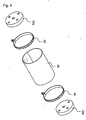
- Fig. 3 is a perspective view of the packing apparatus for pressure type soil-nailing of the present invention
- Fig. 4 is a perspective view with parts taken away of the packing apparatus for pressure type soil-nailing of the present invention
- Fig. 5 is a cross section of the ground for explaining the establishment state of the packing apparatus for pressure type soil-nailing of the present invention.
- the packing apparatus for pressure type soil-nailing of the present invention are inserted the first packing 33a and the second packing 33b at a predetermined interval mutually to a lengthwise direction of the nail 31 in which screw threads are formed on the circumferential surface.
- non-woven fabric 35 that seals empty space between said first packing 33a and second packing 33b by wrapping the circumferential surface of said first packing 33a and second packing 33b.
- non-woven fabric 35 nylon or tent fabric, etc. can be used and it does not matter if any material that has enough resistibility to pressure according to bulk swelling of foaming urethane to be injected into empty space between said first packing 33a and second packing 33b.
- first packing 33a and second packing 33b rubber, soft plastic, wood, steel plate, etc. can be used and rubber of the materials is most desirable.
- the first grouting pipe 37 is established which pierces said first packing 33a and second packing 33b and firstly injects liquid grout in said grouting area
- the discharging pipe 39 of air and foreign material is established which pierces said first packing 33a and second packing 33b and discharges air and foreign material of grouting area due to said grouting.
- one end of said first grouting pipe 37 is established at a longitudinal end of said boring hole, that is, near one end of said nail 31, and it is also desirable that one end of said discharging pipe 39 of air and foreign material is established near said second packing 33b.
- said discharging pipe 39 of air and foreign material does so that pressure can be applied in said grouting area by closing the inlet after discharging air or foreign material as well as discharging to outside of the boring hole foreign materials such as air or water which occurs in said grouting area.
- the packing apparatus for pressure type soil-nailing of the present invention is established so that foaming urethane injection pipe 43 for injecting a quick forming expansion agent such as foaming urethane at space which is sealed by said non-woven fabric 35 may pierce said first packing 33a.
- One end of said foaming urethane injection pipe 43 is situated at space between said first packing 33a and second packing 33b.
- Said foaming urethane becomes gel by injecting liquid urethane in the state in which nail 31 is established and said liquid urethane becomes gel at space between said first packing 33a and second packing 33b, thereby the bulk swells.
- liquid urethane has an advantage that can regulate very variously all sorts of material properties such as foaming magnification and mechanical strength, etc. Because the time in which liquid urethane becomes gel is actually no more than a few minutes, in case of filling this to space which is sealed by non-woven fabric 35, the first liquid grout can be injected in a little while.
- wire rings 45 are established on outside of said non-woven fabric 35 along the circumferential surface of said first and second packing 33a, 33b.
- the packing apparatus for pressure type soil-nailing of the present invention further comprises a second grouting pipe 41.
- Said second grouting pipe 41 pierces said first packing 33a and second packing 33b but is established so that the one end thereof may approximate to said second packing 33b.
- Such second grouting pipe 41 is a pipe for injecting the second liquid grout in order to fill empty space that occurs at interior of boring hole by dry shrinkage of cement after the first grouting.
- Said second grouting pipe 41 fills liquid grouts secondly by a pressure method to space in which the first liquid grout does not to fill, whereby close filling can be done over a whole grouting area, and at the same time it does so that liquid grout can be filled sufficiently to even void that is formed on the ground around the boring hole.
- Soil-nailing construction method using the packing apparatus of the present invention comprises step to dig the ground (S101), step to form the boring hole (S102), step to establish the packing apparatus for pressure type soil-nailing (S103), step to form isolated grouting area (S104), step to fill liquid grout (S105), step to discharge air and foreign material (S106), step to seal grouting area (S107) and step to fill pressurizingly liquid grout (S108).
- step (S101) is executed to dig the ground to a stable height in which slope or wall of pit digging is capable of self-support.
- step (S102) is executed to form the boring hole by boring a hole of a predetermined diameter in a proper position of said dug ground.
- step (S103) is executed to establish by inserting the packing apparatus for pressure type soil-nailing in which the nail 31 such as showed in Fig. 3 is established at the bored hole of said dug ground.
- step (S104) is executed to form isolated grouting area by closely contacting said packing apparatus for pressure type soil-nailing at diameter of the boring hole.
- liquid urethane becomes gel very fast, if passing several minutes after injecting, it becomes gel, whereby the bulk swells.
- isolated grouting area that can inject liquid grout is formed at interior of said boring hole.
- step (S105) is executed to fill by injecting in grouting area liquid grout such as cement milk.
- step (S106) is executed to discharges air or foreign material etc. to outside through the discharging pipe 39 of air and foreign material, at the same time liquid grout is filled in grouting area.
- step (S107) to seal grouting area by blocking a discharge passage of air and foreign material is executed.
- step (S108) to fill pressurizingly liquid grout in said grouting area by continuing to inject liquid grout is executed.
- liquid grout is filled to even void and joint that is formed in the ground surrounding the boring hole.
- step to inject again liquid grout can be further included.
- said second grouting pipe 41 is established so that one end thereof may approximate to said second packing 33b, it can fill liquid grout more easily at surrounding said second packing 33b where due to dry contraction, the first liquid grout was not filled.
- step to establish a wire mesh at wall of the ground is executed.
- step is executed to fix pressurizingly said reinforcing bar with a plate and a nut that are fastened to said nail 31.
- step to place shot-crete is executed, soil-nailing construction method using the packing apparatus for pressure type soil-nailing of the present invention is completed.
- the packing apparatus for pressure type soil-nailing and soil-nailing construction method using the packing apparatus of the present invention has the following effects.
- grouting work can be done in a short time, thereby can shorten a construction time.
- liquid grouting can be filled firmly to even void and joint that is formed at the ground through pressure type soil-nailing, stability of the ground reinforcements can be improved.
Landscapes
- Engineering & Computer Science (AREA)
- Structural Engineering (AREA)
- Mining & Mineral Resources (AREA)
- Life Sciences & Earth Sciences (AREA)
- General Life Sciences & Earth Sciences (AREA)
- Civil Engineering (AREA)
- Paleontology (AREA)
- General Engineering & Computer Science (AREA)
- Geochemistry & Mineralogy (AREA)
- Geology (AREA)
- Consolidation Of Soil By Introduction Of Solidifying Substances Into Soil (AREA)
- Pit Excavations, Shoring, Fill Or Stabilisation Of Slopes (AREA)
- Bulkheads Adapted To Foundation Construction (AREA)
Claims (6)
- Packer zum Versiegeln einer Verfestigungsfläche, indem er in einem Loch, das auf einer aufgegrabenen Fläche gebohrt ist, eingeführt wird, wobei der Packer zur druckartigen Bodenvernagelung umfasst:einen Nagel (31);eine erste Abdichtung (33a) und eine zweite Abdichtung (33b), die in einem vorbestimmten Abstand zueinander in Längsrichtung des Nagels (31) eingepasst sind;ein Vlies (35) zum Versiegeln von Raum zwischen der ersten Abdichtung (33a) und der zweiten Abdichtung (33b), indem es bereitgestellt wird, um die Umfangsfläche der ersten Abdichtung (33a) und zweiten Abdichtung (33b) zu umwickeln;ein erstes Verfestigungsrohr (37) zum Injizieren von flüssigem Verfestigungsmaterial in die Verfestigungsfläche, wobei das erste Verfestigungsrohr (37) die erste Abdichtung (33a) und zweite Abdichtung (33b) durchstößt, aber ein Ende des Rohrs (37) in einer Position nahe des einen Endes des Nagels (31) eingerichtet ist;ein Auslassrohr (39) für Luft und Fremdmaterial zum Auslassen von Luft und Fremdmaterial einer Verfestigungsfläche durch das Verfestigen, wobei das Auslassrohr (39) für Luft und Fremdmaterial die erste Abdichtung (33a) und zweite Abdichtung (33b) durchstößt, aber ein Ende des Rohrs (39) in einer Position nahe der zweiten Abdichtung (33b) eingerichtet ist; undein Urethanschaum-Injektionsrohr (43) zum Injizieren eines Urethanschaums, dessen Volumen aufgrund seiner Gelkonsistenz in einem Raum expandiert wird, der von dem Vlies (35) versiegelt ist, wobei das Urethanschaum-Injektionsrohr (43) die erste Abdichtung (33a) durchstößt, aber ein Ende des Rohrs (43) im Raum zwischen der ersten Abdichtung (33a) und zweiten Abdichtung (33b) eingerichtet ist.
- Packer gemäß Anspruch 1, welcher ferner ein zweites Verfestigungsrohr (41) umfasst zum Injizieren von flüssigem Verfestigungsmaterial in die Verfestigungsfläche durch Durchstoßen der ersten Abdichtung (33a) und zweiten Abdichtung (33b), aber Einrichten seines Endes an einer Position nahe der zweiten Abdichtung (33b).
- Packer gemäß Anspruch 1, welcher ferner Drahtringe (45) umfasst zum engen Verbinden des Vlies (35) auf der Umfangsfläche der ersten und zweiten Abdichtung (33a, 33b) durch Schrauben, wobei die Drahtringe (45) an der Außenseite des Vlies (35) entlang der Umfangsfläche der ersten und zweiten Abdichtung (33a, 33b) eingerichtet sind, um die erste, zweite Abdichtung (33a, 33b) und das Vlies (35) zu verbinden.
- Packer gemäß Anspruch 1, wobei die erste und zweite Abdichtung (33a, 33b) ein Gummimaterial sind.
- Bodenvernagelungskonstruktionsverfahren unter Verwendung eines Packers gemäß Anspruch 1 zur druckartigen Bodenvernagelung, wobei das Verfahren umfasst,
Aufgraben des Bodens bis zu einer stabilen Höhe, bei der ein Hang oder eine Wand einer Grubengrabung sich selbst stützen kann;
Bilden eines Bohrlochs durch Bohren eines Lochs eines vorbestimmten Durchmessers bei einer passenden Position des aufgegrabenen Bodens;
Einrichten durch Einführen in das Bohrloch des Packers zur druckartigen Bodenvernagelung, mit dem ein Nagel (31) eingerichtet wird;
Bilden einer isolierten Verfestigungsfläche zum Injizieren von flüssigem Verfestigungsmaterial durch nahes Inkontaktbringen des Packers zur druckartigen Bodenvernagelung an einem Innendurchmesser des Bohrlochs;
Einfüllen durch Injizieren von flüssigem Verfestigungsmaterial in die Verfestigungsfläche;
Auslassen nach außen von Luft und Fremdmaterial in der Verfestigungsfläche, wenn flüssiges Verfestigungsmaterial in die Verfestigungsfläche injiziert wird;
Versiegeln der Verfestigungsfläche durch Blockieren eines Durchgangs, in den die Luft und Fremdmaterial ausgelassen werden; und
Einfüllen von flüssigem Verfestigungsmaterial unter Druck in die Verfestigungsfläche, so dass flüssiges Verfestigungsmaterial sogar Leerraum und Spalten des Bodens auffüllen kann, der das Bohrloch umgibt. - Bodenvernagelungskonstruktionsverfahren gemäß Anspruch 5, welches ferner umfasst
Nochmaliges Eingießen von flüssigem Verfestigungsmaterial, nachdem eine vorbestimmte Zeit seit Abschluss des Schritts des Einfüllens von flüssigem Verfestigungsmaterial unter Druck in die Verfestigungsfläche vorübergegangen ist.
Applications Claiming Priority (2)
| Application Number | Priority Date | Filing Date | Title |
|---|---|---|---|
| KR2002018948 | 2002-06-22 | ||
| KR2020020018948U KR200290351Y1 (ko) | 2002-06-22 | 2002-06-22 | 압력식 쏘일네일링용 패커기 |
Publications (3)
| Publication Number | Publication Date |
|---|---|
| EP1375754A2 EP1375754A2 (de) | 2004-01-02 |
| EP1375754A3 EP1375754A3 (de) | 2004-09-15 |
| EP1375754B1 true EP1375754B1 (de) | 2009-04-29 |
Family
ID=31185701
Family Applications (1)
| Application Number | Title | Priority Date | Filing Date |
|---|---|---|---|
| EP02024268A Expired - Fee Related EP1375754B1 (de) | 2002-06-22 | 2002-10-31 | Packer und Verfahren zur Bodenvernagelung |
Country Status (5)
| Country | Link |
|---|---|
| US (1) | US20030235472A1 (de) |
| EP (1) | EP1375754B1 (de) |
| JP (1) | JP2004027813A (de) |
| KR (1) | KR200290351Y1 (de) |
| DE (1) | DE60232139D1 (de) |
Families Citing this family (34)
| Publication number | Priority date | Publication date | Assignee | Title |
|---|---|---|---|---|
| US7338233B2 (en) | 2003-12-18 | 2008-03-04 | Barrett Robert K | Soil nail and method of installing a subsurface support |
| US8851801B2 (en) | 2003-12-18 | 2014-10-07 | R&B Leasing, Llc | Self-centralizing soil nail and method of creating subsurface support |
| US9273442B2 (en) | 2003-12-18 | 2016-03-01 | R&B Leasing, Llc | Composite self-drilling soil nail and method |
| CN100340723C (zh) * | 2005-05-23 | 2007-10-03 | 邓敬森 | 边坡加固方法 |
| KR100795204B1 (ko) | 2006-05-30 | 2008-01-16 | 김상수 | 지수기능을 겸비한 가압 그라우팅용 패커 |
| KR100795202B1 (ko) | 2006-05-30 | 2008-01-16 | 김상수 | 지수기능을 겸비한 가압 그라우팅용 패커 |
| US7384217B1 (en) | 2007-03-29 | 2008-06-10 | Barrett Robert K | System and method for soil stabilization of sloping surface |
| KR100773920B1 (ko) | 2007-05-03 | 2007-11-07 | 주식회사 도담이앤씨 | 정착부 확공 및 고강도 강봉을 이용한 프리-텐션 쏘일네일링 시스템 및 이를 이용한 사면 안정보강 공법 |
| KR101018867B1 (ko) * | 2008-05-06 | 2011-03-04 | 이재일 | 가압 그라우팅을 위한 재사용 패커 |
| KR100934196B1 (ko) * | 2009-03-06 | 2009-12-24 | 주식회사 도담이앤씨 | 양방향 압력식 소구경 파일 및 이를 이용한 부력방지 공법 |
| KR100925677B1 (ko) | 2009-06-30 | 2009-11-10 | 그린이엔지 주식회사 | 복합 사면 안정 공법 |
| CN102041812B (zh) * | 2009-10-22 | 2012-03-07 | 宁晋生 | 一种三角形布置钢筋的注浆土钉 |
| KR101143609B1 (ko) * | 2010-01-26 | 2012-05-09 | 주식회사 프라임씨스템 | 깔때기형 패커와 이를 이용한 압력식 쏘일 네일링 공법 |
| US8376661B2 (en) | 2010-05-21 | 2013-02-19 | R&B Leasing, Llc | System and method for increasing roadway width incorporating a reverse oriented retaining wall and soil nail supports |
| KR101032745B1 (ko) | 2010-09-16 | 2011-05-06 | 배진령 | 코킹모듈 및 이를 구비한 그라우팅 장치, 이를 이용한 터널 보강공법 |
| CN102140901B (zh) * | 2011-05-13 | 2013-11-20 | 中国矿业大学 | 一种耐高压钻孔密封方法 |
| CN102296603B (zh) * | 2011-06-02 | 2013-06-05 | 北京科技大学 | 一种锚杆(锚索)用止浆塞及止浆系统 |
| CN102287163B (zh) * | 2011-09-08 | 2013-09-11 | 重庆市能源投资集团科技有限责任公司 | 煤矿井下超高压压裂孔的钻孔封孔方法及封孔装置 |
| CN102747980A (zh) * | 2012-07-18 | 2012-10-24 | 中国矿业大学 | 膨胀式多级带压快速封孔技术 |
| KR101260292B1 (ko) * | 2012-08-28 | 2013-05-15 | 양재이엔지 주식회사 | 그라우팅장치를 이용한 터널 보강공법 |
| KR101394985B1 (ko) * | 2012-08-28 | 2014-05-19 | 양재이엔지 주식회사 | 터널 그라우팅 장치를 이용한 터널 보강공법 |
| CN103498687B (zh) * | 2013-09-04 | 2015-10-21 | 中国矿业大学 | 一种注浆锚杆的封孔装置及方法 |
| CN103742115B (zh) * | 2013-12-18 | 2016-03-23 | 中国矿业大学 | 一种煤矿井下压裂密封装置及方法 |
| CN104481450A (zh) * | 2014-11-07 | 2015-04-01 | 北京中煤矿山工程有限公司 | 水文孔封孔方法 |
| KR101771670B1 (ko) * | 2015-07-10 | 2017-08-29 | 주식회사 장평건설 | 지중 삽입용 그라우팅 장치 및 공법 |
| CN105239586B (zh) * | 2015-11-05 | 2017-04-12 | 云南省建设投资控股集团有限公司 | 一种采用支撑结构支护基坑的方法 |
| CN105696599B (zh) * | 2016-02-06 | 2018-06-12 | 北京市勘察设计研究院有限公司 | 一种通过利用气囊封堵装置的加压注浆方法 |
| KR20170125457A (ko) * | 2016-05-04 | 2017-11-15 | 공학봉 | 전단저항력 향상기능을 갖는 압력식 쏘일 네일링 공법 및 이를 이용한 절토부 패널식 옹벽 |
| CN106401524A (zh) * | 2016-12-07 | 2017-02-15 | 平安煤炭开采工程技术研究院有限责任公司 | 注浆装置和压裂封孔装置 |
| JP6905863B2 (ja) * | 2017-05-18 | 2021-07-21 | 株式会社ケー・エフ・シー | 調整部材及びこれを用いた構造物の施工方法 |
| CN111502641A (zh) * | 2020-04-27 | 2020-08-07 | 淮南矿业(集团)有限责任公司 | 瓦斯测压装置及瓦斯测压方法 |
| CN112921985A (zh) * | 2021-02-02 | 2021-06-08 | 河南省远基岩土工程有限公司 | 一种相邻基坑开挖支护体和支护方法 |
| CN114182738A (zh) * | 2021-12-29 | 2022-03-15 | 中铁十二局集团建筑安装工程有限公司 | 一种受限空间基坑开挖支护施工方法 |
| CN116971399A (zh) * | 2023-09-22 | 2023-10-31 | 中交第一航务工程局有限公司 | 桥梁主墩承台基坑支护结构及其施工方法 |
Family Cites Families (5)
| Publication number | Priority date | Publication date | Assignee | Title |
|---|---|---|---|---|
| GB1564348A (en) * | 1977-10-03 | 1980-04-10 | Dividag Stressed Concrete Ltd | Packer for use with earth or rock anchors |
| CH671790A5 (de) * | 1986-08-13 | 1989-09-29 | Vsl Int Ag | |
| JP3348749B2 (ja) * | 1994-06-30 | 2002-11-20 | 日本基礎技術株式会社 | ケーシング管の回収方法 |
| JPH11200365A (ja) * | 1998-01-07 | 1999-07-27 | Hokuriku Engineering Kk | アンカー用定着装置及びその定着方法 |
| US6135204A (en) * | 1998-10-07 | 2000-10-24 | Mccabe; Howard Wendell | Method for placing instrumentation in a bore hole |
-
2002
- 2002-06-22 KR KR2020020018948U patent/KR200290351Y1/ko not_active IP Right Cessation
- 2002-10-31 EP EP02024268A patent/EP1375754B1/de not_active Expired - Fee Related
- 2002-10-31 JP JP2002317469A patent/JP2004027813A/ja active Pending
- 2002-10-31 US US10/284,967 patent/US20030235472A1/en not_active Abandoned
- 2002-10-31 DE DE60232139T patent/DE60232139D1/de not_active Expired - Fee Related
Also Published As
| Publication number | Publication date |
|---|---|
| EP1375754A2 (de) | 2004-01-02 |
| EP1375754A3 (de) | 2004-09-15 |
| DE60232139D1 (de) | 2009-06-10 |
| JP2004027813A (ja) | 2004-01-29 |
| KR200290351Y1 (ko) | 2002-09-27 |
| US20030235472A1 (en) | 2003-12-25 |
Similar Documents
| Publication | Publication Date | Title |
|---|---|---|
| EP1375754B1 (de) | Packer und Verfahren zur Bodenvernagelung | |
| JP2004027813A5 (de) | ||
| KR100978006B1 (ko) | 더블밀폐 압력식 쏘일 네일링 공법 | |
| KR100859872B1 (ko) | 굴곡형 정착 패커를 갖는 앵커체 시공방법 | |
| KR100766450B1 (ko) | 정착지지체로 이루어진 지반정착앵커구조체 및 이를 이용한연약지반내 앵커시공방법 | |
| JP2008248524A (ja) | 鋼管杭の施工方法 | |
| KR200344961Y1 (ko) | 강관 동시 그라우팅 구조 | |
| KR101141526B1 (ko) | 압력 그라우팅공법 | |
| KR101029320B1 (ko) | 암반 파쇄대구간 보강을 위한 록볼트 및 이를 이용한 암반파쇄대구간 보강방법 | |
| GB2264739A (en) | Diaphragm wall with liquid tight joints | |
| KR101586437B1 (ko) | 그라우팅 충진부를 구비하는 사방댐의 그라우팅 공법 | |
| KR100455915B1 (ko) | 마이크로파일용 패커 및 이를 이용한 압력식 마이크로파일 시공방법 | |
| KR100991248B1 (ko) | 팩을 이용한 마이크로 파일 기초공법 및 이에 사용되는파일 조립체 | |
| JP4219747B2 (ja) | 土木用袋体 | |
| JP3481508B2 (ja) | 石積擁壁補強方法 | |
| KR20140062914A (ko) | 지중 앵커파일의 구근확장방법 및 상기 방법에 사용되는 구근확장장치 | |
| KR200381572Y1 (ko) | 밀크그라우팅을 이용하여 가압을 할 수 있는 패커 | |
| KR101816006B1 (ko) | 매입말뚝 주면고정방법 및 그 장치 | |
| KR20090130515A (ko) | 지반정착 앵커시스템 및 이를 이용한 연약지반 앵커구조체시공방법 | |
| KR100710866B1 (ko) | 밀크그라우팅을 이용한 가압 그라우팅 공법 및 패커 | |
| KR102070912B1 (ko) | 흙막이 벽체용 phc 파일, 이를 제조하기 위한 몰드 조립체 및 이를 이용한 제조방법 | |
| KR100869369B1 (ko) | 다발강관을 이용한 그라우팅 방식의 지반보강장치 및 이를통한 지반보강공법 | |
| JP3790232B2 (ja) | パッカーおよびそれを用いた地山補強工法 | |
| KR200337877Y1 (ko) | 지반 보강을 위한 압력식 그라우팅 장치 | |
| JP2007170115A (ja) | 抑止機能付集排水パイプ |
Legal Events
| Date | Code | Title | Description |
|---|---|---|---|
| PUAI | Public reference made under article 153(3) epc to a published international application that has entered the european phase |
Free format text: ORIGINAL CODE: 0009012 |
|
| AK | Designated contracting states |
Kind code of ref document: A2 Designated state(s): AT BE BG CH CY CZ DE DK EE ES FI FR GB GR IE IT LI LU MC NL PT SE SK TR |
|
| AX | Request for extension of the european patent |
Extension state: AL LT LV MK RO SI |
|
| PUAL | Search report despatched |
Free format text: ORIGINAL CODE: 0009013 |
|
| AK | Designated contracting states |
Kind code of ref document: A3 Designated state(s): AT BE BG CH CY CZ DE DK EE ES FI FR GB GR IE IT LI LU MC NL PT SE SK TR |
|
| AX | Request for extension of the european patent |
Extension state: AL LT LV MK RO SI |
|
| RIC1 | Information provided on ipc code assigned before grant |
Ipc: 7E 02D 5/76 A Ipc: 7E 02D 5/80 B |
|
| 17P | Request for examination filed |
Effective date: 20050304 |
|
| AKX | Designation fees paid |
Designated state(s): DE FR GB |
|
| 17Q | First examination report despatched |
Effective date: 20061121 |
|
| GRAP | Despatch of communication of intention to grant a patent |
Free format text: ORIGINAL CODE: EPIDOSNIGR1 |
|
| GRAS | Grant fee paid |
Free format text: ORIGINAL CODE: EPIDOSNIGR3 |
|
| GRAA | (expected) grant |
Free format text: ORIGINAL CODE: 0009210 |
|
| AK | Designated contracting states |
Kind code of ref document: B1 Designated state(s): DE FR GB |
|
| REG | Reference to a national code |
Ref country code: GB Ref legal event code: FG4D |
|
| REF | Corresponds to: |
Ref document number: 60232139 Country of ref document: DE Date of ref document: 20090610 Kind code of ref document: P |
|
| PLBE | No opposition filed within time limit |
Free format text: ORIGINAL CODE: 0009261 |
|
| STAA | Information on the status of an ep patent application or granted ep patent |
Free format text: STATUS: NO OPPOSITION FILED WITHIN TIME LIMIT |
|
| 26N | No opposition filed |
Effective date: 20100201 |
|
| PG25 | Lapsed in a contracting state [announced via postgrant information from national office to epo] |
Ref country code: DE Free format text: LAPSE BECAUSE OF NON-PAYMENT OF DUE FEES Effective date: 20100501 |
|
| PG25 | Lapsed in a contracting state [announced via postgrant information from national office to epo] |
Ref country code: GB Free format text: LAPSE BECAUSE OF NON-PAYMENT OF DUE FEES Effective date: 20091031 |
|
| PGFP | Annual fee paid to national office [announced via postgrant information from national office to epo] |
Ref country code: FR Payment date: 20111110 Year of fee payment: 10 |
|
| REG | Reference to a national code |
Ref country code: FR Ref legal event code: ST Effective date: 20130628 |
|
| PG25 | Lapsed in a contracting state [announced via postgrant information from national office to epo] |
Ref country code: FR Free format text: LAPSE BECAUSE OF NON-PAYMENT OF DUE FEES Effective date: 20121031 |