EP1372842B1 - A reactor for plasma assisted treatment of gaseous - Google Patents
A reactor for plasma assisted treatment of gaseous Download PDFInfo
- Publication number
- EP1372842B1 EP1372842B1 EP02718282.3A EP02718282A EP1372842B1 EP 1372842 B1 EP1372842 B1 EP 1372842B1 EP 02718282 A EP02718282 A EP 02718282A EP 1372842 B1 EP1372842 B1 EP 1372842B1
- Authority
- EP
- European Patent Office
- Prior art keywords
- reactor
- gaseous medium
- layer
- gas flow
- electrodes
- Prior art date
- Legal status (The legal status is an assumption and is not a legal conclusion. Google has not performed a legal analysis and makes no representation as to the accuracy of the status listed.)
- Expired - Lifetime
Links
Images
Classifications
-
- F—MECHANICAL ENGINEERING; LIGHTING; HEATING; WEAPONS; BLASTING
- F01—MACHINES OR ENGINES IN GENERAL; ENGINE PLANTS IN GENERAL; STEAM ENGINES
- F01N—GAS-FLOW SILENCERS OR EXHAUST APPARATUS FOR MACHINES OR ENGINES IN GENERAL; GAS-FLOW SILENCERS OR EXHAUST APPARATUS FOR INTERNAL-COMBUSTION ENGINES
- F01N3/00—Exhaust or silencing apparatus having means for purifying, rendering innocuous, or otherwise treating exhaust
- F01N3/08—Exhaust or silencing apparatus having means for purifying, rendering innocuous, or otherwise treating exhaust for rendering innocuous
- F01N3/0892—Electric or magnetic treatment, e.g. dissociation of noxious components
-
- B—PERFORMING OPERATIONS; TRANSPORTING
- B01—PHYSICAL OR CHEMICAL PROCESSES OR APPARATUS IN GENERAL
- B01D—SEPARATION
- B01D53/00—Separation of gases or vapours; Recovering vapours of volatile solvents from gases; Chemical or biological purification of waste gases, e.g. engine exhaust gases, smoke, fumes, flue gases, aerosols
- B01D53/34—Chemical or biological purification of waste gases
- B01D53/92—Chemical or biological purification of waste gases of engine exhaust gases
- B01D53/922—Mixtures of carbon monoxide or hydrocarbons and nitrogen oxides
-
- B—PERFORMING OPERATIONS; TRANSPORTING
- B01—PHYSICAL OR CHEMICAL PROCESSES OR APPARATUS IN GENERAL
- B01J—CHEMICAL OR PHYSICAL PROCESSES, e.g. CATALYSIS OR COLLOID CHEMISTRY; THEIR RELEVANT APPARATUS
- B01J12/00—Chemical processes in general for reacting gaseous media with gaseous media; Apparatus specially adapted therefor
- B01J12/002—Chemical processes in general for reacting gaseous media with gaseous media; Apparatus specially adapted therefor carried out in the plasma state
-
- B—PERFORMING OPERATIONS; TRANSPORTING
- B01—PHYSICAL OR CHEMICAL PROCESSES OR APPARATUS IN GENERAL
- B01J—CHEMICAL OR PHYSICAL PROCESSES, e.g. CATALYSIS OR COLLOID CHEMISTRY; THEIR RELEVANT APPARATUS
- B01J12/00—Chemical processes in general for reacting gaseous media with gaseous media; Apparatus specially adapted therefor
- B01J12/007—Chemical processes in general for reacting gaseous media with gaseous media; Apparatus specially adapted therefor in the presence of catalytically active bodies, e.g. porous plates
-
- B—PERFORMING OPERATIONS; TRANSPORTING
- B01—PHYSICAL OR CHEMICAL PROCESSES OR APPARATUS IN GENERAL
- B01J—CHEMICAL OR PHYSICAL PROCESSES, e.g. CATALYSIS OR COLLOID CHEMISTRY; THEIR RELEVANT APPARATUS
- B01J19/00—Chemical, physical or physico-chemical processes in general; Their relevant apparatus
- B01J19/08—Processes employing the direct application of electric or wave energy, or particle radiation; Apparatus therefor
- B01J19/087—Processes employing the direct application of electric or wave energy, or particle radiation; Apparatus therefor employing electric or magnetic energy
- B01J19/088—Processes employing the direct application of electric or wave energy, or particle radiation; Apparatus therefor employing electric or magnetic energy giving rise to electric discharges
-
- B—PERFORMING OPERATIONS; TRANSPORTING
- B01—PHYSICAL OR CHEMICAL PROCESSES OR APPARATUS IN GENERAL
- B01J—CHEMICAL OR PHYSICAL PROCESSES, e.g. CATALYSIS OR COLLOID CHEMISTRY; THEIR RELEVANT APPARATUS
- B01J19/00—Chemical, physical or physico-chemical processes in general; Their relevant apparatus
- B01J19/24—Stationary reactors without moving elements inside
- B01J19/2475—Membrane reactors
-
- C—CHEMISTRY; METALLURGY
- C01—INORGANIC CHEMISTRY
- C01B—NON-METALLIC ELEMENTS; COMPOUNDS THEREOF; METALLOIDS OR COMPOUNDS THEREOF NOT COVERED BY SUBCLASS C01C
- C01B3/00—Hydrogen; Gaseous mixtures containing hydrogen; Separation of hydrogen from mixtures containing it; Purification of hydrogen
- C01B3/02—Production of hydrogen or of gaseous mixtures containing a substantial proportion of hydrogen
- C01B3/32—Production of hydrogen or of gaseous mixtures containing a substantial proportion of hydrogen by reaction of gaseous or liquid organic compounds with gasifying agents, e.g. water, carbon dioxide, air
- C01B3/34—Production of hydrogen or of gaseous mixtures containing a substantial proportion of hydrogen by reaction of gaseous or liquid organic compounds with gasifying agents, e.g. water, carbon dioxide, air by reaction of hydrocarbons with gasifying agents
- C01B3/342—Production of hydrogen or of gaseous mixtures containing a substantial proportion of hydrogen by reaction of gaseous or liquid organic compounds with gasifying agents, e.g. water, carbon dioxide, air by reaction of hydrocarbons with gasifying agents with the aid of electrical means, electromagnetic or mechanical vibrations, or particle radiations
-
- B—PERFORMING OPERATIONS; TRANSPORTING
- B01—PHYSICAL OR CHEMICAL PROCESSES OR APPARATUS IN GENERAL
- B01D—SEPARATION
- B01D2259/00—Type of treatment
- B01D2259/80—Employing electric, magnetic, electromagnetic or wave energy, or particle radiation
- B01D2259/818—Employing electrical discharges or the generation of a plasma
-
- B—PERFORMING OPERATIONS; TRANSPORTING
- B01—PHYSICAL OR CHEMICAL PROCESSES OR APPARATUS IN GENERAL
- B01J—CHEMICAL OR PHYSICAL PROCESSES, e.g. CATALYSIS OR COLLOID CHEMISTRY; THEIR RELEVANT APPARATUS
- B01J2219/00—Chemical, physical or physico-chemical processes in general; Their relevant apparatus
- B01J2219/08—Processes employing the direct application of electric or wave energy, or particle radiation; Apparatus therefor
- B01J2219/0803—Processes employing the direct application of electric or wave energy, or particle radiation; Apparatus therefor employing electric or magnetic energy
- B01J2219/0805—Processes employing the direct application of electric or wave energy, or particle radiation; Apparatus therefor employing electric or magnetic energy giving rise to electric discharges
- B01J2219/0807—Processes employing the direct application of electric or wave energy, or particle radiation; Apparatus therefor employing electric or magnetic energy giving rise to electric discharges involving electrodes
- B01J2219/0809—Processes employing the direct application of electric or wave energy, or particle radiation; Apparatus therefor employing electric or magnetic energy giving rise to electric discharges involving electrodes employing two or more electrodes
- B01J2219/0813—Processes employing the direct application of electric or wave energy, or particle radiation; Apparatus therefor employing electric or magnetic energy giving rise to electric discharges involving electrodes employing two or more electrodes employing four electrodes
-
- B—PERFORMING OPERATIONS; TRANSPORTING
- B01—PHYSICAL OR CHEMICAL PROCESSES OR APPARATUS IN GENERAL
- B01J—CHEMICAL OR PHYSICAL PROCESSES, e.g. CATALYSIS OR COLLOID CHEMISTRY; THEIR RELEVANT APPARATUS
- B01J2219/00—Chemical, physical or physico-chemical processes in general; Their relevant apparatus
- B01J2219/08—Processes employing the direct application of electric or wave energy, or particle radiation; Apparatus therefor
- B01J2219/0803—Processes employing the direct application of electric or wave energy, or particle radiation; Apparatus therefor employing electric or magnetic energy
- B01J2219/0805—Processes employing the direct application of electric or wave energy, or particle radiation; Apparatus therefor employing electric or magnetic energy giving rise to electric discharges
- B01J2219/0807—Processes employing the direct application of electric or wave energy, or particle radiation; Apparatus therefor employing electric or magnetic energy giving rise to electric discharges involving electrodes
- B01J2219/0824—Details relating to the shape of the electrodes
- B01J2219/0835—Details relating to the shape of the electrodes substantially flat
-
- B—PERFORMING OPERATIONS; TRANSPORTING
- B01—PHYSICAL OR CHEMICAL PROCESSES OR APPARATUS IN GENERAL
- B01J—CHEMICAL OR PHYSICAL PROCESSES, e.g. CATALYSIS OR COLLOID CHEMISTRY; THEIR RELEVANT APPARATUS
- B01J2219/00—Chemical, physical or physico-chemical processes in general; Their relevant apparatus
- B01J2219/08—Processes employing the direct application of electric or wave energy, or particle radiation; Apparatus therefor
- B01J2219/0873—Materials to be treated
- B01J2219/0881—Two or more materials
- B01J2219/0883—Gas-gas
-
- B—PERFORMING OPERATIONS; TRANSPORTING
- B01—PHYSICAL OR CHEMICAL PROCESSES OR APPARATUS IN GENERAL
- B01J—CHEMICAL OR PHYSICAL PROCESSES, e.g. CATALYSIS OR COLLOID CHEMISTRY; THEIR RELEVANT APPARATUS
- B01J2219/00—Chemical, physical or physico-chemical processes in general; Their relevant apparatus
- B01J2219/08—Processes employing the direct application of electric or wave energy, or particle radiation; Apparatus therefor
- B01J2219/0873—Materials to be treated
- B01J2219/0892—Materials to be treated involving catalytically active material
-
- B—PERFORMING OPERATIONS; TRANSPORTING
- B01—PHYSICAL OR CHEMICAL PROCESSES OR APPARATUS IN GENERAL
- B01J—CHEMICAL OR PHYSICAL PROCESSES, e.g. CATALYSIS OR COLLOID CHEMISTRY; THEIR RELEVANT APPARATUS
- B01J2219/00—Chemical, physical or physico-chemical processes in general; Their relevant apparatus
- B01J2219/08—Processes employing the direct application of electric or wave energy, or particle radiation; Apparatus therefor
- B01J2219/0894—Processes carried out in the presence of a plasma
- B01J2219/0896—Cold plasma
-
- C—CHEMISTRY; METALLURGY
- C01—INORGANIC CHEMISTRY
- C01B—NON-METALLIC ELEMENTS; COMPOUNDS THEREOF; METALLOIDS OR COMPOUNDS THEREOF NOT COVERED BY SUBCLASS C01C
- C01B2203/00—Integrated processes for the production of hydrogen or synthesis gas
- C01B2203/04—Integrated processes for the production of hydrogen or synthesis gas containing a purification step for the hydrogen or the synthesis gas
- C01B2203/0405—Purification by membrane separation
- C01B2203/041—In-situ membrane purification during hydrogen production
-
- F—MECHANICAL ENGINEERING; LIGHTING; HEATING; WEAPONS; BLASTING
- F01—MACHINES OR ENGINES IN GENERAL; ENGINE PLANTS IN GENERAL; STEAM ENGINES
- F01N—GAS-FLOW SILENCERS OR EXHAUST APPARATUS FOR MACHINES OR ENGINES IN GENERAL; GAS-FLOW SILENCERS OR EXHAUST APPARATUS FOR INTERNAL-COMBUSTION ENGINES
- F01N2240/00—Combination or association of two or more different exhaust treating devices, or of at least one such device with an auxiliary device, not covered by indexing codes F01N2230/00 or F01N2250/00, one of the devices being
- F01N2240/28—Combination or association of two or more different exhaust treating devices, or of at least one such device with an auxiliary device, not covered by indexing codes F01N2230/00 or F01N2250/00, one of the devices being a plasma reactor
Definitions
- the invention relates to the plasma assisted treatment of gaseous media and more particularly to the treatment of gaseous media in which particulate material is entrained.
- the invention has particular application for the plasma-assisted processing of gaseous media for the reduction of the emissions of one or more of nitrogenous oxides, particulate including carbonaceous particulate, hydrocarbons including polyaromatic hydrocarbons and soluble organic fractions, carbon monoxide and other regulated or unregulated combustion products from the exhausts of internal combustion engines.
- the particulate matter is removed from diesel exhaust gases by a simple, physical trapping of particulate matter in the interstices of a porous, usually ceramic, filter body, which is then regenerated by heating the filter body to a temperature at which the trapped diesel exhaust particulates are burnt off.
- the filter body is monolithic, although EP 0 010 384 does mention the use of ceramic beads, wire meshes or metal screens as well.
- US patent 4,427,418 discloses the use of ceramic coated wire or ceramic fibres.
- precipitation In a broader context, the precipitation of charged particulate matter by electrostatic forces also is known. However, in this case, precipitation usually takes place upon large planar electrodes or metal screens.
- GB patent 2,274,412 discloses a method and apparatus for removing particulate and other pollutants from internal combustion engine exhaust gases, in which the exhaust gases are passed through a bed of charged pellets of material, preferably ferroelectric, having high dielectric constant.
- pellets of material preferably ferroelectric, having high dielectric constant.
- Plasma assisted gas processing reactors have also been proposed which operate in the so-called "silent discharge” mode.
- Such silent discharges are produced in a gas between electrodes, between which there is at least one dielectric layer or dielectric material arranged so that there is no possibility for a direct, that is metal-to-metal, discharge through the gas.
- Such silent discharge reactors are also referred to as dielectric barrier reactors.
- a silent discharge reactor of this type is disclosed in US 5,746,051 , the reactor comprising a number of flat rectangular electrodes, as well as the same number less one of flat rectangular insulating plates interleaved between the electrodes in parallel therewith.
- US 5,746,051 also identifies a number of prior art devices known for producing silent discharges.
- WO 00/71866 discloses an apparatus for removing particulate and other pollutants from internal combustion engine exhaust gases.
- the apparatus is also a dielectric barrier reactor for the plasma-assisted processing of a gaseous medium in which the gaseous medium is constrained to pass between the co-axial electrodes with axial, radial and circumferential gas flow component combinations which result in the gas flow being at least partially helical and/or spiral.
- Such dielectric barrier reactors or other non-thermal plasma reactors including the reactors described herein can be used for applications other than vehicle applications for the treatment of combustion products from the exhausts of internal combustion engines.
- These other applications include reforming of hydrocarbon-based liquid or gaseous fuels or fuel processing to produce hydrogen containing streams and/or streams containing oxygenated fuels that can be used for applications including fuel cell applications in vehicles or stationary fuel cell applications, and for liquid fuel production by reforming gases such as methane.
- Reactors of the silent discharge type (such as disclosed in US 5,746,051 ) having an array of alternate polarity parallel plate electrodes with intervening dielectric barriers are advantageous in providing efficient plasma generation in the spaces between plates/barriers.
- a problem with this type of reactor is that, where the gas contains particulate matter, such as soot, the residence time of the gas in a reactor of practical proportions is insufficient for plasma assisted oxidation of the particulate matter to be completed. It is therefore necessary to trap the particulate material, which can be done by introducing a packed bed of pellets into the gas flow space, the packed bed acting as a filter on which particulate matter is trapped.
- the electric field is insufficient to enable a plasma to be established in a gaseous medium as it flows through that region. Also deposition tends to be concentrated at the gas inlet region.
- US 4,871,515 discloses an electrostatic particle filter device which comprises a collecting electrode which can trap particles present in a gas passing through the device. The particles are then oxidised by a corona discharge.
- the reactor is as defined in claim 1.
- a reactor of the silent discharge or dielectric barrier type for plasma assisted treatment of a gaseous medium which reactor comprises at least one pair of electrodes between which is an intervening dielectric barrier layer defining between at least one of the electrodes and the dielectric barrier layer at least one gas flow path through which gaseous medium may pass, such that, in use, a plasma discharge is generated in the gaseous medium by application of an appropriate electrical potential across the or each electrode pair, a layer of material between the electrodes, which layer may comprise the said dielectric barrier layer or may be separate therefrom, and which provides a surface over which the gaseous medium flows, the surface extending along at least part of the length of the said gas flow path, and means for causing entrapment on the said surface of selected species or particulate matter in the gaseous medium.
- the said means for causing entrapment comprises a source of direct, alternating or pulsed voltage applied so as to electrostatically trap on the said surface particulate matter in the gaseous medium.
- a source of direct, alternating or pulsed voltage applied so as to electrostatically trap on the said surface particulate matter in the gaseous medium.
- the said layer of material is provided by permeable filter material in sheet form and the said gas flow path is such that the gaseous medium is directed to flow through the sheet form filter material, whereby selected species or particulate material in the gaseous medium is entrapped on the surface thereof.
- One or both sides of the said layer of material may be provided with a coating.
- the coating may be such as will act as a catalyst for the removal of nitrogenous oxides or for the removal of carbonaceous material.
- the catalyst on one surface may catalyse one reaction (such as reduction of nitrogenous oxides) and the catalyst on the other surface may catalyse a different reaction (such as oxidation of carbonaceous material).
- the coating or coatings may contain a mixture of catalysts.
- an electrical power supply is connected to apply a high voltage alternating or pulsed or direct current electrical potential or combination of these potentials to the electrodes so as to generate a plasma in a gaseous medium between the electrodes and such as to act upon the said surface, thereby to assist in the oxidation of particulate matter entrapped thereon or the promotion of reactions including catalytic reactions involving entrapped selected species.
- Catalytic materials may be present in the plasma region to aid in the removal of nitrogenous oxides and carbonaceous material.
- triangular waves, sine waves, square wave, saw-tooth wave of the same or similar characteristics can be used separately or in combination.
- the electrodes are so arranged as to promote surface discharge to take place along the said surface on which particulate matter or selected species is entrapped.
- Such surface discharge can be arranged to provide substantially uniform plasma treatment of particulate matter or selected species trapped on the surface.
- a bulk or volume plasma discharge can also be present in addition to the surface discharge.
- an array of discrete electrodes is positioned close to the said surface, each discrete electrode being electrically insulated from neighbouring electrodes, whereby application across each successive pair of the said discrete electrodes of a high voltage alternating or pulsed or direct electrical potential to generate plasma in gaseous medium adjacent the said surface causes surface discharge across the said surface between the electrode pairs.
- the electrical power in the plasma is applied to the surface where the particulate material or selected species is trapped so that the surface discharge enhances reactions thereof and/or the catalytic action of the surface for treating the gaseous media.
- a high electric field in the surface region of the filter material extends into the boundary layer region of the gas flow, a region where the gas flow is pseudo-laminar.
- the or each dielectric barrier layer is in intimate contact with an electrode.
- intimate contact we mean that the dielectric layer is either chemically bonded to the, usually metal, electrode or that the dielectric layer is in physical contact with the electrode. This intimate contact reduces any losses due to discharges or corona in any gaps between the electrode and barrier.
- the means that the power applied to the reactor is more efficiently coupled for generating a plasma discharge for processing of the gaseous media. Reducing these losses increases the efficiency of the dielectric barrier reactor and power supply system for a vehicle application and so reduces the power requirement and possible fuel penalty which are key considerations for any design. Reducing such losses also helps minimise electromagnetic emissions improving electromagnetic compatibility for vehicle applications.
- the physical contact between the electrode and dielectric material may be enhanced by depositing a metallised layer as a coating onto the dielectric material.
- the layer can be deposited electrolytically or by screen printing and can be made of, but is not restricted to, a suitable conducting material such as silver, nickel or copper.
- the metallised layer can also constitute the electrode.
- an intermediate layer of molybdenum/manganese can first be deposited on the dielectric material and fired on at around 1400°C causing some of the metal to diffuse into the dielectric material surface.
- a conducting layer, for example nickel is then deposited onto the molybdenum/manganese so that the nickel makes a uniform contact with the diffused metal layer on the dielectric material.
- a strong, intimately bonded, metallised layer on the dielectric material is achieved between the nickel-metal electrode and the dielectric material.
- enhanced formation of discharge streamers into the gas flow path and emanating from dielectric surfaces is achieved by providing on those surfaces exposed to gas an isolated discontinuous metallic film, preferably less than 10 ⁇ m in thickness and not connected to an external source of electric potential.
- the discontinuous metallic film may be in the form of spots or dots of metal and can be present on one or more of the dielectric barriers.
- the metal provides a richer source of electrons than the dielectric material and has the effect of increasing the number of discharge points emanating from one or more of the barriers and thereby increasing the efficiency of treatment of exhaust gasses.
- the gas flow path on the downstream side of the layer of filter material may be packed with a gas permeable bed of an active material.
- the permeable filter material in sheet form may be the active material that may be selected to act as a catalyst with respect to the treatment of the gaseous medium that passes through the reactor.
- the material of the said layer of filter material may be selected to act as a catalyst, or a catalytic material may be coated, or otherwise incorporated, on or in the layer of filter material.
- the material of the layer or coating may be selected to be catalytic to increase the efficiency of oxidation of particulates and/or the reduction of nitrogenous oxides to nitrogen present in the exhaust from internal combustion engines.
- a preferred arrangement is for the layer of filter material to be such as to catalyse the oxidation of particulates trapped thereon and for the gas flow path downstream of the layer of filter material to be packed with material which catalyses the reduction of nitrogenous oxides to nitrogen.
- the layer of filter material may also be catalytic for the reduction of nitrogen oxides.
- components of the reactor such as the dielectric barrier layer material can be coated, partially or fully with a material or materials or combination of materials to act as a catalyst for removal of nitrogenous oxides and carbonaceous material.
- a packing material, layer material or coating that is not catalytic for the oxidation of carbonaceous particulate or reduction of nitrogenous oxides, for example by thermal mechanisms, may develop catalytic properties for these processes when exposed to a plasma. This may be due, for example to activation by oxygen atoms or other plasma-generated free radicals or activation by plasma generated species such as activated hydrocarbons as described in WO 99/12638 , organo-nitrogen or activated organo-nitrogen species and or nitrogen dioxide. Catalytic or non-catalytic material properties can be further augmented by the electric field or by other charged species present in or adjacent to the plasma region.
- the gas permeable bed of active packing material can be in the form of spheres, pellets, extrudates, fibres which can be in the form of a mat, felt or blanket or vacuum formed shape or a shape made from a continuously-wound fibre, sheets, wafers, frits, meshes, coils, foams, membrane, ceramic honeycomb monolith or granules or as a coating on any of the above shapes or contained within a dielectric, polymeric or metallic material in any of the above shapes or as a combination of more than one of the aforementioned forms of packing material.
- the gas permeable bed of active packing material is fabricated from fibres, the latter can be sintered together for example when in the form of a mat in order to limit the release of loose fibres from the packing material into the exhaust gases.
- perovskites are La 2 CuO 4 , La 1.9 K 0.1 Cu 0.95 V 0.05 O 4 , La 0.9 K 0.1 CoO 3 , La 0.6 Cs 0.4 CoO 3 and La 0.8 Sr 0.2 Mn 0.5 Cu 0.5 O 3 .
- the mode of operation of such catalysts is described in specification WO 00/43102 .
- the use of a carbon combustion catalyst can reduce the power requirements to the plasma reactor for treating carbonaceous particulate material and reduce the volume of active material required.
- oxidation catalysts are manganese oxide doped aluminas, whose synthesis has been described, for example, in US 5880059 , lanthanide oxide doped tin oxide for example lanthanum oxide doped tin oxide, platinum containing molybdenum oxide and platinum containing alumina.
- the exhaust may also contain a chemical additive acting as a carbon combustion catalyst that is either present initially in the fuel or added separately to the exhaust and whose function is to lower the combustion temperature and/or increase the rate of removal of carbonaceous material.
- a chemical additive acting as a carbon combustion catalyst that is either present initially in the fuel or added separately to the exhaust and whose function is to lower the combustion temperature and/or increase the rate of removal of carbonaceous material.
- Carbon combustion catalyst can be encapsulated within or bound to a fugitive additive that chemically decomposes during or shortly after fuel combustion thus releasing the additive into the fuel or exhaust.
- Examples of packing material for catalysing the reduction of nitrogenous oxides are activated alumina such as gamma alumina, or alpha alumina or zirconium dioxide or titanium dioxide, silver aluminate, silver doped alumina, spinels, vanadium pentoxide, metal-doped and metal oxide-doped or exchanged inorganic oxides such as cobalt oxide-doped alumina, and metal-doped zeolites.
- Zeolites are particularly useful materials for the reduction of nitrogenous oxides. Examples of zeolites are those known as ZSM-5, Y, beta, mordenite all of which may contain iron, cobalt or copper with or without additional catalyst promoting cations such as cerium and lanthanum.
- zeolites are alkali metal containing zeolites in particular sodium-Y zeolites that are particularly useful for treatment of nitrogenous oxides.
- Another zeolite especially useful for removal of nitrogenous oxides is ferrierite with silica to alumina mole ratios up to thirty and containing to up 10 percentage by weight of silver. It should be appreciated that zeolites, depending on their chemical composition, can also exhibit oxidative properties towards the gaseous and particulate processing reactions.
- An additive may be required to improve the process of oxidation and/or reduction of the gaseous media constituents in combination with the layer of filter material and the packing material.
- a nitrogen containing species such as ammonia, urea or cyanuric acid
- a particularly useful catalyst is vanadium pentoxide-titanium dioxide.
- Hydrocarbons are another suitable additive either added separately or residually derived from combustion fuel to promote processes such as selective catalytic reduction of nitrogenous oxides.
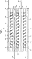
- the reactor 11 comprises a rectangular box enclosure formed between a ceramic cover plate 12 and a ceramic base plate 13.
- Each electrode plate 14, 15, 16, 17 is secured with adhesive between respective pairs of ceramic plates 12, 22; 23, 24; 25, 26; and 27, 13. Where the electrode plates finish short of the edges of the ceramic plates, the space between respective ceramic plates is filled with ceramic adhesive, as for example referenced at 29 ( Figure 2 ).
- the ceramic plates serve as dielectric barrier layers for their associated electrode plates.
- Alumina is a suitable material for the ceramic dielectric barrier material. Aluminium nitride can also be used. However, as an alternative, a glass-ceramic may be used or a micaceous glass such as MICATHERM as described in publication WO 99/20373 .
- the dielectric barrier material can be a catalytic material, or contain a catalytic coating in or on its surface.
- the catalytic material can be produced by ion-exchange, doping, deposited by wet chemical techniques such as sol-gel processing, incipient wetness, by sputtering or by chemical vapour deposition or by thermal spraying for example by plasma spraying or by physical and chemical vapour deposition.
- the type of dielectric barrier material or coating, be it catalytic or non-catalytic can be selected from those described for the packing material.
- Ceramic spacers serve to hold the electrode plates spaced apart and also to form side walls of the rectangular box enclosure.
- openings are provided at 32a, 32b and 32c for gas flow into the reactor (as illustrated by the arrows A in Figure 2 ), and at 33a, 33b, 33c for gas flow out of the reactor (as illustrated by the arrows B in Figure 2 ).
- the ceramic spacers (such as 31) are arranged also to support, in each of the three spaces between the four electrode plates, a layer of material 34a, 34b, and 34c, each of which, in this example, is a sheet of gas permeable filter material providing a surface which extends along the length of the respective gas flow path (32a, 32b and 32c).
- This permeable filter may be in the form of different shapes in order to optimise the trapping of particulate material. It can have indentations with a square wave-form as shown in Figures 1 and 2 but other shapes such as mesh form, or indentations with a triangular form can be used.
- the reactor 11 is connected to the source of gaseous medium to be treated (for example the exhaust gases of a motor vehicle) so that the gaseous medium flows into the reactor through the openings 32a, 32b, 32c in the direction of the arrows A in Figure 2 .
- the gaseous medium is then forced to flow through the layers of filter material 34a, 34b, 34c, in order to exit from the reactor 11 via the openings 33a, 33b, 33c.
- Particulates entrained in the gas flow are trapped on the layers of filter material and are oxidised by the plasma.
- the filter material may alternatively or additionally be such as to trap selected species from the gaseous medium.
- An electrical power supply (not shown) is connected to apply between the pair of electrode plates 15, 17 and the pair of electrode plates 14, 16 a pulsed or alternating potential or direct current of the order of hundreds of volts, kilovolts to tens of kilovolts and (in the case of pulsed or alternating potential) repetition frequencies in the range 50Hz to 50 kHz. It is possible to make the discharge gaps narrow for this embodiment of the invention, that is of the order of 0.5 to 5 millimetres, the dimension transverse to the gap dimension being of the order of 10 to 200 millimetres. A significant advantage follows from the small gap dimension in that the applied voltage required to generate a plasma discharge is reduced and may typically be of the order of 5 kilovolts or less applied across each gas flow path.
- the plasma acts to oxidise particulate trapped on the filter material.
- the reactor 11 can operate above or below atmospheric pressure and from -40°C to 400°C and is thus able to operate at temperatures representative of those found in diesel exhausts from internal combustion engines.
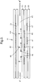
- Figure 3 is in accordance with the invention.
- Figure 3 illustrates a single channel of a modified form of reactor 41.
- Ceramic cover plate 42, upper electrode plate 44, and ceramic dielectric barrier layer 52 are similar to the corresponding components in the example of Figures 1 and 2 .
- the opposed electrode structure defining the opposite side of gas flow path 45 consists of three ceramic dielectric barrier layers 53, 54, 55 between which are sandwiched two electrode grid structures, spaced from one another by the dielectric layer 54.
- the small plate like components 46 of the upper (as seen in the Figure 3 ) electrode grid structure are laterally displaced with respect to the corresponding small plate like components 47 of the lower electrode grid structure.
- the thickness of the various components is exaggerated in all figures including Figure 3 , the dielectric barrier layers 52, 53, 54, 55 being of the order of 0.1 - 5 millimetre thick, preferably 1 mm thick.
- electrode plate 44 is held at a fixed potential, most conveniently ground potential, while the electrode grid structures 46 and 47 are connected to a source of alternating or pulsed or direct potential with respect to the electrode plate 44 such that the potentials applied to the electrode grid structures 46 and 47 are of opposite polarity.
- the effect of this is to create, in addition to a volume discharge across the gap represented by the gas flow path 45, a surface discharge along the surface of the dielectric layer 53.
- the volume discharge is indicated by arrows such as 48 and the surface discharge is indicated by the arrows 49 and is a consequence of the electric fields set up by the difference in potential between the electrode grid structure 46 and the electrode grid structure 47.
- the principal feature of this arrangement is the generation of a surface discharge on the dielectric layer 53, since this surface discharge is particularly effective for assisting the oxidation of particulates trapped on the surface.
- a direct voltage between the electrode plate 44 and the electrode grid structures 46 and 47 together is superimposed in addition to the alternating or pulsed potentials applied separately to the electrode grid structure 46 and electrode grid structure 47.
- This superimposed additional direct voltage is chosen so as electrostatically to charge particulates and thereby encourage their precipitation on the surface of the dielectric layer 53.
- the geometry of the surface in the region of the surface discharge can be arranged to trap particulate by direct impingement, for example by serrating the surface between the buried electrode structures.
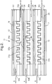
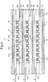
- Figure 4 illustrates how this principle may be applied to a reactor configuration similar to that shown in Figures 1 and 2 .
- components corresponding to those shown in the example of Figures 1 and 2 are referenced with the same reference numerals.
- the volume plasma discharge is set-up between electrode plates 14 and 15, between the electrode plates 15 and 16, and between electrode plates 16 and 17 in the same way as in the example of Figures 1 and 2 .
- the layers of filter material 34a, 34b, 34c have the form of a continuous sheet on one side with upstanding, square-section, ribs on the other. Extending between and along the length of the ribs is an array of insulated metal rod electrodes 61 connected so that adjacent rod electrodes 61 have opposite polarity electric potential applied to them. These rod electrodes 61 serve to provide a surface discharge on the surfaces of the layers of filter material 34a, 34b, 34c.
- the layers of filter material 34a, 34b, 34c need not necessarily have the particular form shown, but may comprise any suitable layer of gas permeable material providing a surface on which particulate matter is trapped as gaseous medium passes therethrough.
- a slice of permeable monolithic foam may be used.
- dielectric barrier layers 22-27 may be apertured to provide an array of so-called triple junctions between the metal electrode, dielectric material and gas which are effective to decrease plasma ignition voltage.
- the work function of the metal is reduced at the point of contact between the metal, insulator and air, the triple junction, due to penetration of the electric field into the insulator (the dielectric material) but not the metal. Electron tunnelling occurs from the metal to the conduction band of the insulator and electrons can be emitted from both the metal and the insulator. Electrical discharge takes place at lower voltage in the composite electrode so that higher plasma currents (plasma energy per litre of plasma) can be obtained. This triple effect increases the number of discharges per unit length of reactor.
- a similar effect may be achieved with the configuration shown in the example of Figure 4 by inverting the layers of filter material 34a, 34b, 34c together with their associated rod electrodes 61, and arranging for the volume discharge electric potential to be applied between the array of rod electrodes 61 and the electrode plate (14, 15,16) now facing the side of the layer of filter material (34a, 34b, 34c respectively) in which the slots containing the electrode rods 61 are open, thus providing an array of effective triple junctions between the filter material (which has, for this purpose, to be of suitable dielectric material), the rod electrodes 61 and the incoming gaseous medium.
- discontinuous metallic film may be in the form of spots or dots (of any circumferential shape, such as circular, rectangular or irregular, even fractal) of metal and can be present on one or more of the dielectric barriers.
- Such added metallic sources of discharge points can also be provided on or in dielectric packing material, where this is also provided in the gas flow path between the electrode.
- dielectric packing material in the form of spheres or other shapes may be provided with surface deposits of thin film metal dots or spots.
- the packing itself may contain a distribution of metallic spheres (or other shapes) in amongst the dielectric packing.
- Such surface metal dots or spots are also advantageous on a dielectric surface for which provision has been made for promoting surface discharge, such as the surface of dielectric layer 53 in Figure 3 or the surfaces of the filter material 34a, 34b, 34c of Figure 4 .
- the location and dimensions of the metal dots or spots must be such that there is not formed a metallic path which would effectively short out the surface discharge path between the electrodes, such as 46, 47 in Figure 3 or adjacent rods 61 in Figure 4 .
- the reactor embodiments described may be installed as part of an emissions control system employing catalysts or other emission control devices for the plasma assisted treatment of the exhaust gases from internal combustion engines.
- emission control devices may comprise exhaust gas recirculation (EGR), variations in ignition timing, fuel ignition timing and fuel injection pulse rate shaping.
- EGR exhaust gas recirculation
Landscapes
- Chemical & Material Sciences (AREA)
- Engineering & Computer Science (AREA)
- Chemical Kinetics & Catalysis (AREA)
- Organic Chemistry (AREA)
- Health & Medical Sciences (AREA)
- Combustion & Propulsion (AREA)
- General Health & Medical Sciences (AREA)
- Toxicology (AREA)
- Physics & Mathematics (AREA)
- Mechanical Engineering (AREA)
- Environmental & Geological Engineering (AREA)
- Plasma & Fusion (AREA)
- Oil, Petroleum & Natural Gas (AREA)
- General Chemical & Material Sciences (AREA)
- Analytical Chemistry (AREA)
- General Engineering & Computer Science (AREA)
- Biomedical Technology (AREA)
- Electromagnetism (AREA)
- Inorganic Chemistry (AREA)
- Physical Or Chemical Processes And Apparatus (AREA)
- Exhaust Gas After Treatment (AREA)
- Treating Waste Gases (AREA)
- Processes For Solid Components From Exhaust (AREA)
Applications Claiming Priority (3)
| Application Number | Priority Date | Filing Date | Title |
|---|---|---|---|
| GB0107020 | 2001-03-21 | ||
| GBGB0107020.0A GB0107020D0 (en) | 2001-03-21 | 2001-03-21 | A reactor for plasma assisted treatment of gaseous media |
| PCT/GB2002/001229 WO2002074435A1 (en) | 2001-03-21 | 2002-03-15 | A reactor for plasma assisted treatment of gaseous |
Publications (2)
| Publication Number | Publication Date |
|---|---|
| EP1372842A1 EP1372842A1 (en) | 2004-01-02 |
| EP1372842B1 true EP1372842B1 (en) | 2020-12-02 |
Family
ID=9911210
Family Applications (1)
| Application Number | Title | Priority Date | Filing Date |
|---|---|---|---|
| EP02718282.3A Expired - Lifetime EP1372842B1 (en) | 2001-03-21 | 2002-03-15 | A reactor for plasma assisted treatment of gaseous |
Country Status (5)
| Country | Link |
|---|---|
| US (1) | US7163663B2 (enExample) |
| EP (1) | EP1372842B1 (enExample) |
| JP (1) | JP4317367B2 (enExample) |
| GB (1) | GB0107020D0 (enExample) |
| WO (1) | WO2002074435A1 (enExample) |
Families Citing this family (31)
| Publication number | Priority date | Publication date | Assignee | Title |
|---|---|---|---|---|
| EP1578524A4 (en) * | 2002-12-13 | 2007-03-28 | Blue Planet Co Ltd | PLASMA REACTOR AND ELECTRODE PLATE USED IN THE SAME |
| DE602004011185T2 (de) | 2003-02-12 | 2008-12-24 | Ngk Insulators, Ltd., Nagoya | Plasmareaktionsgefäss und herstellungsverfahren dafür |
| DE602004031843D1 (de) * | 2003-06-27 | 2011-04-28 | Ngk Insulators Ltd | Plasmaerzeugungselektrode, plasmaerzeugungseinrichtun und abgasreinigungsvorrichtung |
| US7453840B1 (en) | 2003-06-30 | 2008-11-18 | Cisco Systems, Inc. | Containment of rogue systems in wireless network environments |
| JP4637531B2 (ja) * | 2004-08-26 | 2011-02-23 | 京セラ株式会社 | 排気ガス処理用セラミック部材および排気ガス処理装置 |
| DE102005009285B3 (de) * | 2005-02-22 | 2006-09-21 | Deutsches Zentrum für Luft- und Raumfahrt e.V. | Fenstervorrichtung und Verwendung einer Fenstervorrichtung für ein Diagnosesystem für Verbrennungsvorgänge und für eine Brennkammer |
| EP1705965A1 (en) * | 2005-03-21 | 2006-09-27 | Universiteit Gent | Method and system for plasma treatment under high pressure |
| FR2888835A1 (fr) * | 2005-07-25 | 2007-01-26 | Armines Ass Loi De 1901 | Procede de production d'hydrogene a partir d'hydrocarbures ou de composes hydrocarbones |
| US7771672B2 (en) * | 2005-12-17 | 2010-08-10 | Airinspace B.V. | Air purification device |
| US7452410B2 (en) * | 2005-12-17 | 2008-11-18 | Airinspace B.V. | Electrostatic filter having insulated electrodes |
| JP2009519819A (ja) * | 2005-12-17 | 2009-05-21 | エアーインスペース・ビー.ブイ. | 空気浄化装置 |
| US8003058B2 (en) * | 2006-08-09 | 2011-08-23 | Airinspace B.V. | Air purification devices |
| US8544257B2 (en) * | 2007-02-23 | 2013-10-01 | Thomas A. Hamade | Electrically stimulated catalytic converter apparatus, and method of using same |
| US9120073B2 (en) * | 2009-06-05 | 2015-09-01 | Eon Labs, Llc | Distributed dielectric barrier discharge reactor |
| WO2011116174A1 (en) * | 2010-03-17 | 2011-09-22 | Isaac Ray | Electrostatic filter and non-thermal plasma system for air pollution control of hydrocarbon combustion engines |
| CN101912761B (zh) * | 2010-07-05 | 2014-02-19 | 洪昆喨 | 一种均匀电场介电质放电反应器 |
| DE102011078942A1 (de) * | 2011-07-11 | 2013-01-17 | Evonik Degussa Gmbh | Verfahren zur Herstellung höherer Silane mit verbesserter Ausbeute |
| AU2013210889A1 (en) * | 2012-01-20 | 2014-07-24 | University Of Newcastle Upon Tyne | Integrated intensified biorefinery for gas-to-liquid conversion |
| US9676623B2 (en) | 2013-03-14 | 2017-06-13 | Velocys, Inc. | Process and apparatus for conducting simultaneous endothermic and exothermic reactions |
| JP6420697B2 (ja) * | 2014-03-19 | 2018-11-07 | 日本碍子株式会社 | 複合体、ハニカム構造体及び複合体の製造方法 |
| CN105089745B (zh) | 2014-04-17 | 2018-08-14 | 通用电气公司 | 减少废排气中的氮氧化物的系统和方法 |
| GR1009432B (el) | 2015-09-09 | 2019-01-15 | Εθνικο Κεντρο Ερευνας Φυσικων Επιστημων "Δημοκριτος" | Διαταξη ατμοσφαιρικου πλασματος για ομοιομορφη επεξεργασια μεγαλων επιφανειων |
| US11452982B2 (en) | 2015-10-01 | 2022-09-27 | Milton Roy, Llc | Reactor for liquid and gas and method of use |
| US12296313B2 (en) | 2015-10-01 | 2025-05-13 | Milton Roy, Llc | System and method for formulating medical treatment effluents |
| EP3356026B1 (en) | 2015-10-01 | 2022-11-09 | Milton Roy, LLC | Plasma reactor for liquid and gas |
| US10882021B2 (en) | 2015-10-01 | 2021-01-05 | Ion Inject Technology Llc | Plasma reactor for liquid and gas and method of use |
| US10187968B2 (en) | 2015-10-08 | 2019-01-22 | Ion Inject Technology Llc | Quasi-resonant plasma voltage generator |
| US10046300B2 (en) | 2015-12-09 | 2018-08-14 | Ion Inject Technology Llc | Membrane plasma reactor |
| CN111248393B (zh) * | 2020-02-27 | 2023-03-21 | 西安交通大学 | 流体食品协同杀菌装置及方法 |
| CN111786262A (zh) * | 2020-08-25 | 2020-10-16 | 济南国器工程技术有限公司 | 一种气体放电装置和单元和方法 |
| CN116220880A (zh) * | 2023-03-10 | 2023-06-06 | 潍柴动力股份有限公司 | 一种lng发动机尾气处理装置及lng发动机 |
Family Cites Families (22)
| Publication number | Priority date | Publication date | Assignee | Title |
|---|---|---|---|---|
| US4211075A (en) | 1978-10-19 | 1980-07-08 | General Motors Corporation | Diesel engine exhaust particulate filter with intake throttling incineration control |
| US4276066A (en) | 1980-02-25 | 1981-06-30 | General Motors Corporation | Monolith diesel exhaust filter with self-regeneration |
| JPS5765813A (en) | 1980-10-09 | 1982-04-21 | Nippon Soken Inc | Purifier for removing particle from exhaust gas of internal combustion engine |
| JPS6053165B2 (ja) | 1981-03-16 | 1985-11-25 | 株式会社豊田中央研究所 | 内燃機関排気吐煙の捕集装置 |
| US4505107A (en) | 1981-10-26 | 1985-03-19 | Nippondenso Co., Ltd. | Exhaust gas cleaning apparatus |
| US4462812A (en) | 1982-12-08 | 1984-07-31 | General Motors Corporation | Ceramic monolith particulate trap including filter support |
| FR2548264B1 (fr) | 1983-06-16 | 1985-12-13 | Renault | Regeneration des filtres a particules, notamment pour moteurs diesel |
| GB8605058D0 (en) | 1986-02-28 | 1986-04-09 | Porous Element Heating Ltd | Removal of particulate material from gas |
| DE3723544A1 (de) * | 1987-07-16 | 1989-01-26 | Man Technologie Gmbh | Elektrostatischer filter zum reinigen von gasen |
| GB8913978D0 (en) | 1989-06-17 | 1989-08-09 | Atomic Energy Authority Uk | Catalytic treatment |
| GB9301433D0 (en) | 1993-01-20 | 1993-03-17 | Atomic Energy Authority Uk | Gas purification |
| AT397928B (de) * | 1993-03-22 | 1994-08-25 | Panning Peter | Vorrichtung zum abbau von in einem gasstrom enthaltenen schadstoffen |
| DE4416676C2 (de) | 1994-05-11 | 2002-11-07 | Siemens Ag | Vorrichtung zur Entgiftung von Abgasen aus mobilen Anlagen |
| JP4016134B2 (ja) * | 1996-06-13 | 2007-12-05 | 俊介 細川 | ガス処理装置 |
| US5914015A (en) * | 1996-07-15 | 1999-06-22 | Battelle Memorial Institute | Method and apparatus for processing exhaust gas with corona discharge |
| FR2757499B1 (fr) * | 1996-12-24 | 2001-09-14 | Etievant Claude | Generateur d'hydrogene |
| US6517786B1 (en) * | 1997-04-28 | 2003-02-11 | Institute Fuer Niedertemperatur-Plasmaphysik E. V. An Der Ernst-Moritz-Arndt-Universitaet Greifswald | Device and method for decomposing harmful substances contained in flue gas |
| KR100566012B1 (ko) * | 1997-09-09 | 2006-03-30 | 액센투스 피엘씨 | 가스 배출의 처리 |
| GB9722173D0 (en) | 1997-10-22 | 1997-12-17 | Aea Technology Plc | Plasma gas processing device |
| GB9901413D0 (en) * | 1999-01-23 | 1999-03-10 | Aea Technology Plc | Reactor for plasma assisted gas processing |
| GB9911728D0 (en) * | 1999-05-21 | 1999-07-21 | Aea Technology Plc | Dielectric barrier gas reactors with non-axial flow |
| JP2001087620A (ja) * | 1999-09-27 | 2001-04-03 | Ngk Insulators Ltd | 物質処理方法および装置 |
-
2001
- 2001-03-21 GB GBGB0107020.0A patent/GB0107020D0/en not_active Ceased
-
2002
- 2002-03-15 JP JP2002573140A patent/JP4317367B2/ja not_active Expired - Lifetime
- 2002-03-15 WO PCT/GB2002/001229 patent/WO2002074435A1/en not_active Ceased
- 2002-03-15 EP EP02718282.3A patent/EP1372842B1/en not_active Expired - Lifetime
- 2002-03-15 US US10/472,207 patent/US7163663B2/en not_active Expired - Lifetime
Non-Patent Citations (1)
| Title |
|---|
| None * |
Also Published As
| Publication number | Publication date |
|---|---|
| JP4317367B2 (ja) | 2009-08-19 |
| WO2002074435A1 (en) | 2002-09-26 |
| US7163663B2 (en) | 2007-01-16 |
| EP1372842A1 (en) | 2004-01-02 |
| GB0107020D0 (en) | 2001-05-09 |
| US20040094401A1 (en) | 2004-05-20 |
| JP2004533312A (ja) | 2004-11-04 |
Similar Documents
| Publication | Publication Date | Title |
|---|---|---|
| EP1372842B1 (en) | A reactor for plasma assisted treatment of gaseous | |
| US7074370B2 (en) | Plasma assisted reactor | |
| EP1017477B1 (en) | Treatment of gaseous emissions | |
| EP1153207B1 (en) | Reactor for plasma assisted gas processing | |
| JP2000271447A (ja) | 貧排気ガス中に含有されている窒素酸化物の選択的接触還元方法 | |
| US6890495B1 (en) | Plasma-assisted processing of gaseous media | |
| EP1183447A1 (en) | Dielectric barrier gas reactors with non-axial flow | |
| EP1051234B1 (en) | Plasma assisted processing of gas | |
| EP1216746A2 (en) | NOx adsorbent with SOx poisoning protection | |
| US20020034461A1 (en) | Plasma assisted processing of gas | |
| WO2000043102A2 (en) | Process and reactor for plasma assisted gas processing | |
| JPH11347342A (ja) | プラズマ発生装置 | |
| US20030170154A1 (en) | Plasma assisted catalytic treatment of gases |
Legal Events
| Date | Code | Title | Description |
|---|---|---|---|
| PUAI | Public reference made under article 153(3) epc to a published international application that has entered the european phase |
Free format text: ORIGINAL CODE: 0009012 |
|
| 17P | Request for examination filed |
Effective date: 20030911 |
|
| AK | Designated contracting states |
Kind code of ref document: A1 Designated state(s): AT BE CH CY DE DK ES FI FR GB GR IE IT LI LU MC NL PT SE TR |
|
| AX | Request for extension of the european patent |
Extension state: AL LT LV MK RO SI |
|
| 17Q | First examination report despatched |
Effective date: 20040427 |
|
| RAP1 | Party data changed (applicant data changed or rights of an application transferred) |
Owner name: ACCENTUS PLC |
|
| RAP1 | Party data changed (applicant data changed or rights of an application transferred) |
Owner name: QINETIQ LIMITED |
|
| RAP1 | Party data changed (applicant data changed or rights of an application transferred) |
Owner name: QINETIQ LIMITED |
|
| STAA | Information on the status of an ep patent application or granted ep patent |
Free format text: STATUS: EXAMINATION IS IN PROGRESS |
|
| GRAP | Despatch of communication of intention to grant a patent |
Free format text: ORIGINAL CODE: EPIDOSNIGR1 |
|
| STAA | Information on the status of an ep patent application or granted ep patent |
Free format text: STATUS: GRANT OF PATENT IS INTENDED |
|
| INTG | Intention to grant announced |
Effective date: 20200831 |
|
| GRAS | Grant fee paid |
Free format text: ORIGINAL CODE: EPIDOSNIGR3 |
|
| GRAA | (expected) grant |
Free format text: ORIGINAL CODE: 0009210 |
|
| STAA | Information on the status of an ep patent application or granted ep patent |
Free format text: STATUS: THE PATENT HAS BEEN GRANTED |
|
| AK | Designated contracting states |
Kind code of ref document: B1 Designated state(s): AT BE CH CY DE DK ES FI FR GB GR IE IT LI LU MC NL PT SE TR |
|
| REG | Reference to a national code |
Ref country code: GB Ref legal event code: FG4D |
|
| REG | Reference to a national code |
Ref country code: AT Ref legal event code: REF Ref document number: 1340288 Country of ref document: AT Kind code of ref document: T Effective date: 20201215 Ref country code: CH Ref legal event code: EP |
|
| REG | Reference to a national code |
Ref country code: DE Ref legal event code: R096 Ref document number: 60250200 Country of ref document: DE |
|
| REG | Reference to a national code |
Ref country code: IE Ref legal event code: FG4D |
|
| PG25 | Lapsed in a contracting state [announced via postgrant information from national office to epo] |
Ref country code: GR Free format text: LAPSE BECAUSE OF FAILURE TO SUBMIT A TRANSLATION OF THE DESCRIPTION OR TO PAY THE FEE WITHIN THE PRESCRIBED TIME-LIMIT Effective date: 20210303 Ref country code: FI Free format text: LAPSE BECAUSE OF FAILURE TO SUBMIT A TRANSLATION OF THE DESCRIPTION OR TO PAY THE FEE WITHIN THE PRESCRIBED TIME-LIMIT Effective date: 20201202 |
|
| REG | Reference to a national code |
Ref country code: NL Ref legal event code: MP Effective date: 20201202 |
|
| REG | Reference to a national code |
Ref country code: AT Ref legal event code: MK05 Ref document number: 1340288 Country of ref document: AT Kind code of ref document: T Effective date: 20201202 |
|
| PG25 | Lapsed in a contracting state [announced via postgrant information from national office to epo] |
Ref country code: SE Free format text: LAPSE BECAUSE OF FAILURE TO SUBMIT A TRANSLATION OF THE DESCRIPTION OR TO PAY THE FEE WITHIN THE PRESCRIBED TIME-LIMIT Effective date: 20201202 |
|
| PGFP | Annual fee paid to national office [announced via postgrant information from national office to epo] |
Ref country code: GB Payment date: 20210329 Year of fee payment: 20 |
|
| PG25 | Lapsed in a contracting state [announced via postgrant information from national office to epo] |
Ref country code: NL Free format text: LAPSE BECAUSE OF FAILURE TO SUBMIT A TRANSLATION OF THE DESCRIPTION OR TO PAY THE FEE WITHIN THE PRESCRIBED TIME-LIMIT Effective date: 20201202 |
|
| PG25 | Lapsed in a contracting state [announced via postgrant information from national office to epo] |
Ref country code: PT Free format text: LAPSE BECAUSE OF FAILURE TO SUBMIT A TRANSLATION OF THE DESCRIPTION OR TO PAY THE FEE WITHIN THE PRESCRIBED TIME-LIMIT Effective date: 20210405 |
|
| PG25 | Lapsed in a contracting state [announced via postgrant information from national office to epo] |
Ref country code: AT Free format text: LAPSE BECAUSE OF FAILURE TO SUBMIT A TRANSLATION OF THE DESCRIPTION OR TO PAY THE FEE WITHIN THE PRESCRIBED TIME-LIMIT Effective date: 20201202 |
|
| REG | Reference to a national code |
Ref country code: DE Ref legal event code: R097 Ref document number: 60250200 Country of ref document: DE |
|
| REG | Reference to a national code |
Ref country code: DE Ref legal event code: R119 Ref document number: 60250200 Country of ref document: DE |
|
| PLBE | No opposition filed within time limit |
Free format text: ORIGINAL CODE: 0009261 |
|
| STAA | Information on the status of an ep patent application or granted ep patent |
Free format text: STATUS: NO OPPOSITION FILED WITHIN TIME LIMIT |
|
| PG25 | Lapsed in a contracting state [announced via postgrant information from national office to epo] |
Ref country code: MC Free format text: LAPSE BECAUSE OF FAILURE TO SUBMIT A TRANSLATION OF THE DESCRIPTION OR TO PAY THE FEE WITHIN THE PRESCRIBED TIME-LIMIT Effective date: 20201202 Ref country code: IT Free format text: LAPSE BECAUSE OF FAILURE TO SUBMIT A TRANSLATION OF THE DESCRIPTION OR TO PAY THE FEE WITHIN THE PRESCRIBED TIME-LIMIT Effective date: 20201202 |
|
| REG | Reference to a national code |
Ref country code: CH Ref legal event code: PL |
|
| 26N | No opposition filed |
Effective date: 20210903 |
|
| PG25 | Lapsed in a contracting state [announced via postgrant information from national office to epo] |
Ref country code: DK Free format text: LAPSE BECAUSE OF FAILURE TO SUBMIT A TRANSLATION OF THE DESCRIPTION OR TO PAY THE FEE WITHIN THE PRESCRIBED TIME-LIMIT Effective date: 20201202 Ref country code: ES Free format text: LAPSE BECAUSE OF FAILURE TO SUBMIT A TRANSLATION OF THE DESCRIPTION OR TO PAY THE FEE WITHIN THE PRESCRIBED TIME-LIMIT Effective date: 20201202 |
|
| REG | Reference to a national code |
Ref country code: BE Ref legal event code: MM Effective date: 20210331 |
|
| PG25 | Lapsed in a contracting state [announced via postgrant information from national office to epo] |
Ref country code: DE Free format text: LAPSE BECAUSE OF NON-PAYMENT OF DUE FEES Effective date: 20211001 Ref country code: IE Free format text: LAPSE BECAUSE OF NON-PAYMENT OF DUE FEES Effective date: 20210315 Ref country code: FR Free format text: LAPSE BECAUSE OF NON-PAYMENT OF DUE FEES Effective date: 20210331 Ref country code: CH Free format text: LAPSE BECAUSE OF NON-PAYMENT OF DUE FEES Effective date: 20210331 Ref country code: LU Free format text: LAPSE BECAUSE OF NON-PAYMENT OF DUE FEES Effective date: 20210315 Ref country code: LI Free format text: LAPSE BECAUSE OF NON-PAYMENT OF DUE FEES Effective date: 20210331 |
|
| REG | Reference to a national code |
Ref country code: GB Ref legal event code: PE20 Expiry date: 20220314 |
|
| PG25 | Lapsed in a contracting state [announced via postgrant information from national office to epo] |
Ref country code: GB Free format text: LAPSE BECAUSE OF EXPIRATION OF PROTECTION Effective date: 20220314 |
|
| PG25 | Lapsed in a contracting state [announced via postgrant information from national office to epo] |
Ref country code: BE Free format text: LAPSE BECAUSE OF NON-PAYMENT OF DUE FEES Effective date: 20210331 |
|
| PG25 | Lapsed in a contracting state [announced via postgrant information from national office to epo] |
Ref country code: CY Free format text: LAPSE BECAUSE OF FAILURE TO SUBMIT A TRANSLATION OF THE DESCRIPTION OR TO PAY THE FEE WITHIN THE PRESCRIBED TIME-LIMIT Effective date: 20201202 |
|
| PG25 | Lapsed in a contracting state [announced via postgrant information from national office to epo] |
Ref country code: TR Free format text: LAPSE BECAUSE OF FAILURE TO SUBMIT A TRANSLATION OF THE DESCRIPTION OR TO PAY THE FEE WITHIN THE PRESCRIBED TIME-LIMIT Effective date: 20201202 |