EP1372476B1 - Katheter verwendet in einem magnet resonanz abbildungsgerät - Google Patents
Katheter verwendet in einem magnet resonanz abbildungsgerät Download PDFInfo
- Publication number
- EP1372476B1 EP1372476B1 EP02705017A EP02705017A EP1372476B1 EP 1372476 B1 EP1372476 B1 EP 1372476B1 EP 02705017 A EP02705017 A EP 02705017A EP 02705017 A EP02705017 A EP 02705017A EP 1372476 B1 EP1372476 B1 EP 1372476B1
- Authority
- EP
- European Patent Office
- Prior art keywords
- catheter
- transmission
- imaging apparatus
- examined
- image
- Prior art date
- Legal status (The legal status is an assumption and is not a legal conclusion. Google has not performed a legal analysis and makes no representation as to the accuracy of the status listed.)
- Expired - Lifetime
Links
Images


Classifications
-
- G—PHYSICS
- G01—MEASURING; TESTING
- G01R—MEASURING ELECTRIC VARIABLES; MEASURING MAGNETIC VARIABLES
- G01R33/00—Arrangements or instruments for measuring magnetic variables
- G01R33/20—Arrangements or instruments for measuring magnetic variables involving magnetic resonance
- G01R33/28—Details of apparatus provided for in groups G01R33/44 - G01R33/64
- G01R33/285—Invasive instruments, e.g. catheters or biopsy needles, specially adapted for tracking, guiding or visualization by NMR
- G01R33/287—Invasive instruments, e.g. catheters or biopsy needles, specially adapted for tracking, guiding or visualization by NMR involving active visualization of interventional instruments, e.g. using active tracking RF coils or coils for intentionally creating magnetic field inhomogeneities
-
- A—HUMAN NECESSITIES
- A61—MEDICAL OR VETERINARY SCIENCE; HYGIENE
- A61B—DIAGNOSIS; SURGERY; IDENTIFICATION
- A61B5/00—Measuring for diagnostic purposes; Identification of persons
- A61B5/06—Devices, other than using radiation, for detecting or locating foreign bodies ; Determining position of diagnostic devices within or on the body of the patient
-
- A—HUMAN NECESSITIES
- A61—MEDICAL OR VETERINARY SCIENCE; HYGIENE
- A61B—DIAGNOSIS; SURGERY; IDENTIFICATION
- A61B5/00—Measuring for diagnostic purposes; Identification of persons
- A61B5/06—Devices, other than using radiation, for detecting or locating foreign bodies ; Determining position of diagnostic devices within or on the body of the patient
- A61B5/065—Determining position of the probe employing exclusively positioning means located on or in the probe, e.g. using position sensors arranged on the probe
Definitions
- the invention relates to a catheter for use during examination of an object by means of a magnetic resonance (MR) imaging apparatus.
- the invention also relates to a method of forming an MR image and of visualizing a position of a catheter, introduced into an object to be examined, in the MR image, as well as to an MR imaging apparatus for carrying out such a method.
- MR magnetic resonance
- magnetic resonance imaging apparatus are used not only for the examination but also for the treatment of a patient.
- a catheter is then introduced into the patient, and it must be possible to localize the catheter in the MR image.
- the catheter is generally made of materials which are not visible in an MR image, steps must be taken so as to ensure that notably the tip of the catheter can be reliably recognized without affecting the patient.
- Active switches for example, diodes which are switched in the resonant circuit for this purpose degrade the quality factor of the resonant circuit further, so that the magnetization (flip angle of the nuclear spins) is changed to a very small degree only, that is, notably in the case of complex body structures. Furthermore, the quality factor of the resonant circuit is particularly poor in the case of low field strengths, because the coil losses are then proportionally higher.
- EP 0 531 081 discloses an active system in which the catheter is provided with a transmission coil which is connected to an RF source and is fed with a comparatively low power, so that the coil generates an electromagnetic dipole field which is picked up by external receiving coils and evaluated so as to determine or track the position of the catheter.
- This active system has a drawback in that, in addition to the catheter, wires which carry RF voltages must be introduced into the patient so as to supply the transmission coil with the RF power. This may give rise to undesirable heating of the tissue in the vicinity of the wires, so that operation can take place with a comparatively small power only.
- the amount of calculation work necessary for determining a suitably accurate position is comparatively large.
- the RF power emitted by the wires could cause disturbances in the MR image.
- first method as defined in claim 7 or by a second method as defined in claim 8.
- first method is generally to be preferred, for given applications it may also be useful to operate the RF coil and the transmission unit of the catheter simultaneously in conformity with the second method, for example, in order to carry out specific examinations during localization of the (moving) catheter.
- a special advantage of the first method resides in the fact that, because of the alternating modes of operation, mutual influencing or disturbing of the imaging on the one hand and the localizing of the catheter on the other hand is practically precluded.
- the near field mentioned in the above claims is to be understood to mean the zone which is enclosed by the transmission antenna as well as the zone outside the transmission antenna in which the RF field of the antenna is essentially concentrated.
- the foregoing solutions combine the advantages of passive and active systems, without having to accept the essential drawbacks thereof.
- the accuracy of localization is exactly as high as in the case of the described passive system, but the local nuclear magnetization, and hence also the MR relaxation signal to be acquired, is essentially higher because of the active excitation.
- the means required for evaluating the signal received are significantly less than in the case of the described active system, because the signal is picked up by the RF receiving coils which are present in an MR imaging apparatus any way and can be processed and reproduced by the devices present therein,
- the embodiment disclosed in the claims 2 and 5 offer special advantages in respect of ease of manufacture of a catheter in accordance with the invention.
- the embodiment in conformity with claim 3 enables measurements to be performed at the same time in the tissue of a patient which surrounds the catheter, the measuring values being transferred preferably by means of a method as claimed in claim 9.
- the embodiments disclosed in the claims 4 and 6 are particularly advantageous with a view to the use of the catheter without complications, whereas a method as claimed in claim 10 even enables the supply lead through the catheter to be dispensed with.
- the claims 11 and 12 describe a magnetic resonance imaging apparatus which is particularly suitable for carrying out the method.
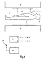
- Fig. 1 shows the essential components of an MR imaging apparatus which relate to the generating and acquisition of magnetic fields in an examination zone 1.
- respective magnet systems 2, 3 which serve to generate a basic magnetic field (B 0 field) as well as gradient magnetic fields in known manner.
- the basic magnetic field traverses a patient P essentially in a direction perpendicular to the longitudinal axis of the patient (that is, generally in the vertical direction).
- Flat, or at least flattish, RF conductor structures in the form of RF transmission coils 4 and RF receiving coils 5 serve to generate RF pulses (B 1 field) whereby the nuclear spins are excited in the tissue to be examined as well for the detection of subsequent MR relaxation processes in the tissue, said RF transmission and receiving coils being arranged on the magnet systems 2 and 3, respectively; additionally, or alternatively, a local RF receiving coil 6 may also enclose the part of the patient P to be examined.
- the catheter in accordance with the invention can also be used in axial systems in which the basic magnetic field traverses the patient essentially in the direction of the longitudinal axis of the patient.
- Such systems are known per se and comprise a tubular examination space in which the patient is introduced in the axial direction.
- a catheter 10 is often use to perform a treatment on the patient P or to take a tissue sample, the catheter being introduced into the patient and its position being visualized on a display screen.
- a switching unit 41 which is connected to the catheter 10 by way of a first output A and to the RF transmission coils 4 by way of a second output B.
- the catheter 10 and the RF transmission coils 4 can be manually or automatically controlled by means of the switching unit in such a manner that they are alternately or essentially simultaneously operative in the manner to be described hereinafter.
- the alternating mode In the alternating mode (first method), switching over takes place between two modes of operation.
- the RF transmission coil 4 of the MR imaging apparatus In the first mode of operation, the RF transmission coil 4 of the MR imaging apparatus is operative in known manner so as to form an MR image of the object to be examined; and the transmission unit 11 of the catheter 10 is switched off.
- the RF transmission coil 4 is switched off.
- an activated transmission unit arranged at the tip of the catheter excites a local nuclear magnetization (that is, in the near field of a transmission antenna of the catheter) by emission of RF pulses of a first frequency f 1 , and the resultant MR relaxation events are received by the RF receiving coils 5, 6.
- the signal received serves to reproduce the position of the catheter tip in the MR image.
- the RF transmission coils of the MR imaging apparatus and the transmission unit of the catheter are activated essentially simultaneously, so that an intensified nuclear magnetization is excited in the near field of the transmission antenna; such intensified nuclear magnetization is detected by the RF receiving coils 5, 6 and is reproduced in the MR image formed so as to visualize the position of the catheter.
- the transmission unit may also include sensors for picking up given properties of the surrounding tissue.
- the measuring values of the sensors are applied, by way of modulation and emission of electromagnetic waves of a second frequency f 2 (or of acoustic or optical waves), to a receiving and evaluation unit 42 which includes a receiving antenna array 7x, 8x (see Figs. 13 and 14 ) so as to be further processed or displayed in known manner.
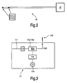
- Fig. 2 is a diagrammatic representation of a catheter 10 in accordance with the invention.
- a microchip 11 (additionally shown at an enlarged scale) which includes the transmission unit.
- the microchip includes all components necessary for generating RF electromagnetic waves.
- a supply and control unit 12 via which a supply and control lead which is guided through the catheter is connected to the microchip 11.
- Fig. 3 shows a block diagram of the microchip 11.
- the microchip includes an energy converter 112 which is connected to the supply and control lead 111 and supplies a preferably voltage-controlled RF oscillator 113 (VCO) with a suitable supply voltage.
- the RF oscillator 113 is also controlled via the lead 111 and includes a switch-off unit 113a.
- An output of the RF oscillator is connected to at least one transmission antenna 116 for the emission of the generated electromagnetic waves of a first frequency f 1 .
- the first frequency f 1 serves to generate a local B 1 field whereby a nuclear magnetization is excited in the tissue in the near field of the transmission antenna 116.
- Also provided on the microchip 11 are one or more sensors 114 for picking up temperatures, pressures, pH-values or other parameters of the surrounding tissue.
- the output signals of the sensors are applied to a modulator 115 for modulating the frequency, amplitude and/or phase of the electromagnetic waves of a second frequency f 2 which are generated by the RF oscillator 113, so that the sensor signals can be transmitted in a wireless manner, via the transmission antenna 116, to the receiving and evaluation unit 42, situated outside the patient, so as to be evaluated for diagnostic purposes.
- a sensor may also be a resonant circuit 114a or an inductance such as, for example, a separate MR receiving coil whereby the MR relaxation process or processes in the near field of the sensor subsequent to the excitation with the first frequency f 1 are picked up.
- This sensor 114a is connected to the input of a preamplifier 115a whose output is connected to the oscillator 113, so that the excited MR relaxation events can also be emitted, via the transmission antenna 116, in the form of a suitable modulation of the second frequency f 2 , that is, if they are not picked up by the RF receiving coils 5, 6.
- the catheter should be localized by direction finding of the receiving direction in different projections; preferably a plurality of suitably arranged receiving antennas is used for this purpose.
- a common transmission antenna 116 can be used for the two frequencies.
- the transmission antenna for the first frequency can also serve as the sensor 114a for picking up the MR relaxation events.
- the oscillator may be constructed, for example as a Colpits oscillator or a Hartley oscillator and includes one or more resonant circuits as well as a switch-off unit 113a (essentially a diode) for switching off the resonant circuits so as to avoid induction phenomena when the RF transmission coils 4 emit RF pulses (generating the B 1 field) in order to excite the nuclear spins in the object to be examined.
- a switch-off unit 113a essentially a diode
- the transmission antenna 116 may be formed by one or more microcoils which form, in conformity with Fig. 5 , either a short rod antenna (a) or are connected, for example, so as to form a parallel resonant circuit (b) which is capacitively coupled to the oscillator 113. These coils are preferably wound directly around the tip of the catheter, that is, separate from the microchip ( Figs. 8 to 11 ).
- the microchip 11 is formed, for example, as a silicon chip in a bipolar technique or on the basis of a glass or a ceramic material.
- a chip of this kind occupying a surface area of no more than from approximately 1 to 4 mm 2 , can be integrated directly in the tip of the catheter and is diagrammatically shown in a plan view in Fig. 6 .
- Various assemblies which form respective electronic functional units are indicated on the chip. These functional units include the oscillator 113 which receives electric power via the energy converter 112, a sensor and modulator unit 114, 115 which includes one or more sensors with associated measuring data modulators, the preamplifier 115a as well as the switch-off unit 113a for the oscillator 113 or the transmission antenna 116. Furthermore, one or more inductances (planar, coils) L and capacitances C, constituting one or more resonant circuits of the oscillator 113, are also printed as appropriate conductor tracks on the chip 11.
- the power supply and control of the microchip 11 take place via the supply and control lead 111, various embodiments of which are shown in Fig. 7 .
- this lead is formed by a thin wire as shown in Fig. 7(a) .
- the supply lead 111 is preferably made of resistance wire alloys having a resistance of more than 500 ohms/m.
- ⁇ wavelength of the emitted energy
- a plurality of diodes 111a may be connected in series in the supply lead as shown in Fig. 7(b) so as to avoid that it tends to resonate.
- a plurality of serial fuses 111b is provided so as to interrupt the lead when a limit current is exceeded.
- a plurality of inductances 111c may also be connected in series in the supply lead.
- Fig. 7(e) shows a further embodiment of the supply lead 111.
- This lead forms a coaxial cable which comprises an inner conductor 111d enclosed by an outer conductor 111e which is formed as a shield.
- a plurality of ⁇ /4 leads 111f is arranged along the coaxial cable, one end of said ⁇ /4 leads being connected to the outer conductor 111e whereas their other end is open.
- the coaxial cable and the ⁇ /4 leads preferably are also enclosed by an insulating sheath 111g. The propagation of RF currents via the supply lead, and hence the risk of resonances, is avoided again in this embodiment.
- Fig. 7(f) shows a further version of the supply lead shown in Fig. 7(b) . It is a coaxial lead in the inner conductor 111d of which a first plurality of diodes 111h is connected in series in a first current direction, whereas a second plurality of diodes 111k which are connected in series in a second, opposite current direction is inserted in the outer conductor 111e.
- the first diodes 111h and the second diodes 111k are arranged so as to be offset relative to one another.
- the supply lead 111 may also be an optical fiber.
- the energy converter 112 is an optoelectronic converter which forms the necessary supply voltage from the light.
- the supply lead 111 is suitable not only for the transfer of energy, but also for the control of the microchip and notably of the RF oscillator (VCO) so as to switch over between the first and the second frequency.
- VCO RF oscillator
- the microchip 11 can also be inductively supplied with the necessary power.
- the field of the RF transmission coil 4 can be used to induce a voltage in the transmission antenna 116 (or another inductance), said voltage being capacitively stored and used to operate the microchip.
- the supply lead 111 serves only for the control of the VCO 113.
- the transmission power of the oscillator 113 is then smaller, of course, it generally suffices at least in the cases where use is made of an RF receiving coil 6 which is arranged directly around the part of the patient to be examined.
- Fig. 8 is a diagrammatic cross-sectional view of the front part of a catheter 10 and its tip.
- a catheter sleeve 10a enclosing a catheter lumen 10b, accommodates the supply lead 111 (denoted by dashed lines).
- the lead terminates at the microchip 11 which is also accommodated in the catheter sleeve 10a.
- a microcoil NMR coil which serves as a transmission antenna 116 and whose turns are also situated in the catheter sleeve 10a is wound around the catheter.
- the tip of the catheter may also be constructed as an expansion catheter 101 as shown in Fig. 9 .
- the turns of the coil 116 are provided in a wall 101a of the expansion catheter which is in known manner slid out of the catheter sleeve 10a so as to be expanded subsequently by means of a pulling wire 102 which extends through the catheter as far as its other end, or to be expanded automatically.
- the microchip 11 which is supplied with electric power and is controlled via the supply lead 111, in this case extending through the catheter lumen 10b, is again diagrammatically indicated in this representation.
- Fig. 10 shows a further embodiment of the tip of the catheter which is formed by two orthogonal expansion catheters 101, 101', in the walls 101a of which there are again provided turns of one or more microcoils 116.
- the expansion catheters 101, 101' may also be expanded by way of the pulling wire 102 or automatically when slid out of the catheter sleeve 10a.
- the expansion catheter can be formed in such a manner that it is at the same time rotated about its longitudinal axis when the pulling wire 102 is pulled, so that it assumes a helix-like shape.
- the effect of the microcoils 116 can thus be optimized.
- the microchip 11 as well as the supply lead 111 and the pulling wire 102 which extend through the lumen 10b of the catheter are diagrammatically indicated again in this representation.
- Fig. 11 shows this expansion catheter and other expansion catheters once more in separate views.
- a coil-like expansion catheter Fig. 11c
- a multi-loop expansion catheter Fig. 11d
- the type of expansion catheter is chosen not only in dependence on the organ to be treated, but also with a view to achieving an optimum effect, that is, optimum nuclear magnetization, of the microcoils 116 formed by the individual loops.
- Fig. 12(a) shows the relative position of the two frequencies produced by the RF oscillator 113, that is, the first frequency f 1 (NMR frequency) of RF pulses for generating the B 1 field whereby nuclear magnetization is excited in a near field around the transmission antenna (or the microcoil (coils)) 116, as well as the second frequency f 2 of an RF carrier whereby the measuring values and data picked up by the sensors 114, 114a are transferred to the receiving and evaluation unit 42 by frequency, amplitude or phase modulation.
- the first frequency f 1 is dependent on the strength of the basic magnetic field and lies between approximately 8 and 128 MHz for a range of the field strength of between 0.2 and 3 Tesla.
- the second frequency f 2 may also be higher than the first frequency f 1 , and each frequency may also be associated with a respective transmission antenna 116 and be connected to the oscillator output accordingly.
- Fig. 12(b) also shows a typical short burst pulse with which the oscillator 113 emits electromagnetic waves of the first frequency f 1 .
- the phase, the amplitude and the on/off times of the RF pulse as well as the bandwidth of the burst pulse can be varied so as to excite, by way of a corresponding adjustment of these variables, a nuclear magnetization to a different degree (for example, in dependence on the location in which the catheter is situated within the patient) or in an optimized manner.
- switching over between two modes of operation preferably takes place in an alternating fashion.
- the MR imaging apparatus is operative so as to form an MR image of the region to be examined in known manner, that is, the nuclear spins aligned by the basic magnetic field (B 0 field) are deflected, by the RF pulses (B 1 field) generated by the RF transmission coils 4, through a so-called flip angle (excitation by nuclear magnetization) and the subsequent relaxation events are detected by the RF receiving coils 5, 6 and localized so as to perform imaging by means of the gradient magnetic fields.
- the resonant circuit L, C of the oscillator 113 as well as preferably the transmission antenna 116 are then interrupted or separated from the oscillator by the switch-off unit 113, so that no currents can be induced therein.
- the voltage induced in the transmission antenna 116 of the microchip 11 can be capacitively stored.
- the catheter 10 introduced into the patient is localized and reproduced in the MR image.
- the RF transmission coils 4 are inactive and the VCO oscillator 113 is controlled in such a manner that the emission of electromagnetic waves of the first frequency f 1 , that is, in the form of burst pulses (B 1 field), excites nuclear magnetization in the near field of the transmission antenna 116 (for example, a microcoil).
- the subsequent MR relaxation events are picked up again by the RF receiving coils 5, 6, localized by means of the gradient magnetic fields and reproduced in the MR image formed in the first mode of operation.
- the amplitude, the frequency and/or the phase of the burst pulses preferably are adjustable.
- the second frequency f 2 is amplitude modulated, frequency modulated and/or phase modulated, that is, by means of the measuring data modulator 115, with the measuring data picked up by the sensors 114, 114a so as to be emitted.
- Switching over between the first frequency and the second frequency preferably takes place in an alternating fashion by appropriate control of the (voltage-controlled) RF oscillator 113 via the supply lead 111.
- a plurality of local receiving antennas 7x, 8x is provided in the case of a vertical system as shown in the Figs. 13 and 14 , each of said antennas being arranged at the periphery of a first planar RF shield 71 and a second planar RF shield 81, thus constituting a first antenna array 7 and a second antenna array 8.
- the RF shields 71, 81 are situated above and below the patient P in the examination space 1, that is, essentially at the area where the RF transmission coil 4 and the receiving coil 5 are arranged.
- FIG. 13 is a longitudinal sectional view of the tubular examination space in the case of an axial system of the kind set forth.
- Each of the receiving antennas 7x, 8x is connected to a diversity switch 9 whereby switching over to the receiving antenna which is each time nearest to the catheter takes place.
- the demodulation and the evaluation of the received measuring data take place by means of the receiving and evaluation unit 42 ( Fig. 1 ) and while utilizing a method that is known per se.
Landscapes
- Health & Medical Sciences (AREA)
- Life Sciences & Earth Sciences (AREA)
- Physics & Mathematics (AREA)
- Engineering & Computer Science (AREA)
- Pathology (AREA)
- General Health & Medical Sciences (AREA)
- Molecular Biology (AREA)
- Human Computer Interaction (AREA)
- Heart & Thoracic Surgery (AREA)
- Medical Informatics (AREA)
- Biophysics (AREA)
- Surgery (AREA)
- Animal Behavior & Ethology (AREA)
- Biomedical Technology (AREA)
- Public Health (AREA)
- Veterinary Medicine (AREA)
- Condensed Matter Physics & Semiconductors (AREA)
- General Physics & Mathematics (AREA)
- Magnetic Resonance Imaging Apparatus (AREA)
- Materials For Medical Uses (AREA)
- Media Introduction/Drainage Providing Device (AREA)
Claims (12)
- Katheter für die Verwendung während der Untersuchung eines Objekts mittels eines MR-Bildgebungsgeräts mit einer HF-Sendespule (4), wobei am Katheter (10) eine Sendeeinheit (11) zum Erzeugen hochfrequenter Schwingungsimpulse einer ersten Frequenz (f1) und eine Sendeantenne (116) zum Emittieren der hochfrequenten Schwingungsimpulse angebracht sind, wodurch im Nahfeld der Sendeantenne eine Kernmagnetisierung im zu untersuchenden Objekt dergestalt angeregt wird, dass die genannte Magnetisierung von einer HF-Empfangsspule (5, 6) des MR-Bildgebungsgeräts aufgenommen und in einem MR-Bild wiedergegeben werden kann, um eine Position des Katheters sichtbar zu machen.
- Katheter nach Anspruch 1, dadurch gekennzeichnet, dass die Sendeeinheit durch einen Mikrochip (11) gebildet wird, der einen Oszillator (113) enthält und in einer Wand (10a) des Katheters untergebracht ist.
- Katheter nach Anspruch 2, dadurch gekennzeichnet, dass der Mikrochip (11) sowohl mindestens einen Sensor (114, 114a) zur Erfassung von Messwerten des zu untersuchenden Objekts als auch einen Modulator (115) zum Modulieren hochfrequenter Schwingungen einer zweiten vom Oszillator (113) erzeugten Frequenz (f2) enthält, wobei die Messwerte des Sensors dergestalt sind, dass sie zur Auswertung an eine Empfangs- und Auswertungseinheit (42) übertragen werden können, die sich außerhalb des zu untersuchenden Objekts befindet.
- Katheter nach Anspruch 1, dadurch gekennzeichnet, dass die Sendeeinheit (11) über eine Leitung (111), die durch den Katheter (10) geführt wird, mit einer Stromversorgungs- und/oder Steuereinheit (12) verbunden ist, die sich außerhalb des zu untersuchenden Objekts befindet.
- Katheter nach Anspruch 1, dadurch gekennzeichnet, dass die Sendeantenne durch mindestens eine Mikrospule (116) gebildet wird, die um den Katheter (10) gewickelt ist.
- Katheter nach Anspruch 1, dadurch gekennzeichnet, dass die Spitze des Katheters als ein Expansionskatheter (100, 101') ausgeführt ist und die Sendeantenne (116) durch Wicklungen mindestens einer Mikrospule gebildet wird, die sich in Wänden (101a) des Expansionskatheters erstrecken.
- Verfahren sowohl zum Erzeugen eines MR-Bildes eines zu untersuchenden Objekts mittels eines Magnetresonanz-Bildgebungsgeräts als auch zum Visualisieren der Position eines in das zu untersuchende Objekt eingeführten Katheters (10) nach Anspruch 1 in dem MR-Bild, gekennzeichnet dadurch, dass das Umschalten zwischen einer ersten Betriebsart und einer zweiten Betriebsart in abwechselnder Weise stattfindet, wobei die HF-Sendespule (4) des MR-Bildgebungsgeräts arbeitet, um in der ersten Betriebsart ein MR-Bild des zu untersuchenden Objekts zu erzeugen, während die Sendeeinheit (11) des Katheters (10) ausgeschaltet ist, während in der zweiten Betriebsart die HF-Sendespule (4) ausgeschaltet ist und die Sendeeinheit (11) des Katheters arbeitet, um im Nahfeld der Sendeantenne (16) eine Kernmagnetisierung anzuregen, die vom MR-Bildgebungsgerät erfasst und in dem in der ersten Betriebsart erzeugten MR-Bild wiedergegeben wird, wodurch die Position des Katheters sichtbar gemacht wird.
- Verfahren sowohl zum Erzeugen eines MR-Bildes eines zu untersuchenden Objekts mittels eines Magnetresonanz-Bildgebungsgeräts als auch zum Visualisieren der Position eines in das zu untersuchende Objekt eingeführten Katheters (10) nach Anspruch 1, gekennzeichnet dadurch, dass die HF-Sendespule (4) des MR-Bildgebungsgeräts und die Sendeeinheit (11) des Katheters (10) im Wesentlichen simultan arbeiten, so dass im Nahfeld der Sendeantenne (16) eine verstärkte Kernmagnetisierung angeregt wird, die vom MR-Bildgebungsgerät erfasst und im erzeugten MR-Bild wiedergegeben wird, wodurch die Position des Katheters sichtbar gemacht wird.
- Verfahren nach Anspruch 7 oder 8, dadurch gekennzeichnet, dass während des Betriebs der Sendeeinheit (11) des Katheters (10) das Umschalten zwischen einer ersten und einer zweiten Frequenz (f1, f2) auf abwechselnde Weise stattfindet, wobei die erste Frequenz (f1) so gewählt wird, dass die Kernmagnetisierung im Nahfeld der Sendeantenne (116) angeregt wird, und die zweite Frequenz (f2) dazu dient, von Sensoren (114, 114a) erfassten Messwerte des zu untersuchenden Objekts an eine Empfangs- und Auswertungseinheit (42) zu übertragen.
- Verfahren nach Anspruch 7 oder 8, dadurch gekennzeichnet, dass während des Betriebs der Sendespule (4) eine Spannung in eine Induktivität der Sendeeinheit (11) induziert wird, wobei die genannte Spannung einen Kondensator auflädt, der als Versorgungsspannungsquelle für die Sendeeinheit (11) während des Betriebs dieser Einheit dient.
- Magnetresonanz-Bildgebungsgerät zum Ausführen des Verfahrens nach Anspruch 7 oder 8, dadurch gekennzeichnet, dass es eine Umschalteinheit (41) zum manuellen und/oder automatischen Aktivieren des Betriebs der HF-Sendespule (4) und der Sendeeinheit (11) beinhaltet, das heißt in einer abwechselnden oder im Wesentlichen simultanen Weise.
- Magnetresonanz-Bildgebungsgerät zum Ausführen des Verfahrens nach Anspruch 9, dadurch gekennzeichnet, dass es eine Empfangs- und Auswertungseinheit (42) mit einem Empfangsantennenarray (7x, 8x) zum Empfangen und Auswerten der Messwerte von den Sensoren (114, 114a) beinhaltet, die von der Sendeeinheit (11) mit der zweiten Frequenz (f2) ausgegeben werden.
Applications Claiming Priority (3)
| Application Number | Priority Date | Filing Date | Title |
|---|---|---|---|
| DE10113661A DE10113661A1 (de) | 2001-03-21 | 2001-03-21 | Katheter zur Anwendung in einem Magnetresonanz-Bildgerät |
| DE10113661 | 2001-03-21 | ||
| PCT/IB2002/000876 WO2002074164A1 (en) | 2001-03-21 | 2002-03-19 | Catheter for use in a magnetic resonance imaging apparatus |
Publications (2)
| Publication Number | Publication Date |
|---|---|
| EP1372476A1 EP1372476A1 (de) | 2004-01-02 |
| EP1372476B1 true EP1372476B1 (de) | 2008-05-21 |
Family
ID=7678330
Family Applications (1)
| Application Number | Title | Priority Date | Filing Date |
|---|---|---|---|
| EP02705017A Expired - Lifetime EP1372476B1 (de) | 2001-03-21 | 2002-03-19 | Katheter verwendet in einem magnet resonanz abbildungsgerät |
Country Status (5)
| Country | Link |
|---|---|
| US (1) | US20030135110A1 (de) |
| EP (1) | EP1372476B1 (de) |
| JP (2) | JP4004962B2 (de) |
| DE (2) | DE10113661A1 (de) |
| WO (1) | WO2002074164A1 (de) |
Cited By (1)
| Publication number | Priority date | Publication date | Assignee | Title |
|---|---|---|---|---|
| EP4493946A4 (de) * | 2022-03-18 | 2026-04-01 | Transmural Systems Llc | Verbesserte verfahren, systeme und maschinenlesbare programme für magnetresonanz |
Families Citing this family (54)
| Publication number | Priority date | Publication date | Assignee | Title |
|---|---|---|---|---|
| DE10151779A1 (de) * | 2001-10-19 | 2003-05-08 | Philips Corp Intellectual Pty | Verfahren zum Lokalisieren eines Gegenstandes in einer MR-Apparatur sowie Katheter und MR-Apparatur zur Durchführung des Verfahrens |
| AU2003207615A1 (en) * | 2002-01-18 | 2003-12-02 | Std Manufacturing, Inc. | Ablation technology for catheter based delivery systems |
| US20030206019A1 (en) * | 2002-05-02 | 2003-11-06 | Boskamp Eddy B. | Wireless RF module for an MR imaging system |
| US20060052692A1 (en) * | 2002-12-13 | 2006-03-09 | Steffen Weiss | Method and arrangement for determining the position of an object in an mr device |
| US7440792B2 (en) | 2003-02-05 | 2008-10-21 | Koninklijke Philips Electronics N.V. | MR visualization of interventional devices |
| US20040230114A1 (en) * | 2003-03-18 | 2004-11-18 | Clatterbaugh Guy V. | MRI flex circuit catheter imaging coil |
| EP1488738A1 (de) * | 2003-06-19 | 2004-12-22 | Instrumentarium Corporation | Patientenkabel für medizinische Messungen |
| WO2005024447A1 (en) * | 2003-09-09 | 2005-03-17 | Koninklijke Philips Electronics, N.V. | Catheter tip tracking for interventional procedures monitored by magnetic resonance imaging |
| JP4846582B2 (ja) * | 2003-09-12 | 2011-12-28 | コーニンクレッカ フィリップス エレクトロニクス エヌ ヴィ | マイクロコイルを備える医療機器の位置を突きとめるための方法 |
| GB0405552D0 (en) * | 2004-03-12 | 2004-04-21 | Magnet Attraction Ltd | Methods for the targetted delivery of biological molecules |
| CN1947027B (zh) * | 2004-04-26 | 2011-04-06 | 皇家飞利浦电子股份有限公司 | 电-光磁共振换能器 |
| EP1830703B1 (de) * | 2004-12-22 | 2016-07-06 | Philips Intellectual Property & Standards GmbH | Anordnung zum bestimmen der räumlichen verteilung von magnetischen teilchen |
| US7585280B2 (en) | 2004-12-29 | 2009-09-08 | Codman & Shurtleff, Inc. | System and method for measuring the pressure of a fluid system within a patient |
| DE102005003171A1 (de) * | 2005-01-19 | 2006-08-03 | Biotronik Crm Patent Ag | Katheter mit drahtloser Datenübertragung |
| EP3155966B1 (de) | 2005-01-31 | 2018-07-04 | Mediguide Ltd. | Verfahren und system zur beseitigung von elektromagnetischer interferenz in einem medizinischen bild in echtzeit |
| AU2006200951B2 (en) † | 2005-03-13 | 2012-01-19 | Integra LifeSciences Switzerland Sarl | Pressure sensing devices |
| US10362947B2 (en) * | 2005-03-15 | 2019-07-30 | Integra LifeSciences Switzerland Sarl | Pressure sensing devices |
| US20060211945A1 (en) * | 2005-03-15 | 2006-09-21 | Codman & Shurtleff, Inc. | Pressure sensing methods |
| US7510533B2 (en) * | 2005-03-15 | 2009-03-31 | Codman & Shurtleff, Inc. | Pressure sensing valve |
| AU2012200359B2 (en) * | 2005-03-13 | 2013-09-19 | Integra LifeSciences Switzerland Sarl | Pressure sensing devices |
| US7236567B2 (en) * | 2005-03-24 | 2007-06-26 | Siemens Aktiengesellschaft | Method and apparatus for synchronizing operation of an x-ray system and a magnetic system |
| US7309989B2 (en) * | 2005-04-06 | 2007-12-18 | General Electric Company | Wireless RF coil power supply |
| JP2006334238A (ja) * | 2005-06-03 | 2006-12-14 | Isao Shimoyama | Mri装置用送受信素子、mri装置用送受信素子アレイ及び内視鏡 |
| DE102006044659A1 (de) * | 2005-09-21 | 2007-03-22 | Siemens Ag | Temperatursonde zur Einführung in die Speiseröhre |
| US20070156042A1 (en) * | 2005-12-30 | 2007-07-05 | Orhan Unal | Medical device system and method for tracking and visualizing a medical device system under MR guidance |
| US8457712B2 (en) * | 2005-12-30 | 2013-06-04 | Wisconsin Alumni Research Foundation | Multi-mode medical device system and methods of manufacturing and using same |
| GB0603637D0 (en) * | 2006-02-23 | 2006-04-05 | Univ Ulster | Tube monitoring system |
| US8526688B2 (en) * | 2006-03-09 | 2013-09-03 | General Electric Company | Methods and systems for registration of surgical navigation data and image data |
| DE102006034389B4 (de) * | 2006-07-25 | 2018-06-07 | Siemens Healthcare Gmbh | Katheter zum Einsatz bei Magnet-Resonanz-unterstützten interventionellen Verfahren |
| CN101495881B (zh) | 2006-08-02 | 2013-05-01 | 皇家飞利浦电子股份有限公司 | 在rf场中使用的传输路径 |
| US8368402B2 (en) | 2006-11-08 | 2013-02-05 | T2 Biosystems, Inc. | NMR systems for in vivo detection of analytes |
| US8532742B2 (en) * | 2006-11-15 | 2013-09-10 | Wisconsin Alumni Research Foundation | System and method for simultaneous 3DPR device tracking and imaging under MR-guidance for therapeutic endovascular interventions |
| US20080183070A1 (en) * | 2007-01-29 | 2008-07-31 | Wisconsin Alumni Research Foundation | Multi-mode medical device system with thermal ablation capability and methods of using same |
| US8412306B2 (en) * | 2007-02-28 | 2013-04-02 | Wisconsin Alumni Research Foundation | Voltage standing wave suppression for MR-guided therapeutic interventions |
| US8454524B2 (en) | 2007-10-31 | 2013-06-04 | DePuy Synthes Products, LLC | Wireless flow sensor |
| US9204812B2 (en) * | 2007-10-31 | 2015-12-08 | DePuy Synthes Products, LLC | Wireless pressure sensing shunts |
| US8480612B2 (en) | 2007-10-31 | 2013-07-09 | DePuy Synthes Products, LLC | Wireless shunts with storage |
| US7842004B2 (en) * | 2007-10-31 | 2010-11-30 | Codman & Shurtleff, Inc. | Wireless pressure setting indicator |
| AU2008325088A1 (en) | 2007-11-06 | 2009-05-14 | T2 Biosystems, Inc. | Small magnet and RF coil for magnetic resonance relaxometry |
| EP2110076A1 (de) * | 2008-02-19 | 2009-10-21 | Helmholtz Zentrum München Deutsches Forschungszentrum für Gesundheit und Umwelt (GmbH) | Verfahren und Vorrichtung zur Nahfeld-Doppelwellen-Modalitätsbildgebung |
| US9572497B2 (en) | 2008-07-25 | 2017-02-21 | Helmholtz Zentrum Munchen Deutsches Forschungszentrum Fur Gesundheit Und Umwelt (Gmbh) | Quantitative multi-spectral opto-acoustic tomography (MSOT) of tissue biomarkers |
| US8948843B2 (en) | 2008-10-15 | 2015-02-03 | Sapiens Steering Brain Stimulation B.V. | Probe for an implantable medical device |
| JP5566456B2 (ja) | 2009-06-29 | 2014-08-06 | ヘルムホルツ・ツェントルム・ミュンヒェン・ドイチェス・フォルシュンクスツェントルム・フューア・ゲズントハイト・ウント・ウムベルト(ゲーエムベーハー) | 被写体を熱音響撮像するための撮像装置及び撮像方法、コンピュータプログラム並びにコンピュータで読み取り可能な記憶媒体を備える装置 |
| ES2445882T3 (es) * | 2009-07-03 | 2014-03-05 | Imris Inc. | Bobina de RF para resonancia magnética nuclear que no es visible en una imagen de rayos X |
| EP2459987A1 (de) | 2009-07-27 | 2012-06-06 | Helmholtz Zentrum München Deutsches Forschungszentrum für Gesundheit und Umwelt (GmbH) | Bildgebungsvorrichtung und verfahren zur optoakustischen bildgebung von kleintieren |
| US8797029B2 (en) * | 2011-04-20 | 2014-08-05 | Imris Inc | Magnetic resonance signal detection using remotely positioned receive coils |
| EP2567658A1 (de) | 2011-09-06 | 2013-03-13 | Koninklijke Philips Electronics N.V. | Interventionelles und nicht interventionelles Instrument zur Verwendung in einer MRI-Vorrichtung |
| EP2742854B1 (de) | 2012-12-11 | 2021-03-10 | iThera Medical GmbH | Tragbare Vorrichtung und Verfahren für tomographische optoakustische Bildgebung eines Objekts |
| EP2754388B1 (de) | 2013-01-15 | 2020-09-09 | Helmholtz Zentrum München Deutsches Forschungszentrum für Gesundheit und Umwelt GmbH | System und Verfahren zur optoakustischen Abbildung eines Objekts mit verbesserter Qualität und hoher Rate |
| DE102013214285A1 (de) * | 2013-07-22 | 2015-01-22 | Siemens Aktiengesellschaft | Verwendung mehrerer TX-Spulen |
| DE102014105800B4 (de) * | 2014-04-24 | 2018-06-07 | MAX-PLANCK-Gesellschaft zur Förderung der Wissenschaften e.V. | Vorrichtung und Verfahren zur elektrischen Anbindung von elektronischen Baugruppen mittels symmetrischer abgeschirmter Leitungen |
| DE102017115807B3 (de) * | 2017-07-13 | 2018-08-16 | Krohne Ag | Kernmagnetisches Messgerät |
| DE102018113879A1 (de) * | 2018-06-11 | 2019-12-12 | Trw Automotive Safety Systems Gmbh | Verfahren zur Erkennung einer Berührung einer handbetätigten Lenkeinrichtung, insbesondere eines Fahrzeuglenkrads, und Vorrichtung zur Durchführung des Verfahrens |
| WO2020014230A1 (en) * | 2018-07-09 | 2020-01-16 | Georgia Tech Research Corporation | Acousto-optical active markers for interventional mri |
Family Cites Families (16)
| Publication number | Priority date | Publication date | Assignee | Title |
|---|---|---|---|---|
| US4572198A (en) * | 1984-06-18 | 1986-02-25 | Varian Associates, Inc. | Catheter for use with NMR imaging systems |
| US4672972A (en) * | 1984-08-13 | 1987-06-16 | Berke Howard R | Solid state NMR probe |
| US5050607A (en) * | 1987-03-04 | 1991-09-24 | Huntington Medical Research Institutes | High resolution magnetic resonance imaging of body cavities |
| US5170789A (en) * | 1987-06-17 | 1992-12-15 | Perinchery Narayan | Insertable NMR coil probe |
| US5353795A (en) * | 1992-12-10 | 1994-10-11 | General Electric Company | Tracking system to monitor the position of a device using multiplexed magnetic resonance detection |
| JP3382357B2 (ja) * | 1993-08-27 | 2003-03-04 | ヤマハ株式会社 | 配線形成方法 |
| US5447156A (en) * | 1994-04-04 | 1995-09-05 | General Electric Company | Magnetic resonance (MR) active invasive devices for the generation of selective MR angiograms |
| US5699801A (en) * | 1995-06-01 | 1997-12-23 | The Johns Hopkins University | Method of internal magnetic resonance imaging and spectroscopic analysis and associated apparatus |
| US5722410A (en) * | 1996-06-14 | 1998-03-03 | Picker International, Inc. | Apparatus and method for automated determination of surface coil coordinates to correct signal inhomogeneities in magnetic resonance signals |
| US5730134A (en) * | 1996-09-09 | 1998-03-24 | General Electric Company | System to monitor temperature near an invasive device during magnetic resonance procedures |
| DE19755782A1 (de) * | 1997-12-16 | 1999-06-17 | Philips Patentverwaltung | MR-Anordnung mit einem medizinischen Instrument und Verfahren zur Positionsbestimmung des medizinischen Instruments |
| WO2000032105A1 (en) * | 1998-11-25 | 2000-06-08 | Ball Semiconductor, Inc. | Monitor for interventional procedures |
| NL1011364C2 (nl) * | 1999-02-22 | 2000-08-24 | Cordis Europ | Catheter met schakeling voor plaatsbepaling en beeldvorming. |
| DE19956595A1 (de) * | 1999-11-25 | 2001-05-31 | Philips Corp Intellectual Pty | MR-Verfahren zur Anregung der Kernmagnetisierung in einem begrenzten räumlichen Bereich |
| GB2357149A (en) * | 1999-12-08 | 2001-06-13 | Topspin Medical | MRI using non-homogeneous static field |
| US6704594B1 (en) * | 2000-11-06 | 2004-03-09 | Topspin Medical (Israel) Limited | Magnetic resonance imaging device |
-
2001
- 2001-03-21 DE DE10113661A patent/DE10113661A1/de not_active Withdrawn
-
2002
- 2002-03-19 JP JP2002572879A patent/JP4004962B2/ja not_active Expired - Fee Related
- 2002-03-19 WO PCT/IB2002/000876 patent/WO2002074164A1/en not_active Ceased
- 2002-03-19 US US10/296,303 patent/US20030135110A1/en not_active Abandoned
- 2002-03-19 EP EP02705017A patent/EP1372476B1/de not_active Expired - Lifetime
- 2002-03-19 DE DE60226709T patent/DE60226709D1/de not_active Expired - Fee Related
-
2006
- 2006-06-13 JP JP2006163314A patent/JP2006297122A/ja active Pending
Cited By (1)
| Publication number | Priority date | Publication date | Assignee | Title |
|---|---|---|---|---|
| EP4493946A4 (de) * | 2022-03-18 | 2026-04-01 | Transmural Systems Llc | Verbesserte verfahren, systeme und maschinenlesbare programme für magnetresonanz |
Also Published As
| Publication number | Publication date |
|---|---|
| JP4004962B2 (ja) | 2007-11-07 |
| DE60226709D1 (de) | 2008-07-03 |
| US20030135110A1 (en) | 2003-07-17 |
| EP1372476A1 (de) | 2004-01-02 |
| WO2002074164A1 (en) | 2002-09-26 |
| JP2006297122A (ja) | 2006-11-02 |
| JP2004519294A (ja) | 2004-07-02 |
| DE10113661A1 (de) | 2002-09-26 |
Similar Documents
| Publication | Publication Date | Title |
|---|---|---|
| US20030135110A1 (en) | Catheter for use in a magnetic resonance imaging apparatus | |
| EP0846959B1 (de) | Radiofrequenzspulen für Kernresonanz | |
| US7205768B2 (en) | Connection lead for an electrical accessory device of an MRI system | |
| EP2734853B1 (de) | Positionsmarker zur verwendung in einer mrt-vorrichtung | |
| EP1059539B1 (de) | RF-Körperspule für ein offenes System zur Bilderzeugung mittels magnetischer Resonanz | |
| JP3205385B2 (ja) | 核磁気共鳴断層撮影装置 | |
| US20070290688A1 (en) | Rf coil for imaging system | |
| US20040155656A1 (en) | Transmission and receiving coil for mr apparatus | |
| US6144205A (en) | Optical control of radio frequency antennae in a magnetic resonance imaging system | |
| US20060084861A1 (en) | Magnet and coil configurations for MRI probes | |
| JP6373192B2 (ja) | Mri機器において使用するためのアクティブ位置マーカー | |
| US20040124838A1 (en) | Wireless detuning of a resonant circuit in an mr imaging system | |
| US20120169340A1 (en) | Mr imaging system with freely accessible examination volume | |
| JP2004513718A (ja) | Rf表面共振器 | |
| JP2010540153A (ja) | 磁気共鳴装置及び方法 | |
| US20070106148A1 (en) | Electronic circuits to improve the sensitivity of magnetic resonance tracking catheters and intraluminal RF coils | |
| JP5226318B2 (ja) | Rfフィールド中で使用する伝送経路 | |
| EP0304249B1 (de) | Kernspinnresonanzgerät und -verfahren | |
| WO2001075466A1 (en) | Wireless detuning of a resonant circuit in an mr imaging system | |
| CN100419448C (zh) | 用于磁共振成像中的导管 | |
| JPH02200244A (ja) | 磁気共鳴画像撮影装置用体腔内コイル |
Legal Events
| Date | Code | Title | Description |
|---|---|---|---|
| PUAI | Public reference made under article 153(3) epc to a published international application that has entered the european phase |
Free format text: ORIGINAL CODE: 0009012 |
|
| 17P | Request for examination filed |
Effective date: 20031021 |
|
| AK | Designated contracting states |
Kind code of ref document: A1 Designated state(s): AT BE CH CY DE DK ES FI FR GB GR IE IT LI LU MC NL PT SE TR |
|
| AX | Request for extension of the european patent |
Extension state: AL LT LV MK RO SI |
|
| RAP1 | Party data changed (applicant data changed or rights of an application transferred) |
Owner name: PHILIPS INTELLECTUAL PROPERTY & STANDARDS GMBH Owner name: KONINKLIJKE PHILIPS ELECTRONICS N.V. |
|
| 17Q | First examination report despatched |
Effective date: 20050624 |
|
| APBN | Date of receipt of notice of appeal recorded |
Free format text: ORIGINAL CODE: EPIDOSNNOA2E |
|
| APBR | Date of receipt of statement of grounds of appeal recorded |
Free format text: ORIGINAL CODE: EPIDOSNNOA3E |
|
| APAZ | Date of receipt of statement of grounds of appeal deleted |
Free format text: ORIGINAL CODE: EPIDOSDNOA3E |
|
| APAF | Appeal reference modified |
Free format text: ORIGINAL CODE: EPIDOSCREFNE |
|
| APBR | Date of receipt of statement of grounds of appeal recorded |
Free format text: ORIGINAL CODE: EPIDOSNNOA3E |
|
| APBT | Appeal procedure closed |
Free format text: ORIGINAL CODE: EPIDOSNNOA9E |
|
| GRAP | Despatch of communication of intention to grant a patent |
Free format text: ORIGINAL CODE: EPIDOSNIGR1 |
|
| GRAS | Grant fee paid |
Free format text: ORIGINAL CODE: EPIDOSNIGR3 |
|
| GRAA | (expected) grant |
Free format text: ORIGINAL CODE: 0009210 |
|
| AK | Designated contracting states |
Kind code of ref document: B1 Designated state(s): DE FR GB NL |
|
| REG | Reference to a national code |
Ref country code: GB Ref legal event code: FG4D |
|
| REF | Corresponds to: |
Ref document number: 60226709 Country of ref document: DE Date of ref document: 20080703 Kind code of ref document: P |
|
| NLV1 | Nl: lapsed or annulled due to failure to fulfill the requirements of art. 29p and 29m of the patents act | ||
| PG25 | Lapsed in a contracting state [announced via postgrant information from national office to epo] |
Ref country code: NL Free format text: LAPSE BECAUSE OF FAILURE TO SUBMIT A TRANSLATION OF THE DESCRIPTION OR TO PAY THE FEE WITHIN THE PRESCRIBED TIME-LIMIT Effective date: 20080521 |
|
| PLBE | No opposition filed within time limit |
Free format text: ORIGINAL CODE: 0009261 |
|
| STAA | Information on the status of an ep patent application or granted ep patent |
Free format text: STATUS: NO OPPOSITION FILED WITHIN TIME LIMIT |
|
| 26N | No opposition filed |
Effective date: 20090224 |
|
| PGFP | Annual fee paid to national office [announced via postgrant information from national office to epo] |
Ref country code: FR Payment date: 20090330 Year of fee payment: 8 Ref country code: DE Payment date: 20090512 Year of fee payment: 8 |
|
| GBPC | Gb: european patent ceased through non-payment of renewal fee |
Effective date: 20090319 |
|
| PG25 | Lapsed in a contracting state [announced via postgrant information from national office to epo] |
Ref country code: GB Free format text: LAPSE BECAUSE OF NON-PAYMENT OF DUE FEES Effective date: 20090319 |
|
| REG | Reference to a national code |
Ref country code: FR Ref legal event code: ST Effective date: 20101130 |
|
| PG25 | Lapsed in a contracting state [announced via postgrant information from national office to epo] |
Ref country code: FR Free format text: LAPSE BECAUSE OF NON-PAYMENT OF DUE FEES Effective date: 20100331 |
|
| PG25 | Lapsed in a contracting state [announced via postgrant information from national office to epo] |
Ref country code: DE Free format text: LAPSE BECAUSE OF NON-PAYMENT OF DUE FEES Effective date: 20101001 |