EP1830703B1 - Anordnung zum bestimmen der räumlichen verteilung von magnetischen teilchen - Google Patents
Anordnung zum bestimmen der räumlichen verteilung von magnetischen teilchen Download PDFInfo
- Publication number
- EP1830703B1 EP1830703B1 EP05850874.8A EP05850874A EP1830703B1 EP 1830703 B1 EP1830703 B1 EP 1830703B1 EP 05850874 A EP05850874 A EP 05850874A EP 1830703 B1 EP1830703 B1 EP 1830703B1
- Authority
- EP
- European Patent Office
- Prior art keywords
- magnetic field
- medical instrument
- arrangement
- catheter
- coil
- Prior art date
- Legal status (The legal status is an assumption and is not a legal conclusion. Google has not performed a legal analysis and makes no representation as to the accuracy of the status listed.)
- Not-in-force
Links
Images

Classifications
-
- A—HUMAN NECESSITIES
- A61—MEDICAL OR VETERINARY SCIENCE; HYGIENE
- A61B—DIAGNOSIS; SURGERY; IDENTIFICATION
- A61B5/00—Measuring for diagnostic purposes; Identification of persons
- A61B5/05—Detecting, measuring or recording for diagnosis by means of electric currents or magnetic fields; Measuring using microwaves or radio waves
- A61B5/0515—Magnetic particle imaging
Definitions
- the invention relates to an arrangement for determining the spatial distribution of magnetic particles in an examination area using medical instruments and also to a method of determining the distribution. Furthermore, the invention also relates to medical instruments and to the use thereof in the abovementioned arrangement.
- a spatially inhomogeneous magnetic field is generated, having at least one region with a low field strength, in which the magnetization of the particles is in a state of non-saturation, whereas they are in a state of saturation in the remaining region.
- a change in magnetization is brought about which can be detected from outside and contains information about the spatial distribution of the magnetic particles in the examination area.
- An arrangement for carrying out the method is also disclosed.
- the examination area is surrounded by a few coil arrangements, by means of which the inhomogeneous magnetic field is generated, the shift in the magnetic field regions is brought about and signals are detected. The signals are then evaluated.
- a gradient magnetic field having a first part-region which is for example a spatially coherent region is formed by the magnetic field means.
- the magnetic field is so weak that the magnetization of the particles differs to a greater or lesser extent from the external magnetic field, that is to say is not saturated.
- the magnetic field is strong enough to keep the particles in a state of saturation.
- the magnetic field means consist for example of a Maxwell coil arrangement, of a coil and a permanent magnet, or of two permanent magnets opposite one another with identically poled ends.
- coil arrangements are also known from the document Ax2 in which the examination area does not lie within the magnetic field means but rather next to them.
- an inhomogeneous magnetic field or a gradient magnetic field is produced, in which a first part-region is formed which has a lower magnetic field strength or no magnetic field strength at all compared to its surroundings.
- Such a magnetic field is shown for example in documents Ax1 to Ax3, for instance in Fig. 2 in document Ax1.
- the magnetic field means may be arranged at least partially on a medical instrument.
- a medical instrument it is possible to place the region with a low magnetic field strength in the vicinity of the medical instrument, in order to determine the distribution of the magnetic particles in the vicinity of the medical instrument.
- a higher gradient of the magnetic field is produced in the vicinity of the region with a low field strength, and this results in an improved resolution.
- the position of the region with a low field strength will not move or will hardly move with respect to the medical instrument, so that the region with a low magnetic field strength essentially follows the movement of the medical instrument.
- the distribution of the magnetic particles can always be determined in the vicinity of the medical instrument.
- the position of the region with a low magnetic field strength is predefined by the corresponding magnetic field means in the basic state, that is to say without any action by the change means.
- the examination object e.g. the patient
- moves or shifts relative to the examination area during the examination only a distorted or even completely incorrect assignment of the various positions of the region with a low field strength to the corresponding regions of the patient is possible.
- movement artifacts arise when determining the spatial distribution of the magnetic particles, as is also known for example from nuclear spin tomography. These movement artifacts can be reduced or avoided by at least partially arranging the magnetic field means on the medical instrument.
- the magnetic field means consist for example of a Maxwell coil arrangement
- one of the two coils may be arranged on the medical instrument.
- the magnetic field means include at least one permanent magnet, this may be arranged on the medical instrument as claimed in claim 2.
- the arrangement of a permanent magnet on the medical instrument is usually simple to achieve. In particular, unlike a coil, there is no need for any power supply or for lines to be guided out of the medical instrument.
- the embodiment as claimed in claim 3 corresponds to a similar arrangement, as disclosed in document Ax2. If the magnetic field means consist only of the components described therein, the magnetic field means may be arranged not just partially but rather completely on the medical instrument. As a result, the components surrounding the examination area are reduced.
- magnetic field means may in general consist of one or more components. Therefore, in this connection, a partial arrangement of the magnetic field means on the medical instrument means that at least one component of the magnetic field means is arranged on the medical instrument.
- the change in spatial position of the two part-regions may be brought about by means of various change means, as discussed for example in documents Ax1 or Ax2.
- coil arrangements of the magnetic field means may be used for this purpose if they are operated with an AC current in addition to a DC current.
- separate change means may also be used, for example by using a dedicated coil arrangement to generate a temporally variable magnetic field which is superposed on the gradient magnetic field.
- at least one such coil arrangement may be arranged on the medical instrument.
- the change means may in general also consist of one or more components.
- a partial arrangement of the change means on the medical instrument means that at least one component of the change means is arranged on the medical instrument.
- coil arrangements are at least partially used in the change means, these are operated with high frequencies, depending on the operating mode.
- the coil arrangements may heat up on account of the electrical resistance. Such a heating beyond a specific level may be undesirable in the case of a coil arrangement arranged on the medical instrument.
- the heating of a coil operated with high frequencies can be reduced as claimed in claim 4.
- the current flowing through the windings or the number of windings of the coil can be reduced by using a core, as a result of which the heating is reduced.
- the heat losses caused by the magnetic reversal in the core are minimized by its soft-magnetic properties, particularly if it has a magnetization characteristic which is as linear as possible within the range of the magnetic field strengths acting thereon.
- the signals coming from the magnetic particles can be detected by at least one coil or coil arrangement as detection means.
- this coil or coil arrangement may be arranged on the medical instrument.
- the signals can be detected with a considerably improved signal-to-noise ratio if the region with a low magnetic field strength is located in or is shifted into the vicinity of the detection means.
- use may also be made of a number of coils or coil arrangements having different directions of action.
- a flat conductor loop can detect signals particularly well if the changing magnetic field stands vertical on the surface formed by the conductor loop.
- a direction of action of a coil or coil arrangement is therefore to be understood as meaning that direction in which a changing magnetic field acts on the coil or coil arrangement, with regard to maximum signal detection.
- the detection means may in general also consist of one or more components.
- a partial arrangement of the detection means on the medical instrument means that at least one component of the detection means is arranged on the medical instrument.
- a medical instrument is to be understood as meaning any article which can be used by a doctor or other staff for medical purposes, for example examinations or treatments.
- this is to be understood as meaning articles which are passed over the object to be examined and are placed on the patient's skin for example in the form of a scanning head.
- This term also includes scanning heads for example.
- invasive medical instruments such as instruments for minimally invasive operations or a catheter as claimed in claim 7 also fall under the term "medical instrument”.
- This term is also to be understood as meaning probes which can be inserted into the gullet, stomach, intestine, ear or other points of the human or animal body. This list is given by way of non-limiting example.
- a marker is arranged on the medical instrument as claimed in claim 8.
- Such markers are disclosed in the document Ax4 bearing the title "Markers for position determination using magnetic methods", which was filed as a patent application with the European Patent Office on the same day and by the same Applicant as the present invention. Said patent application is hereby fully incorporated by way of reference.
- the arrangement as claimed in claim 9 can also be used to implement a local hyperthermia, as disclosed in document Ax3.
- the method as claimed in claim 14 is based on the methods disclosed in documents Ax1, Ax2 and Ax3.
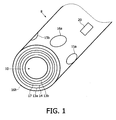
- Fig. 1 schematically shows the tip of a catheter 8.
- a catheter forms a thin hose-like line, through the interior of which for example a guidewire runs or liquids (such as contrast agents) are passed to the catheter tip and can exit through the opening 10.
- a first coil pair comprises the two windings 13a and 13b which surround one another coaxially and during operation are flowed through by currents in opposite directions, the common axis of which windings runs more or less along the axis of the catheter 8.
- the gradient magnetic field generated thereby is shown and described in Figs. 2a and 2b of the document Ax2.
- the position of the field-free point or of the region with a low field strength is selected such that it is located in front of the opening 10 of the catheter 8. Starting from this field-free point, the strength of the magnetic field increases in all three spatial direction as the distance from the field-free point increases.
- various parameters of the arrangement may be changed. If the current intensity of the current flowing through the winding 13a is increased or the current intensity of the current flowing through the winding 13b is reduced, the field-free point is displaced in the direction of the catheter. If, on the other hand, the current intensity of the current flowing through the winding 13a is reduced or the current intensity of the current flowing through the winding 13b is increased, the field-free point is displaced in the opposite direction. Moreover, the position, in particular the starting position, of the field-free point can be affected by changing the diameter of the windings 13a and 13b.
- the spatial size of the region with a higher field strength is sufficiently large.
- the size of the region with a low field strength (shown at reference 301 in Fig. 2b of document Ax2) which determines the spatial resolution of the device depends on the one hand on the strength of the gradient of the gradient magnetic field and on the other hand on the size of the magnetic field required for saturation. For deeper consideration, reference should be made to documents Ax1 and Ax2.
- the field-free point or the region with a low field strength is then displaced along this superposed magnetic field, wherein the size of the displacement increases with the strength of the superposed magnetic fields.
- the superposed magnetic fields have different directions and may be temporally variable.
- a coil 14 generates a magnetic field which runs in the direction of the coil axis of the coil pair 13a, 13b.
- the effect that can be achieved by means of this coil pair can also be achieved by superposing currents of the same direction on the currents of opposite direction in the coil pair 13a, 13b, as a result of which the current decreases in one coil pair and increases in the other coil pair.
- two further coils pairs are provided, comprising the windings 15a, 15b and 16a, 16b.
- the winding 16b is not shown since it is arranged on the underside of the catheter, which is not visible.
- the windings 15a and 15b and the windings 16a and 16b are respectively arranged in an identical manner on the outer surface of the catheter 8 and lie opposite one another.
- the common axis of the coil pair comprising the windings 15a and 15b is perpendicular to the common axis of the coil pair 16a and 16b and the two axes of the coil pairs are in each case perpendicular to the axis of the catheter 8.
- a magnetic field forms between the two windings of a coil pair, the field lines of which magnetic field run on the one hand almost in a straight line through the catheter 8. On the other hand, they run in a curved manner around the catheter 8, wherein they also pass through the field-free point or the region with a low field strength in front of the catheter tip 8 with a component perpendicular to the catheter axis.
- the shape of the windings may also be different in order to optimize the respective curved magnetic field. It is also conceivable for the reasons mentioned above to arrange a soft-magnetic core (not shown) inside the respective coils.
- Fig. 1 shows a further coil 17 which serves to detect signals generated in the zone of action.
- any of the field-generating coil pairs 13 to 16 could also be used for this purpose.
- the coil may be arranged and connected in such a way that it is decoupled from the other coils. If, for example, three receiving coils are fitted on the catheter, their directions of action may lie at an angle of 90° with respect to one another. As a result, signals are detected from all directions around the catheter tip.
- the position of the region with a low magnetic field strength relates to the catheter and no longer to the examination area or to the external components as described in documents Ax1 and Ax1 [sic].
- the position of the region with a low field strength changes within the examination object only when there is a relative movement between catheter and examination object. If, during the time of signal detection, the catheter is stationary with respect to the region of the patient from which the signals are to be detected, the patient can move without this giving rise to movement artifacts. If images of the inner wall of an artery or of a coronary vessel are to be created by means of the catheter, for example, it is expected that even the complex movement of the heart will not lead or will lead only slightly to movement artifacts.
- the coils 14, 15a, 15b, 16a and 16b may be omitted if external coils as described in Ax1 and Ax2 are used to shift the region with a low field strength.
- the catheter 8 it is also possible, by virtue of a different design and arrangement of the magnetic field means, to define the position of the field-free point or of the region with a low field strength so that it is not in front of but rather next to the tip of the catheter 8. This is useful for example when images of regions which are mainly located next to the catheter 8 are to be created.
- the coils or coil arrangements shown in detail in Fig. 1 may then possibly have different shapes or be oriented differently and as a result be arranged differently on the catheter 8. However, their function does not change.
- Fig. 2 shows a catheter 8a which essentially corresponds to the catheter 8 of Fig. 1 .
- the catheter 8a contains all the components of the catheter 8, but these are not shown for the sake of clarity.
- a bar-shaped permanent magnet 25 is fitted on the catheter 8a by a clip 26, one of the poles of said magnet lying at the end of the tip of the catheter 8a.
- the external magnetic field is generated by a coil pair comprising the coils 30 and 31, wherein the coils 30 and 31 are arranged for example around the examination object.
- the permanent magnet 25 is shown here.
- the left end of the permanent magnet 25 in Fig. 3 corresponds to the end of the permanent magnet 25 which faces the tip of the catheter as can be seen in Fig. 2 .
- the catheter 8a has fewer components.
- the region 27 is displaced with respect to the catheter 8a when the catheter 8a or the permanent magnet 25 rotates with respect to the illustrated position in such a way that the field lines of the external magnetic field no longer run parallel to the axis of the permanent magnet 25 or catheter 8a.
- This shift in position can be compensated for example by corresponding activation of the other coils or can be taken into account during signal evaluation.
- Another possibility is to likewise change the direction of the external magnetic field in a manner corresponding to the rotation of the permanent magnet 25. To this end, for example, further external magnetic fields with different directions may be superposed on the external magnetic field.
- the direction in which the catheter 8a or the permanent magnet 25 rotates may for example be determined by three orthogonal receiving coils arranged next to the examination object.
- use may also be made of a ring-shaped permanent magnet which surrounds the tip of the catheter 8a or is embedded therein.
- a permanent magnet use may in general also be made of a coil 26, wherein the course of the field lines shown in Fig. 4 is obtained.
- the catheter 8 shown in Fig. 1 furthermore has a marker 20.
- markers and their function are described in detail for example in document Ax4, so that no further details are given at this point.
- a marker which itself has magnetic properties since it contains magnetic particles for example
- the marker 20 should therefore be arranged at a sufficiently large distance from these components.
- the marker may also be configured such that its magnetic properties differ from the magnetic properties of the magnetic particles located in the surroundings of the catheter 8.
- Such differences may lie for example in the course of the magnetization curve (steepness, hysteresis).
- the signal coming from the marker then has a different spectral composition from the signals coming from the magnetic particles. In the case of a very large hysteresis, the signal coming from the marker may even almost disappear.
- the marker may also be used to calibrate the position of the region with a low field strength with respect to the currents flowing through the coils. This is possible since the geometric position of the marker with respect to the coils is known. If the magnetic field means, in this case the coil pair comprising the two windings 13a and 13b, are not fitted on the catheter, the position of the catheter in the examination area can be determined by means of the marker.
Claims (8)
- Anordnung zum Ermitteln der räumlichen Verteilung von magnetischen Partikeln in einem Untersuchungsbereich, wobei die Anordnung Folgendes umfasst:a) Magnetfeldmittel (13a, 13b, 25, 30, 31) zum Erzeugen eines Magnetfelds mit einem derartigen räumlichen Verlauf der Magnetfeldstärke, dass es in dem Untersuchungsbereich eine erste Teilregion (27) mit einer niedrigen Magnetfeldstärke und eine zweite Teilregion mit einer höheren Magnetfeldstärke gibt,b) Änderungsmittel (14, 15a, 15b, 16a, 16b) zum Ändern der räumlichen Position der beiden Teilregionen in dem Untersuchungsbereich, so dass sich die Magnetisierung der Partikel lokal ändert,c) Detektionsmittel (17) zum Detektieren von Signalen, die von der Magnetisierung in dem Untersuchungsbereich abhängen, die durch die Änderung der räumlichen Position betroffen ist,d) Evaluierungsmittel zum Evaluieren der Signale, um Informationen über die räumliche Verteilung der magnetischen Partikel in dem Untersuchungsbereich zu erlangen, dadurch gekennzeichnet, dass die Anordnung weiterhin Folgendes umfasst:e) ein invasives medizinisches Instrument,und dass:nur eines von den Magnetfeldmitteln, den Änderungsmitteln und den Detektionsmitteln an dem invasiven medizinischen Instrument (8, 8a) angeordnet ist, odernur die Magnetfeldmittel und die Detektionsmittel an dem invasiven medizinischen Instrument (8, 8a) angeordnet sind odernur die Änderungsmittel und die Detektionsmittel an dem invasiven medizinischen Instrument (8, 8a) angeordnet sind odernur die Magnetfeldmittel und die Änderungsmittel an dem invasiven medizinischen Instrument (8, 8a) angeordnet sind oderdie Magnetfeldmittel oder die Änderungsmittel oder die Detektionsmittel oder eine Kombination dieser Mittel teilweise an dem invasiven medizinischen Instrument (8, 8a) angeordnet sind.
- Anordnung nach dem vorhergehenden Anspruch, wobei die an dem medizinischen Instrument angeordneten Magnetfeldmittel eine Spulenanordnung (13a, 13b, 30, 31) und/oder einen Dauermagneten (25) umfassen.
- Anordnung nach einem der vorhergehenden Ansprüche, wobei die an dem medizinischen Instrument angeordneten Magnetfeldmittel mindestens zwei Spulen (13a, 13b) umfassen, die ineinander angeordnet sind, wobei im Betriebszustand Ströme in entgegengesetzten Richtungen durch die Spulen fließen.
- Anordnung nach einem der vorhergehenden Ansprüche, wobei die an dem medizinischen Instrument angeordneten Änderungsmittel eine Spulenanordnung mit einem weichmagnetischen Kern umfassen.
- Anordnung nach Anspruch 1, wobei die an dem medizinischen Instrument angeordneten Detektionsmittel eine Anzahl von Spulen oder Spulenanordnungen umfassen, deren Wirkungsrichtungen in einem Winkel zueinander stehen.
- Anordnung nach einem der vorhergehenden Ansprüche, wobei das invasive medizinische Instrument ein Katheter ist und die daran angeordneten Mittel an oder zumindest in der Nähe der Katheterspitze angeordnet sind.
- Anordnung nach einem der vorhergehenden Ansprüche, umfassend eine Markierung (20) auf dem invasiven medizinischen Instrument.
- Anordnung nach einem der vorhergehenden Ansprüche, wobei die Änderungsmittel derartig konzipiert sind, dass die räumliche Position der beiden Teilregionen in einem Zielbereich so lange und mit einer derartigen Häufigkeit geändert werden kann, dass sich der Zielbereich auf eine gezielte Weise erwärmt.
Priority Applications (1)
| Application Number | Priority Date | Filing Date | Title |
|---|---|---|---|
| EP05850874.8A EP1830703B1 (de) | 2004-12-22 | 2005-12-14 | Anordnung zum bestimmen der räumlichen verteilung von magnetischen teilchen |
Applications Claiming Priority (3)
| Application Number | Priority Date | Filing Date | Title |
|---|---|---|---|
| EP04106838 | 2004-12-22 | ||
| EP05850874.8A EP1830703B1 (de) | 2004-12-22 | 2005-12-14 | Anordnung zum bestimmen der räumlichen verteilung von magnetischen teilchen |
| PCT/IB2005/054248 WO2006067692A2 (en) | 2004-12-22 | 2005-12-14 | Arrangement and method for determining the spatial distribution of magnetic particles |
Publications (2)
| Publication Number | Publication Date |
|---|---|
| EP1830703A2 EP1830703A2 (de) | 2007-09-12 |
| EP1830703B1 true EP1830703B1 (de) | 2016-07-06 |
Family
ID=36602143
Family Applications (1)
| Application Number | Title | Priority Date | Filing Date |
|---|---|---|---|
| EP05850874.8A Not-in-force EP1830703B1 (de) | 2004-12-22 | 2005-12-14 | Anordnung zum bestimmen der räumlichen verteilung von magnetischen teilchen |
Country Status (5)
| Country | Link |
|---|---|
| US (2) | US20090281416A1 (de) |
| EP (1) | EP1830703B1 (de) |
| JP (1) | JP5226319B2 (de) |
| CN (1) | CN101087556A (de) |
| WO (1) | WO2006067692A2 (de) |
Families Citing this family (9)
| Publication number | Priority date | Publication date | Assignee | Title |
|---|---|---|---|---|
| US8212554B2 (en) | 2005-05-11 | 2012-07-03 | The University Of Houston System | Intraluminal magneto sensor system and method of use |
| WO2006122202A1 (en) * | 2005-05-11 | 2006-11-16 | The University Of Houston System | An intraluminal mutlifunctional sensor system and method of use |
| EP2096986B1 (de) | 2006-12-20 | 2018-07-25 | Philips Intellectual Property & Standards GmbH | Anordnung und verfahren zur beeinflussung und/oder erkennung magnetischer partikel in einem wirkungsbereich |
| JP2010512919A (ja) * | 2006-12-20 | 2010-04-30 | コーニンクレッカ フィリップス エレクトロニクス エヌ ヴィ | 検査対象の作用領域内の磁性粒子に影響を与え及び/又はそれらを検出する方法 |
| WO2009104151A2 (en) * | 2008-02-22 | 2009-08-27 | Koninklijke Philips Electronics N.V. | Arrangement and method for influencing and/or detecting magnetic particles in a region of action of an examination object and use of an arrangement |
| EP2406650A1 (de) * | 2009-03-09 | 2012-01-18 | Koninklijke Philips Electronics N.V. | Anordnung und verfahren zur messung eines magnetischen materials in einem wirkungsbereich |
| JP6235601B2 (ja) * | 2012-11-07 | 2017-11-22 | コーニンクレッカ フィリップス エヌ ヴェKoninklijke Philips N.V. | Mpi装置用の磁性素子 |
| EP4085866A3 (de) | 2015-06-04 | 2023-01-18 | Endomagnetics Ltd. | Markermaterialien und -formen zur lokalisierung magnetischer marker |
| EP3378389A1 (de) * | 2017-03-21 | 2018-09-26 | Universität zu Lübeck | Vorrichtung für bildgebende verfahren auf basis des magnetic particle imaging und zugehörige verfahren |
Family Cites Families (20)
| Publication number | Priority date | Publication date | Assignee | Title |
|---|---|---|---|---|
| US5425367A (en) * | 1991-09-04 | 1995-06-20 | Navion Biomedical Corporation | Catheter depth, position and orientation location system |
| US5353795A (en) * | 1992-12-10 | 1994-10-11 | General Electric Company | Tracking system to monitor the position of a device using multiplexed magnetic resonance detection |
| US5728079A (en) * | 1994-09-19 | 1998-03-17 | Cordis Corporation | Catheter which is visible under MRI |
| NL9401517A (nl) * | 1994-09-19 | 1996-05-01 | Cordis Europ | MR-zichtbare catheter. |
| JP3654463B2 (ja) * | 1996-03-29 | 2005-06-02 | 株式会社日立メディコ | 磁気共鳴イメージング装置 |
| DE19736030A1 (de) * | 1997-08-20 | 1999-02-25 | Philips Patentverwaltung | Verfahren zur Navigation eines magnetischen Objektes und MR-Anordung |
| US5964705A (en) * | 1997-08-22 | 1999-10-12 | Image-Guided Drug Delivery System, Inc. | MR-compatible medical devices |
| DE19755782A1 (de) * | 1997-12-16 | 1999-06-17 | Philips Patentverwaltung | MR-Anordnung mit einem medizinischen Instrument und Verfahren zur Positionsbestimmung des medizinischen Instruments |
| US6246896B1 (en) * | 1998-11-24 | 2001-06-12 | General Electric Company | MRI guided ablation system |
| US6470220B1 (en) * | 1999-03-29 | 2002-10-22 | The Regents Of The University Of California | Diagnosis and treatment of cancers using in vivo magnetic domains |
| DE19956595A1 (de) * | 1999-11-25 | 2001-05-31 | Philips Corp Intellectual Pty | MR-Verfahren zur Anregung der Kernmagnetisierung in einem begrenzten räumlichen Bereich |
| DE10113661A1 (de) * | 2001-03-21 | 2002-09-26 | Philips Corp Intellectual Pty | Katheter zur Anwendung in einem Magnetresonanz-Bildgerät |
| US7135978B2 (en) * | 2001-09-14 | 2006-11-14 | Calypso Medical Technologies, Inc. | Miniature resonating marker assembly |
| DE10151778A1 (de) * | 2001-10-19 | 2003-05-08 | Philips Corp Intellectual Pty | Verfahren zur Ermittlung der räumlichen Verteilung magnetischer Partikel |
| DE10238853A1 (de) | 2002-08-24 | 2004-03-04 | Philips Intellectual Property & Standards Gmbh | Verfahren zur lokalen Erwärmung mit magnetischen Partikeln |
| DE10240960A1 (de) | 2002-09-05 | 2004-03-18 | Philips Intellectual Property & Standards Gmbh | Katheter, insbesondere zur Verwendung bei der MR-Bildgebung |
| WO2004023103A2 (en) * | 2002-09-09 | 2004-03-18 | Z-Kat, Inc. | Image guided interventional method and apparatus |
| US20040158144A1 (en) * | 2003-02-03 | 2004-08-12 | Topshooter Medical Imri Inc. | NMR probe particularly useful for intra-luminal imaging |
| WO2004091721A1 (en) * | 2003-04-15 | 2004-10-28 | Philips Intellectual Property & Standards Gmbh | Method and apparatus for influencing magnetic particles |
| CN101087558B (zh) | 2004-12-22 | 2010-10-06 | 皇家飞利浦电子股份有限公司 | 用于通过磁选法确定位置的标示器 |
-
2005
- 2005-12-14 EP EP05850874.8A patent/EP1830703B1/de not_active Not-in-force
- 2005-12-14 JP JP2007547733A patent/JP5226319B2/ja not_active Expired - Fee Related
- 2005-12-14 CN CNA2005800445521A patent/CN101087556A/zh active Pending
- 2005-12-14 WO PCT/IB2005/054248 patent/WO2006067692A2/en active Application Filing
- 2005-12-14 US US11/721,565 patent/US20090281416A1/en not_active Abandoned
-
2010
- 2010-01-29 US US12/696,911 patent/US9480413B2/en not_active Expired - Fee Related
Also Published As
| Publication number | Publication date |
|---|---|
| EP1830703A2 (de) | 2007-09-12 |
| WO2006067692A2 (en) | 2006-06-29 |
| CN101087556A (zh) | 2007-12-12 |
| JP5226319B2 (ja) | 2013-07-03 |
| US20090281416A1 (en) | 2009-11-12 |
| WO2006067692A3 (en) | 2006-09-08 |
| JP2008525082A (ja) | 2008-07-17 |
| US20100249578A1 (en) | 2010-09-30 |
| US9480413B2 (en) | 2016-11-01 |
Similar Documents
| Publication | Publication Date | Title |
|---|---|---|
| US20090299176A1 (en) | Marker for position determination with a magnetic method | |
| US9480413B2 (en) | Arrangement and method for determining the spatial distribution of magnetic particles | |
| EP1615694B1 (de) | Verfahren und anordnung zur beeinflussung magnetischer partikel | |
| KR102287648B1 (ko) | 수술 유도를 위한 자기 마커를 감지하는 시스템 및 방법 | |
| CA2505464C (en) | Catheter tracking with phase information | |
| US7778681B2 (en) | Method of determining the spatial distribution of magnetic particles | |
| Wildermuth et al. | MR-guided percutaneous angioplasty: assessment of tracking safety, catheter handling and functionality | |
| EP1615553B1 (de) | Anordnung zur beeinflussung von magnetischen partikeln | |
| US20100259251A1 (en) | Arangement and method for influencing and/or detecting magnetic particles in a region of action | |
| Gosselin et al. | Characterization of the deflections of a catheter steered using a magnetic resonance imaging system | |
| JP2004215992A (ja) | 体腔内への医療用挿入具の位置及び姿勢検出装置並びにその検出方法 | |
| JP2011509109A (ja) | 磁気共鳴撮像中の対象物の位置及び向きを推定する方法及び装置 | |
| US11850097B2 (en) | Magnetomotive probe system and method of use thereof | |
| US20220257138A1 (en) | Tracking system and marker device to be tracked by the tracking system for a medical procedure | |
| Vogel et al. | iMPI: portable human-sized magnetic particle imaging scanner for real-time endovascular interventions | |
| JP6235601B2 (ja) | Mpi装置用の磁性素子 | |
| JP5970470B2 (ja) | 磁性粒子に影響を及ぼし、かつ/又は前記磁性粒子を検出する装置並びに方法 | |
| Placidi et al. | Review on patents about magnetic localisation systems for in vivo catheterizations | |
| WO2009104151A2 (en) | Arrangement and method for influencing and/or detecting magnetic particles in a region of action of an examination object and use of an arrangement | |
| Kaiser et al. | Interventional MRI: Minimal-invasive Surgery under MR guidance |
Legal Events
| Date | Code | Title | Description |
|---|---|---|---|
| PUAI | Public reference made under article 153(3) epc to a published international application that has entered the european phase |
Free format text: ORIGINAL CODE: 0009012 |
|
| 17P | Request for examination filed |
Effective date: 20070723 |
|
| AK | Designated contracting states |
Kind code of ref document: A2 Designated state(s): AT BE BG CH CY CZ DE DK EE ES FI FR GB GR HU IE IS IT LI LT LU LV MC NL PL PT RO SE SI SK TR |
|
| DAX | Request for extension of the european patent (deleted) | ||
| 17Q | First examination report despatched |
Effective date: 20100301 |
|
| RAP1 | Party data changed (applicant data changed or rights of an application transferred) |
Owner name: PHILIPS INTELLECTUAL PROPERTY & STANDARDS GMBH Owner name: KONINKLIJKE PHILIPS N.V. |
|
| GRAP | Despatch of communication of intention to grant a patent |
Free format text: ORIGINAL CODE: EPIDOSNIGR1 |
|
| INTG | Intention to grant announced |
Effective date: 20160201 |
|
| GRAS | Grant fee paid |
Free format text: ORIGINAL CODE: EPIDOSNIGR3 |
|
| GRAA | (expected) grant |
Free format text: ORIGINAL CODE: 0009210 |
|
| AK | Designated contracting states |
Kind code of ref document: B1 Designated state(s): AT BE BG CH CY CZ DE DK EE ES FI FR GB GR HU IE IS IT LI LT LU LV MC NL PL PT RO SE SI SK TR |
|
| REG | Reference to a national code |
Ref country code: GB Ref legal event code: FG4D |
|
| REG | Reference to a national code |
Ref country code: DE Ref legal event code: R081 Ref document number: 602005049700 Country of ref document: DE Owner name: PHILIPS GMBH, DE Free format text: FORMER OWNERS: PHILIPS INTELLECTUAL PROPERTY & STANDARDS GMBH, 20099 HAMBURG, DE; KONINKLIJKE PHILIPS ELECTRONICS N.V., EINDHOVEN, NL |
|
| REG | Reference to a national code |
Ref country code: AT Ref legal event code: REF Ref document number: 810099 Country of ref document: AT Kind code of ref document: T Effective date: 20160715 Ref country code: CH Ref legal event code: EP |
|
| REG | Reference to a national code |
Ref country code: IE Ref legal event code: FG4D |
|
| REG | Reference to a national code |
Ref country code: DE Ref legal event code: R096 Ref document number: 602005049700 Country of ref document: DE |
|
| REG | Reference to a national code |
Ref country code: NL Ref legal event code: MP Effective date: 20160706 |
|
| REG | Reference to a national code |
Ref country code: LT Ref legal event code: MG4D |
|
| REG | Reference to a national code |
Ref country code: AT Ref legal event code: MK05 Ref document number: 810099 Country of ref document: AT Kind code of ref document: T Effective date: 20160706 |
|
| PG25 | Lapsed in a contracting state [announced via postgrant information from national office to epo] |
Ref country code: NL Free format text: LAPSE BECAUSE OF FAILURE TO SUBMIT A TRANSLATION OF THE DESCRIPTION OR TO PAY THE FEE WITHIN THE PRESCRIBED TIME-LIMIT Effective date: 20160706 Ref country code: LT Free format text: LAPSE BECAUSE OF FAILURE TO SUBMIT A TRANSLATION OF THE DESCRIPTION OR TO PAY THE FEE WITHIN THE PRESCRIBED TIME-LIMIT Effective date: 20160706 Ref country code: FI Free format text: LAPSE BECAUSE OF FAILURE TO SUBMIT A TRANSLATION OF THE DESCRIPTION OR TO PAY THE FEE WITHIN THE PRESCRIBED TIME-LIMIT Effective date: 20160706 Ref country code: IS Free format text: LAPSE BECAUSE OF FAILURE TO SUBMIT A TRANSLATION OF THE DESCRIPTION OR TO PAY THE FEE WITHIN THE PRESCRIBED TIME-LIMIT Effective date: 20161106 Ref country code: IT Free format text: LAPSE BECAUSE OF FAILURE TO SUBMIT A TRANSLATION OF THE DESCRIPTION OR TO PAY THE FEE WITHIN THE PRESCRIBED TIME-LIMIT Effective date: 20160706 |
|
| PG25 | Lapsed in a contracting state [announced via postgrant information from national office to epo] |
Ref country code: SE Free format text: LAPSE BECAUSE OF FAILURE TO SUBMIT A TRANSLATION OF THE DESCRIPTION OR TO PAY THE FEE WITHIN THE PRESCRIBED TIME-LIMIT Effective date: 20160706 Ref country code: PL Free format text: LAPSE BECAUSE OF FAILURE TO SUBMIT A TRANSLATION OF THE DESCRIPTION OR TO PAY THE FEE WITHIN THE PRESCRIBED TIME-LIMIT Effective date: 20160706 Ref country code: ES Free format text: LAPSE BECAUSE OF FAILURE TO SUBMIT A TRANSLATION OF THE DESCRIPTION OR TO PAY THE FEE WITHIN THE PRESCRIBED TIME-LIMIT Effective date: 20160706 Ref country code: LV Free format text: LAPSE BECAUSE OF FAILURE TO SUBMIT A TRANSLATION OF THE DESCRIPTION OR TO PAY THE FEE WITHIN THE PRESCRIBED TIME-LIMIT Effective date: 20160706 Ref country code: BE Free format text: LAPSE BECAUSE OF FAILURE TO SUBMIT A TRANSLATION OF THE DESCRIPTION OR TO PAY THE FEE WITHIN THE PRESCRIBED TIME-LIMIT Effective date: 20160706 Ref country code: GR Free format text: LAPSE BECAUSE OF FAILURE TO SUBMIT A TRANSLATION OF THE DESCRIPTION OR TO PAY THE FEE WITHIN THE PRESCRIBED TIME-LIMIT Effective date: 20161007 Ref country code: PT Free format text: LAPSE BECAUSE OF FAILURE TO SUBMIT A TRANSLATION OF THE DESCRIPTION OR TO PAY THE FEE WITHIN THE PRESCRIBED TIME-LIMIT Effective date: 20161107 Ref country code: AT Free format text: LAPSE BECAUSE OF FAILURE TO SUBMIT A TRANSLATION OF THE DESCRIPTION OR TO PAY THE FEE WITHIN THE PRESCRIBED TIME-LIMIT Effective date: 20160706 |
|
| REG | Reference to a national code |
Ref country code: DE Ref legal event code: R097 Ref document number: 602005049700 Country of ref document: DE |
|
| PG25 | Lapsed in a contracting state [announced via postgrant information from national office to epo] |
Ref country code: EE Free format text: LAPSE BECAUSE OF FAILURE TO SUBMIT A TRANSLATION OF THE DESCRIPTION OR TO PAY THE FEE WITHIN THE PRESCRIBED TIME-LIMIT Effective date: 20160706 Ref country code: RO Free format text: LAPSE BECAUSE OF FAILURE TO SUBMIT A TRANSLATION OF THE DESCRIPTION OR TO PAY THE FEE WITHIN THE PRESCRIBED TIME-LIMIT Effective date: 20160706 |
|
| PLBE | No opposition filed within time limit |
Free format text: ORIGINAL CODE: 0009261 |
|
| STAA | Information on the status of an ep patent application or granted ep patent |
Free format text: STATUS: NO OPPOSITION FILED WITHIN TIME LIMIT |
|
| PG25 | Lapsed in a contracting state [announced via postgrant information from national office to epo] |
Ref country code: DK Free format text: LAPSE BECAUSE OF FAILURE TO SUBMIT A TRANSLATION OF THE DESCRIPTION OR TO PAY THE FEE WITHIN THE PRESCRIBED TIME-LIMIT Effective date: 20160706 Ref country code: BG Free format text: LAPSE BECAUSE OF FAILURE TO SUBMIT A TRANSLATION OF THE DESCRIPTION OR TO PAY THE FEE WITHIN THE PRESCRIBED TIME-LIMIT Effective date: 20161006 Ref country code: CZ Free format text: LAPSE BECAUSE OF FAILURE TO SUBMIT A TRANSLATION OF THE DESCRIPTION OR TO PAY THE FEE WITHIN THE PRESCRIBED TIME-LIMIT Effective date: 20160706 Ref country code: SK Free format text: LAPSE BECAUSE OF FAILURE TO SUBMIT A TRANSLATION OF THE DESCRIPTION OR TO PAY THE FEE WITHIN THE PRESCRIBED TIME-LIMIT Effective date: 20160706 |
|
| 26N | No opposition filed |
Effective date: 20170407 |
|
| REG | Reference to a national code |
Ref country code: CH Ref legal event code: PL |
|
| GBPC | Gb: european patent ceased through non-payment of renewal fee |
Effective date: 20161214 |
|
| PG25 | Lapsed in a contracting state [announced via postgrant information from national office to epo] |
Ref country code: SI Free format text: LAPSE BECAUSE OF FAILURE TO SUBMIT A TRANSLATION OF THE DESCRIPTION OR TO PAY THE FEE WITHIN THE PRESCRIBED TIME-LIMIT Effective date: 20160706 |
|
| PG25 | Lapsed in a contracting state [announced via postgrant information from national office to epo] |
Ref country code: MC Free format text: LAPSE BECAUSE OF FAILURE TO SUBMIT A TRANSLATION OF THE DESCRIPTION OR TO PAY THE FEE WITHIN THE PRESCRIBED TIME-LIMIT Effective date: 20160706 |
|
| REG | Reference to a national code |
Ref country code: FR Ref legal event code: ST Effective date: 20170831 |
|
| REG | Reference to a national code |
Ref country code: IE Ref legal event code: MM4A |
|
| PG25 | Lapsed in a contracting state [announced via postgrant information from national office to epo] |
Ref country code: FR Free format text: LAPSE BECAUSE OF NON-PAYMENT OF DUE FEES Effective date: 20170102 Ref country code: CH Free format text: LAPSE BECAUSE OF NON-PAYMENT OF DUE FEES Effective date: 20161231 Ref country code: LU Free format text: LAPSE BECAUSE OF NON-PAYMENT OF DUE FEES Effective date: 20161214 Ref country code: LI Free format text: LAPSE BECAUSE OF NON-PAYMENT OF DUE FEES Effective date: 20161231 |
|
| PG25 | Lapsed in a contracting state [announced via postgrant information from national office to epo] |
Ref country code: GB Free format text: LAPSE BECAUSE OF NON-PAYMENT OF DUE FEES Effective date: 20161214 Ref country code: IE Free format text: LAPSE BECAUSE OF NON-PAYMENT OF DUE FEES Effective date: 20161214 |
|
| REG | Reference to a national code |
Ref country code: DE Ref legal event code: R082 Ref document number: 602005049700 Country of ref document: DE Representative=s name: MEISSNER BOLTE PATENTANWAELTE RECHTSANWAELTE P, DE Ref country code: DE Ref legal event code: R081 Ref document number: 602005049700 Country of ref document: DE Owner name: PHILIPS GMBH, DE Free format text: FORMER OWNER: PHILIPS INTELLECTUAL PROPERTY & STANDARDS GMBH, 20099 HAMBURG, DE |
|
| PG25 | Lapsed in a contracting state [announced via postgrant information from national office to epo] |
Ref country code: HU Free format text: LAPSE BECAUSE OF FAILURE TO SUBMIT A TRANSLATION OF THE DESCRIPTION OR TO PAY THE FEE WITHIN THE PRESCRIBED TIME-LIMIT; INVALID AB INITIO Effective date: 20051214 Ref country code: CY Free format text: LAPSE BECAUSE OF FAILURE TO SUBMIT A TRANSLATION OF THE DESCRIPTION OR TO PAY THE FEE WITHIN THE PRESCRIBED TIME-LIMIT Effective date: 20160706 |
|
| PG25 | Lapsed in a contracting state [announced via postgrant information from national office to epo] |
Ref country code: TR Free format text: LAPSE BECAUSE OF FAILURE TO SUBMIT A TRANSLATION OF THE DESCRIPTION OR TO PAY THE FEE WITHIN THE PRESCRIBED TIME-LIMIT Effective date: 20160706 |
|
| PGFP | Annual fee paid to national office [announced via postgrant information from national office to epo] |
Ref country code: DE Payment date: 20190228 Year of fee payment: 14 |
|
| REG | Reference to a national code |
Ref country code: DE Ref legal event code: R119 Ref document number: 602005049700 Country of ref document: DE |
|
| PG25 | Lapsed in a contracting state [announced via postgrant information from national office to epo] |
Ref country code: DE Free format text: LAPSE BECAUSE OF NON-PAYMENT OF DUE FEES Effective date: 20200701 |