EP1372248B1 - Verfahren zur Montage eines Spalttopfmotors - Google Patents
Verfahren zur Montage eines Spalttopfmotors Download PDFInfo
- Publication number
- EP1372248B1 EP1372248B1 EP03012467A EP03012467A EP1372248B1 EP 1372248 B1 EP1372248 B1 EP 1372248B1 EP 03012467 A EP03012467 A EP 03012467A EP 03012467 A EP03012467 A EP 03012467A EP 1372248 B1 EP1372248 B1 EP 1372248B1
- Authority
- EP
- European Patent Office
- Prior art keywords
- air gap
- gap sleeve
- fastener
- motor shaft
- motor
- Prior art date
- Legal status (The legal status is an assumption and is not a legal conclusion. Google has not performed a legal analysis and makes no representation as to the accuracy of the status listed.)
- Expired - Lifetime
Links
Images


Classifications
-
- H—ELECTRICITY
- H02—GENERATION; CONVERSION OR DISTRIBUTION OF ELECTRIC POWER
- H02K—DYNAMO-ELECTRIC MACHINES
- H02K15/00—Processes or apparatus specially adapted for manufacturing, assembling, maintaining or repairing of dynamo-electric machines
- H02K15/14—Casings; Enclosures; Supports
-
- F—MECHANICAL ENGINEERING; LIGHTING; HEATING; WEAPONS; BLASTING
- F04—POSITIVE - DISPLACEMENT MACHINES FOR LIQUIDS; PUMPS FOR LIQUIDS OR ELASTIC FLUIDS
- F04D—NON-POSITIVE-DISPLACEMENT PUMPS
- F04D13/00—Pumping installations or systems
- F04D13/02—Units comprising pumps and their driving means
- F04D13/06—Units comprising pumps and their driving means the pump being electrically driven
- F04D13/0606—Canned motor pumps
-
- F—MECHANICAL ENGINEERING; LIGHTING; HEATING; WEAPONS; BLASTING
- F04—POSITIVE - DISPLACEMENT MACHINES FOR LIQUIDS; PUMPS FOR LIQUIDS OR ELASTIC FLUIDS
- F04D—NON-POSITIVE-DISPLACEMENT PUMPS
- F04D29/00—Details, component parts, or accessories
- F04D29/60—Mounting; Assembling; Disassembling
- F04D29/62—Mounting; Assembling; Disassembling of radial or helico-centrifugal pumps
- F04D29/628—Mounting; Assembling; Disassembling of radial or helico-centrifugal pumps especially adapted for liquid pumps
-
- H—ELECTRICITY
- H02—GENERATION; CONVERSION OR DISTRIBUTION OF ELECTRIC POWER
- H02K—DYNAMO-ELECTRIC MACHINES
- H02K5/00—Casings; Enclosures; Supports
- H02K5/04—Casings or enclosures characterised by the shape, form or construction thereof
- H02K5/12—Casings or enclosures characterised by the shape, form or construction thereof specially adapted for operating in liquid or gas
- H02K5/128—Casings or enclosures characterised by the shape, form or construction thereof specially adapted for operating in liquid or gas using air-gap sleeves or air-gap discs
Definitions
- the invention relates to a method for assembling a split pot motor, wherein a split pot is inserted into the motor housing, and a rotatably mounted on a motor shaft rotor is inserted into the containment shell and rotatably supported therein, and wherein the containment shell is closed by a closure having an opening through which the motor shaft is passed.
- the invention further relates to such a preassembled unit for a split pot motor.
- Such split pot motors or canned motors are well known. They are usually used to drive containment pumps or canned pumps, which are used in Ndentsdalerbauweise especially on heating and service water systems.
- the containment shell is first introduced into the motor housing, in particular together with the stator windings arranged thereon, before the motor shaft with the rotatably mounted rotor is subsequently introduced into the containment shell and in one Bearing is stored at the bottom of the split pot. Only in a subsequent assembly step, a bearing carrier is introduced into the opening region of the can, in the bearing of which the free end of the motor shaft is mounted. Through this bearing carrier, which is often formed by a brass turned part, the containment shell is also closed at the same time.
- German patent application DE 39 31 988 A1 shows such a structure of a canned motor, in which the can is closed by a bearing carrier, but for repair the unit rotor, rotor bearings, bearing carrier and canned from the stator is removable as a cartridge.
- the disadvantage here is that a quality control with respect to the rotatability of the rotor shaft during assembly of the unit outside the stator due to the closure of the can with the bearing carrier is not possible because the bearing carrier can not be removed without damaging other components again.
- Object of the present invention is therefore to provide a simple and fast executable assembly method of the type mentioned above, which causes only a small cost with less effort and allows early quality control with respect to the free rotation of the shaft.
- the main advantage lies in the fact that an easily assembled preassembled unit is provided with an enclosed in the containment shell and already mounted therein rotor, which can be easily installed in a short time in the motor housing of the split pot motor.
- the total assembly can be shortened, so that only lower installation costs. It is also possible to check in good time whether the rotor rotates smoothly and correctly balanced. In addition, no separate bearing carrier, in particular no expensive brass turned part is required. It when the closure is positively inserted with an annular region of the outer wall in a region of the inner wall at the opening of the containment shell is particularly advantageous. As a result, an exact positioning of the closure with its motor shaft receiving and / or superimposed opening on the one hand and the containment shell on the other hand guaranteed.
- a particularly fast, simple and inexpensive attachment of the closure can be achieved in that the closure is frictionally secured to the containment shell.
- the closure can be pressed into the opening region of the containment shell.
- the closure can also be firmly bonded to the containment shell. As a result, a particularly stable and non-detachable connection can be created.
- the closure is welded along its circumference either linear or punctiform at several points with the containment shell.
- laser welding in this case particularly small welds can be achieved, which is particularly in smaller engines with thin-walled split pans of great advantage.
- a bearing is arranged in the opening of the closure before closing the containment shell, in which the free end of the motor shaft is mounted. In this way, the rotor is stored simultaneously with the closing of the split pot.
- the closure is formed by a bearing plate, which projects with a collar radially outwardly beyond the containment shell, wherein the open end of the motor housing is closed during insertion of the containment shell through the collar.
- the containment shell may also have a radially outwardly projecting collar through which the motor housing is closed on the end face during introduction of the containment shell. Also in this way, the installation time and costs can be reduced.
- the containment shell is formed by a split tube, which is closed at its end remote from the free end of the motor shaft end by a separate bottom element.
- the containment shell is formed from two interconnected individual elements, whereby a slight adaptation to different sizes and / or designs is possible.
- the bottom element is inserted with an annular area in a form-fitting manner into the containment shell and secured therein in a force-fit and / or materially bonded manner.
- the bottom element can be welded linearly or punctiformly with the containment shell, again providing laser welding technology with particular advantages.
- have a predetermined connection diameter can be fastened to the respective gap tubes of different shape or size, the ends of which are respectively adapted to the corresponding predetermined connection diameter of the closure and the bottom element.
- closure and / or the bottom element is formed by a sheet metal part, which is preferably deep-drawn to its shape.
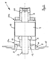
- assembly 1 comprises a containment shell 2, in which a motor shaft 3 is mounted with a rotatably mounted thereon rotor 4 in two running as radial bearings bearings 5.
- the rear bearing 5 is received in a region 6 with a smaller diameter, which is pulled out coaxially in the bottom 7 of the split pot 2.
- a particularly simple and early quality control can be achieved by first checking, after the frictional attachment of the closure on the containment shell, whether the motor shaft is freely rotatable. If the motor shaft should not be freely rotatable, the closure can be relatively easily removed again from the containment shell and offset by a suitable angle offset in another position, followed by a re-examination followed. If the motor shaft is freely rotatable, the closure may optionally be additionally fastened cohesively on the containment shell.
- Such a construction unit for a split pot motor comprises a split pot with a rotatably mounted therein and mounted on a motor shaft rotor, wherein the gap pot outside the split pot motor is closed by a closure having an opening through which the motor shaft is passed.
- the closure is formed by a bearing plate having an at least substantially radially outwardly beyond the gap pot projecting collar through which the housing of the gap pot motor is closed at the front.
- the containment shell is formed by a split tube, which is closed at its end remote from the free end of the motor shaft end by a separate bottom element.
- closure and the bottom element which are advantageously each formed as a standard standard parts, respectively
- a closure 9 At the bottom 7 facing away from the open side 8 of the containment shell 2 is inventively closed by a closure 9, so that the rotor 4 is quasi caught in the containment shell 2 before the containment shell 2 is inserted as a preassembled unit 1 in the housing 10 of the split pot motor 11 ,
- the motor shaft 3 projects out of the assembly 1 through a central opening 12 in the closure 9.
- the shutter 9 is designed as a deep-drawn sheet metal part. It forms a bearing plate which receives the front bearing 5 in a central guide bushing 13. With a cylindrical joining region 14 of the closure 9 is positively and non-positively pressed into the inner wall of the split pot 2. Although this already sufficient strength is given can additionally be made a welded joint.
- a collar 15 projects disc-shaped essentially radially outward over the containment shell 2, through which the open end face of the motor housing 10 is closed during introduction of the containment shell 2. At the same time, the collar 15 with its side facing away from the motor 11 limits the impeller space 16 of the split-pot pump 17 driven by the electric motor 11.
- suitable support means 18 may be provided in the motor housing 10, which press axially on the bottom 7 of the containment shell 2 in order to allow the use even at higher pressures.
- a split tube 19 is closed at its bottom by a separate bottom element 20 which is positively and non-positively attached to the can 19 and additionally welded thereto.
- the bottom member 20 can be made relatively stable, so that no support means are required even at higher delivery pressures. Also, the bottom member 20 receives the rear bearing 5.
- the split pot formed from the can 19 and the bottom element 20 is closed by the closure 9, before the containment shell is introduced as a preassembled unit 1 in the housing 10 of the split pot motor 11.
- the split tube 19 may be graduated in different degrees cone-shaped in a front and rear portion 23 a, 23 b to attach different diameter of the can 19 for different diameters of different rotors 4 via constant connection diameter on the closure 9 and on the bottom element 20 can ,
Landscapes
- Engineering & Computer Science (AREA)
- Mechanical Engineering (AREA)
- General Engineering & Computer Science (AREA)
- Power Engineering (AREA)
- Manufacturing & Machinery (AREA)
- Manufacture Of Motors, Generators (AREA)
Description
- Die Erfindung betrifft ein Verfahren zur Montage eines Spalttopfmotors, wobei ein Spalttopf in das Motorgehäuse eingebracht wird, und ein auf einer Motorwelle befestigter Rotor in den Spalttopf eingebracht und darin drehbar gelagert wird, und wobei der Spalttopf durch einen Verschluß verschlossen wird, welcher eine Öffnung aufweist, durch die die Motorwelle hindurchgeführt wird. Die Erfindung betrifft ferner eine derart vormontierte Baueinheit für einen Spalttopfmotor.
- Derartige Spalttopfmotoren oder Spaltrohrmotoren sind allgemein bekannt. Sie werden üblicherweise zum Antrieb von Spalttopfpumpen bzw. Spaltrohrpumpen verwendet, die in Naßläuferbauweise vor allem an Heizungs- und Brauchwasseranlagen eingesetzt werden.
- Bei der Montage dieser bekannten Spalttopfmotoren wird zunächst der Spalttopf insbesondere zusammen mit den darauf angeordneten Statorwicklungen in das Motorgehäuse eingebracht, bevor anschließend die Motorwelle mit dem drehfest darauf befestigten Rotor in den Spalttopf eingebracht und in einem Lager am Boden des Spalttopfes gelagert wird. Erst in einem nachfolgenden Montageschritt wird ein Lagerträger in den Öffnungsbereich des Spalttopfes eingebracht, in dessen Lager das freie Ende der Motorwelle gelagert wird. Durch diesen Lagerträger, der oftmals durch ein Messingdrehteil gebildet ist, wird der Spalttopf gleichzeitig auch geschlossen.
- Das stellt einen erheblichen Arbeitsaufwand dar und bedeutet ein relativ langdauerndes und mit relativ hohen Kosten verbundenes Montageverfahren.
- Die deutsche Offenlegungsschrift
DE 39 31 988 A1 zeigt einen derartigen Aufbau eines Spaltrohrmotors, bei dem das Spaltrohr durch einen Lagerträger verschlossen ist, wobei jedoch zu Reparaturzwecken die Baueinheit Rotor, Rotorlager, Lagerträger und Spaltrohr aus dem Stator als Kartusche herausnehmbar ist. Nachteilig ist hierbei, dass eine Qualitätskontrolle bezüglich der Drehbarkeit der Rotorwelle bei der Montage der Baueinheit außerhalb des Stators aufgrund des Verschlusses des Spaltrohres mit dem Lagerträger nicht möglich ist, da der Lagerträger nicht ohne Beschädigung anderer Bauteile wieder entfernt werden kann. - Aufgabe der vorliegenden Erfindung ist es daher, ein einfach und schnell ausführbares Montageverfahren der eingangs genannten Art zu schaffen, das bei einem geringeren Arbeitsaufwand nur geringe Kosten verursacht und eine frühzeitige Qualitätskontrolle bezüglich der freien Drehbarkeit der Welle ermöglicht.
- Diese Aufgabe wird erfindungsgemäß durch ein Verfahren nach Anspruch 1 gelöst. Vorteilhafte Ausgestaltungen und Weiterbildungen der Erfindung ergeben sich aus den abhängigen Ansprüchen.
- Wesentlich bei der erfindungsgemäßen Lösung ist es, daß zunächst der auf der Motorwelle befestigte Rotor in den Spalttopf eingebracht und darin drehbar gelagert wird, und daß danach der Spalttopf durch den Verschluß verschlossen wird, und daß erst danach der Spalttopf mit dem darin eingeschlossenen Rotor in das Motorgehäuse eingebracht wird.
- Der Hauptvorteil liegt dabei darin, daß eine leicht herzustellende vormontierte Baueinheit mit einem in dem Spalttopf eingeschlossenen und bereits darin gelagerten Rotor geschaffen wird, die leicht und in kurzer Zeit weiter in das Motorgehäuse des Spalttopfmotors eingebaut werden kann.
- Hierdurch kann die Montage insgesamt verkürzt werden, so daß nur geringere Montagekosten anfallen. Auch kann frühzeitig überprüft werden, ob der Rotor leichtgängig und korrekt ausgewuchteten umläuft. Außerdem ist kein separater Lagerträger, insbesondere kein teures Messingdrehteil mehr erforderlich. Besonders vorteilhaft ist es, wenn der Verschluß mit einem ringförmigen Bereich der Außenwandung formschlüssig in einen Bereich der Innenwandung an der Öffnung des Spalttopfs eingesetzt wird. Hierdurch ist eine exakte Positionierung des Verschlusses mit seiner die Motorwelle aufnehmenden und/oder lagernden Öffnung einerseits und dem Spalttopf andererseits gewährleistet.
- Eine besonders schnelle, einfache und kostengünstige Befestigung des Verschlusses kann dadurch erreicht werden, daß der Verschluß kraftschlüssig an dem Spalttopf befestigt wird. Vorzugsweise kann der Verschluß in den Öffnungsbereich des Spalttopfs eingepreßt werden.
- Alternativ oder zusätzlich kann der Verschluß auch stoffschlüssig an dem Spalttopf befestigt werden. Hierdurch kann eine besonders stabile und nicht lösbare Verbindung geschaffen werden.
- Vorzugsweise wird hierzu vorgeschlagen, daß der Verschluß entlang seines Umfangs entweder linienförmig oder an mehreren Stellen punktförmig mit dem Spalttopf verschweißt wird. Durch Laser-Schweißen können hierbei besonders kleine Schweißnähte erreicht werden, was insbesondere bei kleineren Motoren mit dünnwandigen Spalttöpfen von großem Vorteil ist.
- Besonders vorteilhaft ist es ferner, wenn in der Öffnung des Verschlusses vor dem Verschließen des Spalttopfes ein Lager angeordnet wird, in welchem das freie Ende der Motorwelle gelagert wird. Auf diese Weise wird der Rotor gleichzeitig mit dem Verschließen des Spalttopfes gelagert.
- Gemäß einer besonders bevorzugten Ausführungsform der Erfindung wird der Verschluß durch einen Lagerschild gebildet, der mit einem Kragen radial nach außen über den Spalttopf übersteht, wobei die offene Stirnseite des Motorgehäuses beim Einbringen des Spalttopfes durch den Kragen verschlossen wird. Hierdurch können die Gesamt-Montagedauer weiter verkürzt und die Kosten zusätzlich gesenkt werden.
Bei einer Ausführungsvariante der Erfindung kann auch hat der Spalttopf einen radial nach außen vorstehenden Kragen haben, durch den das Motorgehäuse beim Einbringen des Spalttopfes stirnseitig verschlossen wird. Auch auf diese Weise können die Montagedauer und die Kosten reduziert werden. - Gemäß einer weiteren besonders bevorzugten Ausführungsform der Erfindung wird der Spalttopf durch ein Spaltrohr gebildet, welches an seinem dem freien Ende der Motorwelle abgewandten Ende durch ein separates Bodenelement verschlossen wird. Der Spalttopf wird dabei aus zwei miteinander verbundenen Einzelelementen gebildet, wodurch eine leichte Anpassung an verschiedene Baugrößen und/oder Bauformen möglich ist.
- Ähnlich wie bei dem Verschluß ist es auch hier von Vorteil, wenn das Bodenelement mit einem ringförmigen Bereich formschlüssig in den Spalttopf eingesetzt und darin kraftschlüssig und/oder stoffschlüssig befestigt wird.
- Vorzugsweise kann das Bodenelement linienförmig oder punktförmig mit dem Spalttopf verschweißt werden, wobei wiederum die Laser-Schweißtechnik besondere Vorteile bietet. einen vorgegebenen Anschlußdurchmesser aufweise, an den jeweils Spaltrohre unterschiedlicher Form bzw. Größe befestigbar sind, deren Enden jeweils an die entsprechenden vorgegebenen Anschlußdurchmesser des Verschlusses und des Bodenelementes angepaßt sind.
- Besonders vorteilhaft und kostengünstig ist es ferner, wenn der Verschluß und/oder das Bodenelement durch ein Blechteil gebildet ist, welches zu seiner Formgebung vorzugsweise tiefgezogen ist.
- Weitere Vorteile und Merkmale der Erfindung ergeben sich aus der nachfolgenden Beschreibung und den in den Zeichnungen dargestellten Ausführungsbeispielen.
Es zeigen: - Figur 1:
- Schematische Darstellung einer ersten Ausführungsart der Baueinheit gemäß dem vorangehend beschriebenen Verfahren;
- Figur 2:
- Schematische Darstellung einer zweiten Ausführungsart der Baueinheit gemäß dem vorangehend beschriebenen Verfahren;
- Figur 3:
- Baueinheit gemäß
Figur 2 mit weiteren Anbauteilen; - Figur 4:
- Baueinheit aus
Figur 3 , eingebaut in einen Motor einer Spalttopfpumpe. - Die in
Figur 1 dargestellte Baueinheit 1 umfaßt einen Spalttopf 2, in dem eine Motorwelle 3 mit einem drehfest darauf befestigten Rotor 4 in zwei als Radial-Gleitlager ausgeführten Lagern 5 gelagert ist. Das hintere Lager 5 ist dabei in einem Bereich 6 mit geringerem Durchmesser aufgenommen, der im Boden 7 des Spalttopfs 2 koaxial herausgezogen ist. - Eine besonders einfache und frühzeitige Qualitätskontrolle kann dadurch erreicht werden, daß nach der kraftschlüssigen Befestigung des Verschlusses am Spalttopf zunächst geprüft wird, ob die Motorwelle frei drehbar ist. Falls die Motorwelle nicht frei drehbar sein sollte, so kann der Verschluß relativ einfach wieder von dem Spalttopf entfernt und um einen geeigneten Winkel versetzt in einer anderen Position erneut aufgebracht werden, woran sich eine erneute Überprüfung anschließt. Wenn die Motorwelle frei drehbar ist kann der Verschluß gegebenenfalls zusätzlich stoffschlüssig am Spalttopf befestigt werden.
- Ein Beispiel einer gemäß dem vorangehend beschriebenen Verfahren vormontierten Baueinheit für einen Spalttopfmotor wird gegeben. Eine derartige Baueinheit für einen Spalttopfmotor umfaßt einen Spalttopf mit einem drehbar darin gelagerten und auf einer Motorwelle befestigten Rotor, wobei der Spalttopf außerhalb des Spalttopfmotors durch einen Verschluß verschlossen ist, der eine Öffnung aufweist, durch die die Motorwelle hindurchgeführt ist.
- Besonders vorteilhaft ist es dabei, wenn der Verschluß durch einen Lagerschild gebildet ist, der einen zumindest im wesentlichen radial nach außen über den Spalttopf überstehenden Kragen aufweist, durch den das Gehäuse des Spalttopfmotors stirnseitig verschließbar ist.
- Vorzugsweise ist der Spalttopf durch ein Spaltrohr gebildet, welches an seinem dem freien Ende der Motorwelle abgewandten Ende durch ein separates Bodenelement verschlossen ist.
- Eine besonders große Flexibilität bezüglich unterschiedlicher Formen und/oder Größen, insbesondere bezüglich unterschiedlicher Durchmesser und/oder unterschiedlicher Längen des Rotors kann mit relativ geringerem Aufwand dadurch erreicht werden, daß der Verschluß und das Bodenelement, die vorteilhafterweise jeweils als einheitliche Standardteile ausgebildet sind, jeweils An der dem Boden 7 abgewandten offenen Seite 8 wird der Spalttopf 2 erfindungsgemäß durch einen Verschluß 9 verschlossen, so daß der Rotor 4 quasi in dem Spalttopf 2 gefangen ist, bevor der Spalttopf 2 als vormontierte Baueinheit 1 in das Gehäuse 10 des Spalttopfmotors 11 eingebracht wird. Die Motorwelle 3 ragt dabei durch eine zentrale Öffnung 12 im Verschluß 9 aus der Baueinheit 1 heraus.
- Der Verschluß 9 ist als tiefgezogenes Blechteil ausgeführt. Er bildet einen Lagerschild, der in einer zentralen Führungsbuchse 13 das vordere Lager 5 aufnimmt. Mit einem zylindrischen Fügebereich 14 ist der Verschluß 9 form- und kraftschlüssig in die Innenwandung des Spalttopfs 2 hineingepreßt. Obwohl hierdurch schon eine ausreichende Festigkeit gegeben ist kann zusätzlich noch eine Schweißverbindung vorgenommen werden.
Ein Kragen 15 steht scheibenförmig im wesentlichen radial nach außen über den Spalttopf 2 über, durch den die offene Stirnseite des Motorgehäuses 10 beim Einbringen des Spalttopfes 2 verschlossen wird. Gleichzeitig begrenzt der Kragen 15 mit seiner dem Motor 11 abgewandten Seite den Laufradraum 16 der von dem Elektromotor 11 angetriebenen Spalttopfpumpe 17. - Je nach Anwendung der Pumpe 17 können im Motorgehäuse 10 geeignete Abstützmittel 18 vorgesehen sein, die axial auf den Boden 7 des Spalttopfs 2 drücken, um den Einsatz auch bei höheren Drücken zu ermöglichen.
- Während bei der Alternative gemäß
Figur 1 der Spalttopf 2 einstückig ausgebildet ist, ist er bei der Alternative gemäßFigur 2 zweistückig ausgeführt. Ein Spaltrohr 19 ist an seinem Boden durch ein separates Bodenelement 20 verschlossen, welches formschlüssig und kraftschlüssig an dem Spaltrohr 19 befestigt und zusätzlich noch daran verschweißt ist. Das Bodenelement 20 kann dabei relativ stabil ausgeführt werden, so daß auch bei höheren Förderdrücken keine Abstützmittel erforderlich sind. Auch nimmt das Bodenelement 20 das hintere Lager 5 auf. - Auch bei der Alternative gemäß
Figur 2 wird der aus Spaltrohr 19 und Bodenelement 20 gebildete Spalttopf durch den Verschluß 9 verschlossen, bevor der Spalttopf als vormontierte Baueinheit 1 in das Gehäuse 10 des Spalttopfmotors 11 eingebracht wird. - Vor dem Einbringen der Baueinheit 1 in das Motorgehäuse 10 können noch weitere Bauelemente angebracht werden, beispielsweise ein Pumpenlaufrad 21 oder eine Löseschraube 22, nach deren Entfernung die Motorwelle 3 stirnseitig zugänglich ist und nötigenfalls von außen manipuliert werden kann (
Figur 3 ). - Bei einem Vergleich der
Figuren 2 und3 ist festzustellen, daß das Spaltrohr 19 in einem vorderen und hinteren Bereich 23a, 23b unterschiedlich stark konusförmig abgestuft sein kann, um unterschiedliche Durchmesser des Spaltrohres 19 für verschiedenen Durchmesser unterschiedlicher Rotoren 4 über konstante Anschlußdurchmesser an dem Verschluß 9 und an dem Bodenelement 20 befestigen zu können. - Wesentlich ist jedoch in jedem Falle, daß der Rotor 4 mit der Motorwelle 3 in den Spalttopf 2 bzw. 19, 20 eingebracht und darin durch den Verschluß 9 eingeschlossen wird, bevor diese vormontierte Baueinheit 1 in das Motorgehäuse 10 eingebracht wird.
Claims (9)
- Verfahren zur Montage eines Spalttopfmotors (11), wobei ein Spalttopf (2) in das Motorgehäuse (10) eingebracht wird, und ein auf einer Motorwelle (3) befestigter Rotor (4) in den Spalttopf (2) eingebracht und darin drehbar gelagert wird, und wobei der Spalttopf (2) durch einen Verschluss (9) verschlossen wird, welcher eine Öffnung (12) aufweist, durch die die Motorwelle (3) hindurchgeführt wird,
dadurch gekennzeichnet,
dass zunächst der auf der Motorwelle (3) befestigte Rotor (4) in den Spalttopf (2) eingebracht und darin drehbar gelagert wird,
und dass danach der Spalttopf (2) durch den Verschluß (9) verschlossen wird, und dass erst danach der Spalttopf (2) mit dem darin eingeschlossenen Rotor (4) in das Motorgehäuse (10) eingebracht wird, wobei der Verschluss (9) kraftschlüssig an dem Spalttopf (2) befestigt, insbesondere darin eingepresst wird
und dass nach der kraftschlüssigen Befestigung des Verschlusses (9) am Spalttopf (2) zunächst geprüft wird, ob die Motorwelle (3) frei drehbar ist,
und dass der Verschluss (9) wieder von dem Spalttopf (2) entfernt und in einer um einen Winkel verdrehten Position erneut aufgebracht wird, falls die Motorwelle (3) nicht frei drehbar ist,
und dass der Verschluss (9) gegebenenfalls stoffschlüssig am Spalttopf (2) befestigt wird, wenn die Motorwelle (3) frei drehbar ist. - Verfahren nach Anspruch 1 dadurch gekennzeichnet, dass der Verschluss (9) stoffschlüssig an dem Spalttopf (2) befestigt wird.
- Verfahren nach Anspruch 2, dadurch gekennzeichnet, dass der Verschluss (9) linienförmig oder an mehreren Stellen punktförmig mit dem Spalttopf (2) verschweißt, insbesondere laserverschweißt wird.
- Verfahren nach einem der vorherigen Ansprüche, dadurch gekennzeichnet, dass in der Öffnung (12) des Verschlusses (9) vor dem Verschließen des Spalttopfes (2) ein Lager (5) angeordnet wird, in welchem das freie Ende der Motorwelle (3) gelagert wird.
- Verfahren nach einem der vorherigen Ansprüche, dadurch gekennzeichnet, dass der Verschluss (9) durch einen Lagerschild gebildet wird, der mit einem Kragen (15) radial nach außen über den Spalttopf (2) übersteht, wobei das Motorgehäuse (10) stirnseitig durch den Kragen (15) verschlossen wird.
- Verfahren nach einem der Ansprüche 1 bis 4, dadurch gekennzeichnet, dass der Spalttopf (2) einen radial nach außen vorstehenden Kragen aufweist, durch den das Motorgehäuse (10) beim Einbringen des Spalttopfes (2) stirnseitig verschlossen wird.
- Verfahren nach einem der vorherigen Ansprüche, dadurch gekennzeichnet, dass der Spalttopf (2) durch ein Spaltrohr (19) gebildet wird, welches an seinem dem freien Ende der Motorwelle (3) abgewandten Ende durch ein Bodenelement (20) verschlossen wird.
- Verfahren nach Anspruch 7, dadurch gekennzeichnet, dass das Bodenelement (20) mit einem ringförmigen Bereich formschlüssig in das Spaltrohr (19) eingesetzt wird und darin kraftschlüssig und/oder stoffschlüssig befestigt wird.
- Verfahren nach Anspruch 7 oder 8, dadurch gekennzeichnet, dass das Bodenelement (20) linienförmig oder an mehreren Stellen punktförmig mit dem Spaltrohr (19) verschweißt, insbesondere laserverschweißt wird.
Applications Claiming Priority (2)
| Application Number | Priority Date | Filing Date | Title |
|---|---|---|---|
| DE10226145 | 2002-06-13 | ||
| DE10226145A DE10226145A1 (de) | 2002-06-13 | 2002-06-13 | Verfahren zur Montage eines Spalttopfmotors |
Publications (3)
| Publication Number | Publication Date |
|---|---|
| EP1372248A2 EP1372248A2 (de) | 2003-12-17 |
| EP1372248A3 EP1372248A3 (de) | 2005-07-20 |
| EP1372248B1 true EP1372248B1 (de) | 2008-10-22 |
Family
ID=29557788
Family Applications (1)
| Application Number | Title | Priority Date | Filing Date |
|---|---|---|---|
| EP03012467A Expired - Lifetime EP1372248B1 (de) | 2002-06-13 | 2003-05-31 | Verfahren zur Montage eines Spalttopfmotors |
Country Status (2)
| Country | Link |
|---|---|
| EP (1) | EP1372248B1 (de) |
| DE (2) | DE10226145A1 (de) |
Families Citing this family (8)
| Publication number | Priority date | Publication date | Assignee | Title |
|---|---|---|---|---|
| DE102006021247B4 (de) * | 2006-04-28 | 2012-02-02 | Bühler Motor GmbH | Elektromotor |
| DE102006021246A1 (de) * | 2006-04-28 | 2007-10-31 | Bühler Motor GmbH | Elektromotor |
| DE102006021242B4 (de) | 2006-04-28 | 2012-06-21 | Bühler Motor GmbH | Elektromotor |
| CN102788026B (zh) * | 2011-05-16 | 2015-07-08 | 梁嘉麟 | 电机定子绕组可拆卸式全密封型液泵装置运行时能够防止泄漏内部液体分子的密封方法 |
| CN103580317B (zh) * | 2012-08-10 | 2017-08-08 | 浙江三花制冷集团有限公司 | 一种屏蔽泵永磁电机 |
| IT201800000658A1 (it) * | 2018-01-10 | 2019-07-10 | Dab Pumps Spa | Assemblato di pompa con manicotto di traferro perfezionato e accoppiamento tra rotore e manicotto di traferro perfezionato |
| DE102018115952A1 (de) * | 2018-07-02 | 2020-01-02 | Ebm-Papst St. Georgen Gmbh & Co. Kg | Motoranordnung mit einem Spalttopf |
| CN115111185B (zh) * | 2022-05-28 | 2025-09-12 | 上海鸣志电器股份有限公司 | 一种轴承固定结构及具有该结构的泵机组 |
Citations (2)
| Publication number | Priority date | Publication date | Assignee | Title |
|---|---|---|---|---|
| DE19525704C1 (de) * | 1995-07-14 | 1996-07-25 | Grundfos As | Gekapselter Rotor |
| EP1211783A2 (de) * | 2000-11-30 | 2002-06-05 | Grundfos A/S | Nasslaufender elektrischer Antriebsmotor für insbesondere eine Heizungsumwälzpumpe |
Family Cites Families (9)
| Publication number | Priority date | Publication date | Assignee | Title |
|---|---|---|---|---|
| FR1531555A (fr) * | 1967-05-23 | 1968-07-05 | Drouard Moteurs | Moteur électrique à chemise d'entrefer perfectionné |
| DE2751516A1 (de) * | 1977-11-18 | 1979-05-23 | Hanning Elektro Werke | Pumpe, insbesondere heizungsumwaelzpumpe |
| FR2650923B1 (fr) * | 1989-08-11 | 1995-05-24 | Salmson Pompes | Stator de moteur electrique et moteur electrique comportant un tel stator |
| DE3931988A1 (de) * | 1989-09-26 | 1991-04-04 | Oplaender Wilo Werk Gmbh | Spaltrohrmotor |
| DE4129590C3 (de) * | 1991-09-06 | 2002-03-07 | Progress Werk Oberkirch Ag | Verfahren zum Herstellen eines Spalttopfes für einen Spaltrohrmotor sowie Spalttopf für einen derartigen Spaltrohrmotor |
| DE4441378A1 (de) * | 1994-11-21 | 1996-05-30 | Wilo Gmbh | Spalttopf einer Kreiselpumpe |
| DE19509134A1 (de) * | 1995-03-14 | 1996-09-19 | Wilo Gmbh | Statorbefestigung für einen Spaltrohrmotor |
| DE19705974A1 (de) * | 1997-02-17 | 1998-08-20 | Wilo Gmbh | Elektromotor für eine Pumpe oder einen Lüfter |
| DE10059458A1 (de) * | 2000-11-30 | 2002-06-13 | Grundfos As | Elektrischer Antriebsmotor für eine Kreiselpumpe für insbesondere Heizungsanlagen |
-
2002
- 2002-06-13 DE DE10226145A patent/DE10226145A1/de not_active Withdrawn
-
2003
- 2003-05-31 EP EP03012467A patent/EP1372248B1/de not_active Expired - Lifetime
- 2003-05-31 DE DE50310662T patent/DE50310662D1/de not_active Expired - Lifetime
Patent Citations (2)
| Publication number | Priority date | Publication date | Assignee | Title |
|---|---|---|---|---|
| DE19525704C1 (de) * | 1995-07-14 | 1996-07-25 | Grundfos As | Gekapselter Rotor |
| EP1211783A2 (de) * | 2000-11-30 | 2002-06-05 | Grundfos A/S | Nasslaufender elektrischer Antriebsmotor für insbesondere eine Heizungsumwälzpumpe |
Also Published As
| Publication number | Publication date |
|---|---|
| EP1372248A2 (de) | 2003-12-17 |
| DE50310662D1 (de) | 2008-12-04 |
| EP1372248A3 (de) | 2005-07-20 |
| DE10226145A1 (de) | 2004-03-11 |
Similar Documents
| Publication | Publication Date | Title |
|---|---|---|
| DE3614748C2 (de) | Elektromotor, insbesondere kollektorloser Gleichstrommotor, mit einem Außenrotor | |
| EP1745540B1 (de) | Elektromotor und getriebe-antriebseinheit für stellantriebe im kraftfahrzeug | |
| EP0160971A2 (de) | Lagerung für Antriebsmotor eines kleinstventilators | |
| DE102010047008A1 (de) | Verbindungsstruktur zur mechanischen Verbindung eines ersten Gehäuses mit einem zweiten Gehäuse | |
| EP3390999A1 (de) | Statorhalter, statorbaugruppe, verfahren zum zusammenbau einer statorbaugruppe, drehmomentsensorvorrichtung mit einer statorbaugruppe und einem statorhalter und kraftfahrzeug mit einer drehmomentsensorvorrichtung | |
| EP2236248A2 (de) | Vorrichtung zur Demontage eines Radlagergehäuses | |
| DE102008054330A1 (de) | Zweiteiliges Motorgehäuse mit Bajonett-Verbindung | |
| DE102014205582B4 (de) | Antriebseinrichtung | |
| DE102019124839B4 (de) | Montagewerkzeug zum Montieren eines Rotors, Verfahren zum Montieren eines Rotors und Antriebsvorrichtung | |
| DE4039453C2 (de) | Elektrischer Kleinmotor, insbesondere zum Antrieb einer Scheibenwischanlage an einem Kraftfahrzeug | |
| EP1372248A2 (de) | Verfahren zur Montage eines Spalttopfmotors | |
| DE2902723A1 (de) | Pumpe, insbesondere fluegelzellenpumpe, mit einer gleitlagerung | |
| DE2162268C3 (de) | Gehäuse für ein Motor-Verdichteraggregat | |
| DE2448699A1 (de) | Verfahren zur herstellung elektrischer maschinen | |
| DE19521425A1 (de) | Handwerkzeugmaschine mit Elektromotor, sowie deren Elektromotor | |
| DE102009028133A1 (de) | Lagereinrichtung | |
| DE202008017587U1 (de) | Rotor | |
| DE102010064298A1 (de) | Einrichtung zur Lagerung einer Welle in einem Gehäuse und Aggregat mit einer erfindungsgemäßen Einrichtung | |
| DE19602173A1 (de) | Elektromotorgehäuse | |
| DE102015106614A1 (de) | Pumpenvorrichtung | |
| EP2199028B1 (de) | Elektrohandwerkzeug, insbesondere Bohr- und/oder Schlaghammer | |
| EP1041700A2 (de) | Motorangetriebenes Aggregat | |
| DE112008000928T5 (de) | Verfahren zur Montage eines Kältemaschinenkompressors | |
| DE10035254B4 (de) | Verschlußelement für das Gehäuse des Motors eines Kraftfahrzeuganlassers und Anlasser mit einem solchen Verschlußelement | |
| DE102013114112A1 (de) | Außenläufermotor, Lüftervorrichtung sowie Montage- und Demontageverfahren |
Legal Events
| Date | Code | Title | Description |
|---|---|---|---|
| PUAI | Public reference made under article 153(3) epc to a published international application that has entered the european phase |
Free format text: ORIGINAL CODE: 0009012 |
|
| AK | Designated contracting states |
Kind code of ref document: A2 Designated state(s): AT BE BG CH CY CZ DE DK EE ES FI FR GB GR HU IE IT LI LU MC NL PT RO SE SI SK TR |
|
| AX | Request for extension of the european patent |
Extension state: AL LT LV MK |
|
| PUAL | Search report despatched |
Free format text: ORIGINAL CODE: 0009013 |
|
| AK | Designated contracting states |
Kind code of ref document: A3 Designated state(s): AT BE BG CH CY CZ DE DK EE ES FI FR GB GR HU IE IT LI LU MC NL PT RO SE SI SK TR |
|
| AX | Request for extension of the european patent |
Extension state: AL LT LV MK |
|
| 17P | Request for examination filed |
Effective date: 20050808 |
|
| AKX | Designation fees paid |
Designated state(s): DE FR GB IT |
|
| 17Q | First examination report despatched |
Effective date: 20060113 |
|
| GRAP | Despatch of communication of intention to grant a patent |
Free format text: ORIGINAL CODE: EPIDOSNIGR1 |
|
| GRAS | Grant fee paid |
Free format text: ORIGINAL CODE: EPIDOSNIGR3 |
|
| GRAA | (expected) grant |
Free format text: ORIGINAL CODE: 0009210 |
|
| AK | Designated contracting states |
Kind code of ref document: B1 Designated state(s): DE FR GB IT |
|
| REG | Reference to a national code |
Ref country code: GB Ref legal event code: FG4D Free format text: NOT ENGLISH |
|
| REF | Corresponds to: |
Ref document number: 50310662 Country of ref document: DE Date of ref document: 20081204 Kind code of ref document: P |
|
| PLBE | No opposition filed within time limit |
Free format text: ORIGINAL CODE: 0009261 |
|
| STAA | Information on the status of an ep patent application or granted ep patent |
Free format text: STATUS: NO OPPOSITION FILED WITHIN TIME LIMIT |
|
| 26N | No opposition filed |
Effective date: 20090723 |
|
| PGFP | Annual fee paid to national office [announced via postgrant information from national office to epo] |
Ref country code: GB Payment date: 20140528 Year of fee payment: 12 |
|
| GBPC | Gb: european patent ceased through non-payment of renewal fee |
Effective date: 20150531 |
|
| REG | Reference to a national code |
Ref country code: FR Ref legal event code: PLFP Year of fee payment: 14 |
|
| PG25 | Lapsed in a contracting state [announced via postgrant information from national office to epo] |
Ref country code: GB Free format text: LAPSE BECAUSE OF NON-PAYMENT OF DUE FEES Effective date: 20150531 |
|
| REG | Reference to a national code |
Ref country code: FR Ref legal event code: PLFP Year of fee payment: 15 |
|
| REG | Reference to a national code |
Ref country code: FR Ref legal event code: PLFP Year of fee payment: 16 |
|
| PGFP | Annual fee paid to national office [announced via postgrant information from national office to epo] |
Ref country code: IT Payment date: 20200421 Year of fee payment: 18 |
|
| PGFP | Annual fee paid to national office [announced via postgrant information from national office to epo] |
Ref country code: FR Payment date: 20220421 Year of fee payment: 20 Ref country code: DE Payment date: 20220420 Year of fee payment: 20 |
|
| PG25 | Lapsed in a contracting state [announced via postgrant information from national office to epo] |
Ref country code: IT Free format text: LAPSE BECAUSE OF NON-PAYMENT OF DUE FEES Effective date: 20200531 |
|
| REG | Reference to a national code |
Ref country code: DE Ref legal event code: R071 Ref document number: 50310662 Country of ref document: DE |