EP1371472A1 - Vorrichtung und Verfahren zum Spritzprägen sowie nach dem Verfahren hergestelltes Bauteil - Google Patents
Vorrichtung und Verfahren zum Spritzprägen sowie nach dem Verfahren hergestelltes Bauteil Download PDFInfo
- Publication number
- EP1371472A1 EP1371472A1 EP03011505A EP03011505A EP1371472A1 EP 1371472 A1 EP1371472 A1 EP 1371472A1 EP 03011505 A EP03011505 A EP 03011505A EP 03011505 A EP03011505 A EP 03011505A EP 1371472 A1 EP1371472 A1 EP 1371472A1
- Authority
- EP
- European Patent Office
- Prior art keywords
- injection
- embossing
- plastic
- stamping
- tool
- Prior art date
- Legal status (The legal status is an assumption and is not a legal conclusion. Google has not performed a legal analysis and makes no representation as to the accuracy of the status listed.)
- Withdrawn
Links
- 238000002347 injection Methods 0.000 title claims abstract description 59
- 239000007924 injection Substances 0.000 title claims abstract description 59
- 238000000034 method Methods 0.000 title claims abstract description 40
- 238000000748 compression moulding Methods 0.000 title 1
- 239000004033 plastic Substances 0.000 claims abstract description 34
- 229920003023 plastic Polymers 0.000 claims abstract description 34
- 238000004049 embossing Methods 0.000 claims description 34
- 238000001746 injection moulding Methods 0.000 claims description 16
- 238000007493 shaping process Methods 0.000 claims description 4
- 238000005507 spraying Methods 0.000 claims description 4
- 210000000629 knee joint Anatomy 0.000 claims description 2
- 238000000465 moulding Methods 0.000 abstract description 4
- 210000003127 knee Anatomy 0.000 abstract 1
- 239000000463 material Substances 0.000 description 5
- 238000004519 manufacturing process Methods 0.000 description 3
- 239000007921 spray Substances 0.000 description 2
- 238000001816 cooling Methods 0.000 description 1
- 238000003384 imaging method Methods 0.000 description 1
- 230000000977 initiatory effect Effects 0.000 description 1
- 239000007788 liquid Substances 0.000 description 1
- 238000005259 measurement Methods 0.000 description 1
- 239000002991 molded plastic Substances 0.000 description 1
- 230000003287 optical effect Effects 0.000 description 1
- 239000002985 plastic film Substances 0.000 description 1
- 229920006255 plastic film Polymers 0.000 description 1
- 238000003825 pressing Methods 0.000 description 1
- 238000007639 printing Methods 0.000 description 1
- 230000036962 time dependent Effects 0.000 description 1
Images


Classifications
-
- B—PERFORMING OPERATIONS; TRANSPORTING
- B29—WORKING OF PLASTICS; WORKING OF SUBSTANCES IN A PLASTIC STATE IN GENERAL
- B29C—SHAPING OR JOINING OF PLASTICS; SHAPING OF MATERIAL IN A PLASTIC STATE, NOT OTHERWISE PROVIDED FOR; AFTER-TREATMENT OF THE SHAPED PRODUCTS, e.g. REPAIRING
- B29C45/00—Injection moulding, i.e. forcing the required volume of moulding material through a nozzle into a closed mould; Apparatus therefor
- B29C45/17—Component parts, details or accessories; Auxiliary operations
- B29C45/46—Means for plasticising or homogenising the moulding material or forcing it into the mould
- B29C45/56—Means for plasticising or homogenising the moulding material or forcing it into the mould using mould parts movable during or after injection, e.g. injection-compression moulding
- B29C45/5675—Means for plasticising or homogenising the moulding material or forcing it into the mould using mould parts movable during or after injection, e.g. injection-compression moulding for making orifices in or through the moulded article
-
- B—PERFORMING OPERATIONS; TRANSPORTING
- B29—WORKING OF PLASTICS; WORKING OF SUBSTANCES IN A PLASTIC STATE IN GENERAL
- B29C—SHAPING OR JOINING OF PLASTICS; SHAPING OF MATERIAL IN A PLASTIC STATE, NOT OTHERWISE PROVIDED FOR; AFTER-TREATMENT OF THE SHAPED PRODUCTS, e.g. REPAIRING
- B29C45/00—Injection moulding, i.e. forcing the required volume of moulding material through a nozzle into a closed mould; Apparatus therefor
- B29C45/17—Component parts, details or accessories; Auxiliary operations
- B29C45/46—Means for plasticising or homogenising the moulding material or forcing it into the mould
- B29C45/56—Means for plasticising or homogenising the moulding material or forcing it into the mould using mould parts movable during or after injection, e.g. injection-compression moulding
- B29C45/561—Injection-compression moulding
-
- B—PERFORMING OPERATIONS; TRANSPORTING
- B29—WORKING OF PLASTICS; WORKING OF SUBSTANCES IN A PLASTIC STATE IN GENERAL
- B29C—SHAPING OR JOINING OF PLASTICS; SHAPING OF MATERIAL IN A PLASTIC STATE, NOT OTHERWISE PROVIDED FOR; AFTER-TREATMENT OF THE SHAPED PRODUCTS, e.g. REPAIRING
- B29C45/00—Injection moulding, i.e. forcing the required volume of moulding material through a nozzle into a closed mould; Apparatus therefor
- B29C45/17—Component parts, details or accessories; Auxiliary operations
- B29C45/46—Means for plasticising or homogenising the moulding material or forcing it into the mould
- B29C45/56—Means for plasticising or homogenising the moulding material or forcing it into the mould using mould parts movable during or after injection, e.g. injection-compression moulding
- B29C45/561—Injection-compression moulding
- B29C2045/5615—Compression stroke, e.g. length thereof
-
- B—PERFORMING OPERATIONS; TRANSPORTING
- B29—WORKING OF PLASTICS; WORKING OF SUBSTANCES IN A PLASTIC STATE IN GENERAL
- B29C—SHAPING OR JOINING OF PLASTICS; SHAPING OF MATERIAL IN A PLASTIC STATE, NOT OTHERWISE PROVIDED FOR; AFTER-TREATMENT OF THE SHAPED PRODUCTS, e.g. REPAIRING
- B29C45/00—Injection moulding, i.e. forcing the required volume of moulding material through a nozzle into a closed mould; Apparatus therefor
- B29C45/17—Component parts, details or accessories; Auxiliary operations
- B29C45/46—Means for plasticising or homogenising the moulding material or forcing it into the mould
- B29C45/56—Means for plasticising or homogenising the moulding material or forcing it into the mould using mould parts movable during or after injection, e.g. injection-compression moulding
- B29C45/561—Injection-compression moulding
- B29C2045/565—Closing of the mould during injection
Definitions
- the present invention relates to an apparatus and a method for reshaping plastics during the injection / embossing process as well as a manufactured one afterwards Component.
- Another pressing device of an injection embossing machine is DE 44 32 723 C2 removable.
- the injection stamping machine has a stationary tool platen one to this movable tool platen, which by a Toggle lever gear can be adjusted. This creates a press device which are for different injection molding machines with different injection and Lets use molding processes under pressure.
- DE 197 45 909 A1 describes a process for discontinuous forming of plastics, a device for performing the method and thereby manufactured components considered.
- These moving parts, called additional presses are adjustable via a toggle lever. The adjustment of the additional presses is done by a control or regulation both stamp travel and press time dependent.
- the generic DE 88 06 805 U1 which is an injection mold for production of plastic parts of large, wall-thick differences on injection molding machines, suggests that when injecting the plastic from the injection molding machine this flows into a mold cavity of the molded plastic part, so that the enlarged one Mold space is fully filled. Before the spray cycle ends, is over a drive and a wedge gear from the injection side in a core guide pin moved the still liquid plastic. This core guide pin presses the excess plastic in the rest of the mold nest, the tightness of the Plastic film is guaranteed in the subsequent cooling process.
- the object of the invention is a simple device and a method for injection molding for the production of plastic articles in particular with different Show material thicknesses.
- the invention is based on the idea of using the closing of the injection molding device for embossing and already initiating the embossing process during the injection process.
- a tool plate pressure plate
- An embossing stamp attached to the tool plate is at the same height as the rear wall.
- the predetermined closing position for the injection molding has been reached, and thus a first shaping has been created, there is then a further slight adjustment of the die in the direction of the injection region of the injection mold within the viscosity of the plastic.
- the embossing stamp is pressed into the plastic injection molding, the plastic wall being compressed in this area and being thinned or separated.
- the knee joint mechanism is moved evenly within the injection molding process and the stamping process.
- the molded part or plastic part for example a key top, has at least a smaller material thickness in one area.
- components with tight Slot forms in which these have a smaller material thickness are with this Process and this device can be produced.
- Components with a Wall thicknesses of less than 0.4 mm can be produced fully automatically, which is also a have high optical quality.
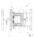
- FIG. 1 shows a sketch and, to illustrate the idea, a spray / embossing device 1 with a two-part molding or injection tool 2 and an injection area 2.3 (injection side) for the plastic and an embossing tool 3 (closing side) interacting with an injection tool part 2.1 (closing side), which has a two-part tool or pressure plate 4 which interacts with parts of the injection mold part 2.1 and is movable to the other injection mold part 2.2.
- the machine bed and clamping unit are not shown any further.
- the individual parts of an injection unit are also not taken into account in the illustration.
- the actual stamping process is considered.
- embossing stamp 5 which is in direct operative connection with the pressure plate 4.
- Spring elements 6 are integrated between the front pressure plate part 4.2 and the rear injection tool part 2.1.
- a toggle lever mechanism 7 is connected to the rear surface of the pressure plate part 4.1, which adjusts the injection tool part 2.1 and the pressure plate 4 relative to the injection tool part 2.2 during injection molding and for stamping. The mechanical connection between the pressure plate part 4.1 and the front injection tool part 2.1 is not shown.
- the injection mold 2 is closed in a known manner via the clamping unit, the actual injection process being initiated, which is done by injecting a plasticized plastic into the molded part or into the injection region 2.3 under pressure.
- the forces that occur against the entire pressure plate 4 during the injection process are absorbed by the spring elements 6 in order to prevent the pressure plate 4 from opening due to the internal pressure during the injection process.
- the injection process itself, with the closing of the injection tool 2, as shown in FIG.
- This adjustment of the stamp 5 takes place within the viscosity of the plastic after the first shaping by a slight adjustment of the stamp 5, approx. 1/10 sec, into the plastic or into the injection area 2.3, as shown in Fig. 2. This causes the plastic to be compressed in it Embossing area, which creates the wall of the plastic part in this area around the embossing stroke X is diluted. In the end, the device 1 are apart again driven and the plastic article removed from the injection mold 2.
- FIG. 3 shows a plastic article 10 produced in this way a key top 11 of an actuator, not shown, for example in automotive electronics.
- the area labeled 12 is thinner, than that marked with 13, which can be seen more clearly in FIG. 3a, which represents the key top 11 in section A-A of Fig. 3.
- the key top 11 shown is not the only plastic article 10, which can be produced by this method. So are also the CD's 20 mentioned at the beginning (FIG. 4) and other, different material thicknesses having plastic articles 10 can thus be produced.
- FIG. 5 View For the sake of completeness, one of the spring elements 6 is enlarged in FIG. 5 View shown.
- the springs 6.1 are further adjusted Pressure plate 4 deformed against the injection mold part 2.1 such that the two Areas of the pressure plate part 4.2 and of the rear injection tool part 2.1 to approach physically. As already described, this is the further imprint realized by the embossing stamp 5 within the plastic article 10, 20.
Landscapes
- Engineering & Computer Science (AREA)
- Manufacturing & Machinery (AREA)
- Mechanical Engineering (AREA)
- Moulds For Moulding Plastics Or The Like (AREA)
- Injection Moulding Of Plastics Or The Like (AREA)
Abstract
Description
Das kann dadurch erreicht werden, dass eine gegenüber einer Spritzform bewegbare Werkzeugplatte (Druckplatte) zweiteilig ausgebildet ist, die in ihrer Gesamtheit für das Spritzen und für das Prägen von einem Kniehebelgetriebe bewegt wird. Dabei ist ein an der Werkzeugplatte befestigter Prägestempel auf der selben Höhe wie die hintere Wand.
Während des Spritzgießens wird die gesamte Druckplatte bis zu einem vorgegebenen Anschlag verstellt, wobei Federelemente ein Öffnen beim Spritzen verhindern und der Kniehebel noch nicht in seine Endlage verfahren worden ist. Ist die vorbestimmte Schließposition für das Spritzgießen erreicht, und somit eine erste Formgebung geschaffen, erfolgt sich lückenlos anschließend und innerhalb der Viskosität des Kunststoffes eine weitere geringfügige Verstellung des Prägestempels in Richtung Einspritzbereich des Spritzwerkzeuges. Der Prägestempel wird dabei in das Kunststoffspritzteil gedrückt, wobei die Kunststoffwand in diesem Bereich komprimiert und dabei verdünnt oder getrennt wird. Das Kniegelenkgetriebe wird dazu innerhalb des Spritzprozesses und dem Prägevorgang gleichmäßig verfahren.
- Fig. 1
- eine Prinzipdarstellung der Vorrichtung vor dem Prägen,
- Fig. 2
- eine Darstellung der Vorrichtung nach dem Prägen,
- Fig. 3
- ein Darstellung eine nach dem Verfahren und mit der Vorrichtung hergestellten Bauteils,
- Fig. 3a
- eine Schnittdarstellung im Schnitt A-A aus Fig.3,
- Fig. 4
- ein weiteres mit der Vorrichtung herstellbares Kunststoffteil,
- Fig. 5
- in einer Ausschnittsdarstellung eines der Federelemente aus Fig. 1.
Wesentliche Teile des Prägewerkzeuges 3 sind neben der Druckplatte 4 ein Prägestempel 5, der mit der Druckplatte 4 in direkter Wirkverbindung steht. Zwischen dem vorderen Druckplattenteil 4.2 und dem hinteren Spritzwerkzeugteil 2.1 sind Federelemente 6 eingebunden. Mit der hinteren Fläche des Druckplattenteils 4.1 ist ein Kniehebelgetriebe 7 verbunden, welches das Spritzwerkzeugteil 2.1 und die Druckplatte 4 gegenüber dem Spritzwerkzeugteil 2.2 beim Spritzgießen und zum Prägen verstellt. Nicht näher dargestellt ist die mechanische Verbindung zwischen dem Druckplattenteil 4.1 und dem vorderen Spritzwerkzeugteil 2.1.
Der Spritzvorgang selbst ist mit Schließen des Spritzwerkzeuges 2, wie in Fig. 1 aufgezeigt, soweit fortgeschritten, dass der Prägevorgang sich dem Spritzvorgang nahtlos anschließen kann, so dass parallel dazu die Druckplatte 4 den Prägestempel 5 in das Formteil 2.3 verbringt, was durch weiteres Einwirken des bis dahin noch nicht in seine Endstellung verfahrenen Kniehebelgetriebes 7 auf die Druckplatte 4 erfolgt.
Claims (10)
- Verfahren zum Spritzprägen von insbesondere Kunststoffartikel wanddicker Unterschiede, wobei schon während eines Spritzprozesses ein Prägevorgang eingeleitet wird, dadurch gekennzeichnet, dassdas Schließen einer Spritz-/Prägevorrichtung (1) zum Prägen genutzt wird, wobeinach einer ersten Formgebung ein auf der Schließseite befindlicher Prägestempel (5) geringfügig derart verstellt wird, dass der im Einspritzbereich (2.3) befindliche Kunststoff im Prägebereich komprimiert und dabei dünnwandiger oder getrennt wird unddie Verstellung durch ein Kniegelenkgetriebe (7) erfolgt, welches ohne Unterbrechung innerhalb des Spritzprozesses und des Prägevorganges gleichmäßig verfahren wird.
- Verfahren nach Anspruch 1, dadurch gekennzeichnet, dass das Verstellen des Prägestempels (5) innerhalb der Viskosität des Kunststoffes nach der ersten Formgebung erfolgt.
- Verfahren nach Anspruch 1 oder 2, dadurch gekennzeichnet, dass der Prägestempels (5) geringfügig innerhalb eines Prägehubes (X) in den Kunststoff bzw. in den Einspritzbereich (2.3) hinein gedrückt wird.
- Verfahren nach Anspruch 3, dadurch gekennzeichnet, dass ein Nachdruck durch den Prägehub (X) realisiert wird.
- Spritz-/Prägevorrichtung zum Spritzprägen von insbesondere Kunststoffartikel wanddicker Unterschiede, aufweisend zumindest ein Spritzwerkzeug sowie ein Prägewerkzeug mit einem Prägestempel, dadurch gekennzeichnet, dassdas Prägewerkzeug (3) eine mit einem Teil (2.1) des Spritzwerkzeuges (2) zusammenwirkende zweiteilige Werkzeug- bzw. Druckplatte (4) aufweist,die mit ihrem hinteren Teil (4.2) mit dem Prägestempel (5.1) in Wirkverbindung stehen, wobeidas vordere Teil (4.1) der Druckplatte (4) mit einem Kniehebelgetrieb (7) verbunden ist.
- Spritz-/Prägevorrichtung nach Anspruch 4, dadurch gekennzeichnet, dass die Druckplatte (4) gleichzeitig Teil des Spritzwerkzeuges (2) ist.
- Spritz-/Prägevorrichtung nach einem der Ansprüche 4 oder 5, dadurch gekennzeichnet, dass zwischen der Druckplatte (4) und dem Spritzwerkzeugteil (2) Federelemente (6) eingebunden sind, die ein Öffnen beim Spritzen verhindern.
- Bauteil hergestellt nach dem Verfahren, aufweisend zumindest einen dünnwandigen und einen dickwandigeren Bereich (13).
- Bauteil nach Anspruch 8, dadurch gekennzeichnet, dass der dünnwandige Bereich (12) schlitzförmig ist.
- Bauteil nach Anspruch 8, dadurch gekennzeichnet, dass der dünnwandige Bereich (12) ein Loch ist.
Applications Claiming Priority (2)
| Application Number | Priority Date | Filing Date | Title |
|---|---|---|---|
| DE10226301 | 2002-06-13 | ||
| DE10226301A DE10226301B4 (de) | 2002-06-13 | 2002-06-13 | Vorrichtung und Verfahren zum Spritzprägen von Kunststoffartikeln sowie nach dem Verfahren hergestelltes Bauteil |
Publications (1)
| Publication Number | Publication Date |
|---|---|
| EP1371472A1 true EP1371472A1 (de) | 2003-12-17 |
Family
ID=29557799
Family Applications (1)
| Application Number | Title | Priority Date | Filing Date |
|---|---|---|---|
| EP03011505A Withdrawn EP1371472A1 (de) | 2002-06-13 | 2003-05-21 | Vorrichtung und Verfahren zum Spritzprägen sowie nach dem Verfahren hergestelltes Bauteil |
Country Status (2)
| Country | Link |
|---|---|
| EP (1) | EP1371472A1 (de) |
| DE (1) | DE10226301B4 (de) |
Cited By (3)
| Publication number | Priority date | Publication date | Assignee | Title |
|---|---|---|---|---|
| DE102005012106A1 (de) * | 2005-03-09 | 2006-09-14 | Decoma (Germany) Gmbh | Verfahren und Vorrichtung zum Herstellen von Bauteilen |
| CN109159354A (zh) * | 2018-10-12 | 2019-01-08 | 重庆大道泡沫塑料包装材料有限公司 | 包装膜生产线 |
| CN109159378A (zh) * | 2018-10-12 | 2019-01-08 | 重庆大道泡沫塑料包装材料有限公司 | 包装膜生产模具 |
Families Citing this family (1)
| Publication number | Priority date | Publication date | Assignee | Title |
|---|---|---|---|---|
| DE102010031192B4 (de) | 2010-07-09 | 2022-01-20 | Preh Gmbh | Lentikular-Leuchtvorrichtung und Bedienelement |
Citations (8)
| Publication number | Priority date | Publication date | Assignee | Title |
|---|---|---|---|---|
| DE1127579B (de) * | 1960-01-09 | 1962-04-12 | Ankerwerk Gebr Goller | Verfahren zum Betrieb einer Spritzgiessmaschine fuer die Herstellung von Formkoerpern aus thermoplastischen Kunststoffen |
| JPS59185637A (ja) * | 1983-04-06 | 1984-10-22 | Matsushita Electric Ind Co Ltd | 射出圧縮成形装置 |
| US4900242A (en) * | 1986-05-05 | 1990-02-13 | Maus Steven M | Apparatus for injection molding articles |
| JPH08323816A (ja) * | 1995-06-01 | 1996-12-10 | Honda Motor Co Ltd | 射出圧縮成形金型 |
| JPH0939058A (ja) * | 1995-07-25 | 1997-02-10 | Mitsubishi Materials Corp | 射出成形用金型装置 |
| JPH1034718A (ja) * | 1996-07-18 | 1998-02-10 | Toyo Mach & Metal Co Ltd | 射出成形機 |
| JPH10286850A (ja) * | 1997-04-14 | 1998-10-27 | Toyo Mach & Metal Co Ltd | 射出成形機の制御方法 |
| JPH10315283A (ja) * | 1997-05-21 | 1998-12-02 | Toyo Mach & Metal Co Ltd | 射出成形機とその射出成形方法 |
Family Cites Families (6)
| Publication number | Priority date | Publication date | Assignee | Title |
|---|---|---|---|---|
| DE8806805U1 (de) * | 1988-05-25 | 1988-07-07 | Potthoff, Rüdiger, 5882 Meinerzhagen | Spritzgießwerkzeug zur Herstellung von Kunststoffteilen großer, wanddicker Unterschiede auf Spritzgießmaschinen |
| DE4310791A1 (de) * | 1993-03-26 | 1994-09-29 | Saechsische Kunststofftechnik | Schließeinheit, insbesondere für Spritzgießmaschinen mit Kniehebelantrieb |
| GB2282560B (en) * | 1993-09-14 | 1997-12-17 | Idemitsu Petrochemical Co | Compression equipment of injection compression molding machine and injection compression molding machine |
| DE19531131C2 (de) * | 1995-08-24 | 1999-01-07 | Ferromatik Milacron Maschinenb | Vorrichtung zum Spritzprägen von insbesondere scheibenförmigen Kunststoffartikeln in einer Spritzgießmaschine |
| DE19745909A1 (de) * | 1997-10-17 | 1999-04-22 | Borealis Polymere Holding Gmbh | Differenzierter Preßprozeß |
| DE19842385A1 (de) * | 1998-09-16 | 2000-03-30 | Mannesmann Vdo Ag | Vorrichtung und Verfahren zum Spritzprägen |
-
2002
- 2002-06-13 DE DE10226301A patent/DE10226301B4/de not_active Expired - Lifetime
-
2003
- 2003-05-21 EP EP03011505A patent/EP1371472A1/de not_active Withdrawn
Patent Citations (8)
| Publication number | Priority date | Publication date | Assignee | Title |
|---|---|---|---|---|
| DE1127579B (de) * | 1960-01-09 | 1962-04-12 | Ankerwerk Gebr Goller | Verfahren zum Betrieb einer Spritzgiessmaschine fuer die Herstellung von Formkoerpern aus thermoplastischen Kunststoffen |
| JPS59185637A (ja) * | 1983-04-06 | 1984-10-22 | Matsushita Electric Ind Co Ltd | 射出圧縮成形装置 |
| US4900242A (en) * | 1986-05-05 | 1990-02-13 | Maus Steven M | Apparatus for injection molding articles |
| JPH08323816A (ja) * | 1995-06-01 | 1996-12-10 | Honda Motor Co Ltd | 射出圧縮成形金型 |
| JPH0939058A (ja) * | 1995-07-25 | 1997-02-10 | Mitsubishi Materials Corp | 射出成形用金型装置 |
| JPH1034718A (ja) * | 1996-07-18 | 1998-02-10 | Toyo Mach & Metal Co Ltd | 射出成形機 |
| JPH10286850A (ja) * | 1997-04-14 | 1998-10-27 | Toyo Mach & Metal Co Ltd | 射出成形機の制御方法 |
| JPH10315283A (ja) * | 1997-05-21 | 1998-12-02 | Toyo Mach & Metal Co Ltd | 射出成形機とその射出成形方法 |
Non-Patent Citations (9)
| Title |
|---|
| BREITENBACH J: "SPRITZPRAEGEN UND SEINE VARIATIONEN IN DER PRAXIS", PLASTVERARBEITER, ZEHNER AND HUETHIG VERLAG, SPEYER AM RHEIN, DE, vol. 19, no. 7, 1968, pages 517 - 524, XP009001827, ISSN: 0032-1338 * |
| HARTMANN, W.; DUNG, G.: "Bindenahtfreies Spritzen von Artikeln mit Durchbrüchen und örtlich dünnen Wandstellen", PLASTVERARBEITER, vol. 22, no. 11, November 1971 (1971-11-01), pages 780 - 784, XP009014376 * |
| JOHANNABER, F.; MICHAELI, W.: "Handbuch Spritzgiessen", November 2001, CARL HANSER VERLAG, MÜNCHEN, ISBN: 3-446-15632-1, XP002248792 * |
| PATENT ABSTRACTS OF JAPAN vol. 009, no. 046 (M - 360) 27 February 1985 (1985-02-27) * |
| PATENT ABSTRACTS OF JAPAN vol. 1997, no. 04 30 April 1997 (1997-04-30) * |
| PATENT ABSTRACTS OF JAPAN vol. 1997, no. 06 30 June 1997 (1997-06-30) * |
| PATENT ABSTRACTS OF JAPAN vol. 1998, no. 06 30 April 1998 (1998-04-30) * |
| PATENT ABSTRACTS OF JAPAN vol. 1999, no. 01 29 January 1999 (1999-01-29) * |
| PATENT ABSTRACTS OF JAPAN vol. 1999, no. 03 31 March 1999 (1999-03-31) * |
Cited By (4)
| Publication number | Priority date | Publication date | Assignee | Title |
|---|---|---|---|---|
| DE102005012106A1 (de) * | 2005-03-09 | 2006-09-14 | Decoma (Germany) Gmbh | Verfahren und Vorrichtung zum Herstellen von Bauteilen |
| DE102005012106B4 (de) * | 2005-03-09 | 2012-06-28 | Decoma (Germany) Gmbh | Werkzeug und Vorrichtung zum Prägen |
| CN109159354A (zh) * | 2018-10-12 | 2019-01-08 | 重庆大道泡沫塑料包装材料有限公司 | 包装膜生产线 |
| CN109159378A (zh) * | 2018-10-12 | 2019-01-08 | 重庆大道泡沫塑料包装材料有限公司 | 包装膜生产模具 |
Also Published As
| Publication number | Publication date |
|---|---|
| DE10226301A1 (de) | 2004-01-08 |
| DE10226301B4 (de) | 2004-09-23 |
Similar Documents
| Publication | Publication Date | Title |
|---|---|---|
| EP0671249B1 (de) | Verfahren und Vorrichtung zur Herstellung optischen Linsen | |
| DE3884183T2 (de) | Düsenkontaktmechanismus für spritzgiessmaschinen. | |
| DE3780151T2 (de) | Spritzgiesseinrichtung und verfahren. | |
| EP0824057A1 (de) | Verfahren und Vorrichtung zur Herstellung von Spritzgussteilen aus Kunststoff | |
| DE69623729T2 (de) | Spritzprägeverfahren zum Formen eines Brillenglases | |
| EP0424624A2 (de) | Spritzgiessform für Spritzgussteile aus plastifizierbarem Material, insbesondere aus plastifizierbaren Flüssigkristall-Polymeren | |
| DE69705570T2 (de) | Spritzprägeverfahren zum Formen von Linsen | |
| DE4432723A1 (de) | Preßvorrichtung einer Spritzprägemaschine und Spritzprägemaschine | |
| DE19639678B4 (de) | Formwerkzeug für den Einsatz in einer Spritzgussmaschine und Verfahren | |
| EP0074473B1 (de) | Verfahren und Vorrichtung zur Herstellung von Formteilen oder Gegenständen aus Kunststoff | |
| DE102024139030A1 (de) | Steuervorrichtung für spritzgiessmaschine | |
| DE10217584B4 (de) | Spritzgießeinrichtung | |
| EP1343621B1 (de) | Verfahren nud vorrichtung zum spritzgiessen von gewichtsgenauen flachen optischen datenträger | |
| DE4218822C2 (de) | Vorrichtung zum Auswerfen von Spritzgußteilen aus Spritzgußformen | |
| DE69021824T2 (de) | Verfahren zum Spritzgiessen und Vorrichtung dafür. | |
| DE10226301B4 (de) | Vorrichtung und Verfahren zum Spritzprägen von Kunststoffartikeln sowie nach dem Verfahren hergestelltes Bauteil | |
| EP1420930B1 (de) | Verfahren und vorrichtung zum automatischen herstellen dünner platten | |
| EP0605025A1 (de) | Spritzgiess- oder Spritzprägemaschine | |
| DE3516179A1 (de) | Verfahren und vorrichtung zum herstellen von gegenstaenden aus thermoplastischem kunststoff durch spritzgiessen | |
| EP1582333B1 (de) | Verfahren und Vorrichtung zum Tiefziehen und Ausstanzen von Behältern aus einer thermoplastischen Kunstofffolie | |
| EP1344628B1 (de) | Formwerkzeug zum Tiefziehen von Behältern aus thermoplastischem Kunstoff | |
| DE19714149C2 (de) | Vorrichtung zum Plastifizieren und Einspritzen von Thermoplasten in ein Spritzgießwerkzeug | |
| DE69904654T2 (de) | Verfahren zum Spritzgiessen von Gegenständen aus synthetischen Polymeren/Copolymeren | |
| DD286541A5 (de) | Werkzeug zum entformen hinterschnittener gummiformteile | |
| DE2909738A1 (de) | Formschliessvorrichtung an spritzgiessmaschinen zum spritzpraegen von kunststoffteilen |
Legal Events
| Date | Code | Title | Description |
|---|---|---|---|
| PUAI | Public reference made under article 153(3) epc to a published international application that has entered the european phase |
Free format text: ORIGINAL CODE: 0009012 |
|
| 17P | Request for examination filed |
Effective date: 20030604 |
|
| AK | Designated contracting states |
Kind code of ref document: A1 Designated state(s): AT BE BG CH CY CZ DE DK EE ES FI FR GB GR HU IE IT LI LU MC NL PT RO SE SI SK TR |
|
| AX | Request for extension of the european patent |
Extension state: AL LT LV MK |
|
| RAP1 | Party data changed (applicant data changed or rights of an application transferred) |
Owner name: PREH GMBH |
|
| AKX | Designation fees paid |
Designated state(s): DE ES FR IT |
|
| 17Q | First examination report despatched |
Effective date: 20100309 |
|
| STAA | Information on the status of an ep patent application or granted ep patent |
Free format text: STATUS: THE APPLICATION IS DEEMED TO BE WITHDRAWN |
|
| 18D | Application deemed to be withdrawn |
Effective date: 20110420 |