EP1371457B1 - Mechanism for generating a flame jet and gas combustion powered apparatus comprising said mechanism - Google Patents
Mechanism for generating a flame jet and gas combustion powered apparatus comprising said mechanism Download PDFInfo
- Publication number
- EP1371457B1 EP1371457B1 EP03291409A EP03291409A EP1371457B1 EP 1371457 B1 EP1371457 B1 EP 1371457B1 EP 03291409 A EP03291409 A EP 03291409A EP 03291409 A EP03291409 A EP 03291409A EP 1371457 B1 EP1371457 B1 EP 1371457B1
- Authority
- EP
- European Patent Office
- Prior art keywords
- chamber
- volume
- flame jet
- combustion
- port
- Prior art date
- Legal status (The legal status is an assumption and is not a legal conclusion. Google has not performed a legal analysis and makes no representation as to the accuracy of the status listed.)
- Expired - Lifetime
Links
- 230000007246 mechanism Effects 0.000 title claims abstract description 37
- 238000002485 combustion reaction Methods 0.000 title claims description 87
- 238000004891 communication Methods 0.000 claims description 9
- 239000000446 fuel Substances 0.000 description 34
- 239000000203 mixture Substances 0.000 description 14
- 238000000034 method Methods 0.000 description 11
- 230000008569 process Effects 0.000 description 11
- 239000007789 gas Substances 0.000 description 10
- 235000014676 Phragmites communis Nutrition 0.000 description 8
- 238000010926 purge Methods 0.000 description 6
- 239000000463 material Substances 0.000 description 5
- 230000001133 acceleration Effects 0.000 description 4
- 239000006227 byproduct Substances 0.000 description 4
- 230000014759 maintenance of location Effects 0.000 description 3
- 230000002000 scavenging effect Effects 0.000 description 3
- 230000009471 action Effects 0.000 description 2
- 230000006835 compression Effects 0.000 description 2
- 238000007906 compression Methods 0.000 description 2
- 230000007423 decrease Effects 0.000 description 2
- 230000003247 decreasing effect Effects 0.000 description 2
- 230000001419 dependent effect Effects 0.000 description 2
- 239000007787 solid Substances 0.000 description 2
- 230000004888 barrier function Effects 0.000 description 1
- 230000008859 change Effects 0.000 description 1
- 230000001351 cycling effect Effects 0.000 description 1
- 230000000694 effects Effects 0.000 description 1
- 238000005516 engineering process Methods 0.000 description 1
- 239000002737 fuel gas Substances 0.000 description 1
- 239000003292 glue Substances 0.000 description 1
- 230000006872 improvement Effects 0.000 description 1
- 238000002347 injection Methods 0.000 description 1
- 239000007924 injection Substances 0.000 description 1
- 230000001788 irregular Effects 0.000 description 1
- 239000002184 metal Substances 0.000 description 1
- 238000012986 modification Methods 0.000 description 1
- 230000004048 modification Effects 0.000 description 1
- 230000035515 penetration Effects 0.000 description 1
- 238000003825 pressing Methods 0.000 description 1
- VBUBYMVULIMEHR-UHFFFAOYSA-N propa-1,2-diene;prop-1-yne Chemical compound CC#C.C=C=C VBUBYMVULIMEHR-UHFFFAOYSA-N 0.000 description 1
- 230000035939 shock Effects 0.000 description 1
- 238000011144 upstream manufacturing Methods 0.000 description 1
Images


Classifications
-
- B—PERFORMING OPERATIONS; TRANSPORTING
- B25—HAND TOOLS; PORTABLE POWER-DRIVEN TOOLS; MANIPULATORS
- B25C—HAND-HELD NAILING OR STAPLING TOOLS; MANUALLY OPERATED PORTABLE STAPLING TOOLS
- B25C1/00—Hand-held nailing tools; Nail feeding devices
- B25C1/08—Hand-held nailing tools; Nail feeding devices operated by combustion pressure
Definitions
- the present invention relates to a mechanism for generating a flame jet, and more specifically to a two-volume combustion apparatus in which a flame jet is generated and transmitted from one volume into the other, particularly in conjunction with combustion-powered fastener driving tools.
- Such tools incorporate a generally pistol-shaped tool housing enclosing a small internal combustion engine.
- the engine is powered by a canister of pressurized fuel gas, also called a fuel cell.
- a battery-powered electronic power distribution unit produces a spark for ignition, and a fan located in a combustion chamber provides for both an efficient combustion within the chamber, while facilitating processes ancillary to the combustion operation of the device, Such ancillary processes include: inserting the fuel into the combustion chamber; mixing the fuel and air within the chamber; and removing, or scavenging, combustion by-products.
- the engine includes a reciprocating piston with an elongated, rigid driver blade disposed within a single cylinder body.
- a valve sleeve is axially reciprocable about the cylinder and, through a linkage, moves to close the combustion chamber when a work contact element at the end of the linkage is pressed against a workpiece. This pressing action also triggers a fuel metering valve to introduce a specified volume of fuel into the closed combustion chamber.
- the piston and driver blade Upon the pulling of a trigger switch, which causes the spark to ignite a charge of gas in the combustion chamber of the engine, the piston and driver blade are shot downward to impact a positioned fastener and drive it into the workpiece. The piston then returns to its original, or "ready” position, through differential gas pressures within the cylinder. Fasteners are fed magazine-style into the nosepiece, where they are held in a properly positioned orientation for receiving the impact of the driver blade.
- combustion in the chamber Upon ignition of the combustible fuel/air mixture, the combustion in the chamber causes the acceleration of the piston/driver blade assembly and the penetration of the fastener into the workpiece if the fastener is present.
- Combustion pressure in the chamber is an important consideration because it affects the amount of force with which the piston may drive the fastener. Another important consideration the amount of time required to drive the piston and complete the ancillary processes between combustion cycles of the engine.
- a typical operator of a combustion-powered tool will generally sense a delay when the time required to drive the fastener after pulling the trigger is more than approximately 35-50 milliseconds.
- There are other types of conventional combustion-powered tools which do not incorporate a fan in the combustion chamber.
- Single-chamber combustion systems are effective in achieving a fast combustion cycle time. This type of system, however, does not generally realize peak combustion pressures to drive a piston which are as high as those seen in other gas combustion-powered tools.
- One such conventional combustion-powered tool which yields decent peak combustion pressures is a two-chamber system, where at least one of the chambers has a tubular shape and is connected to the second chamber.
- the tubular shaped first chamber has a tube length L and a diameter D, and the ratio of L/D is known to be high, that is, between two and twenty, and preferably ten.
- a spark plug is located at one closed end of the first chamber, and the other end of this tubular chamber is in communication with the second chamber via a port.
- the port connecting the two chambers typically includes a reed valve, which remains normally closed to prevent back flow of pressure from the second chamber into the first tubular chamber.
- the first tubular chamber having a volume V1 operates as a compressor.
- a fuel/air mixture in V1 is ignited by the spark plug at the closed end of the tubular chamber, and advances a flame front toward the port end of the tube.
- unbumed fuel/air ahead of the flame front is pushed into the second chamber, or volume V2, and thereby compresses the fuel/air mixture in V2.
- the air/fuel mixture in V2 ignites.
- the ignited gas in V2 thus rapidly builds pressure in V2 and closes the reed valve to prevent loss of pressure back into V1.
- Longer tubular chambers are thus generally preferred as V1 because longer tubes are known to create greater pre-compression into V2.
- V1 tubes however, result in longer times between the spark at the closed end of V1 and the ignition of the air/fuel mixture in V2, which is undesirable.
- longer V2 ignition time also creates a need for a piston delay mechanism, such that the piston movement will begin immediately prior to where the pressure in V2 builds to a maximum obtainable pressure.
- a typical two-chamber system can take 35 milliseconds to reach peak pressure in V2 to drive a piston (not including time to complete the ancillary processes), which is about the amount of time where the tool operator will generally sense a delay in the tool's operation.
- the ancillary process time is also known to be greater for two-chamber systems than in single-chamber systems. The time to complete the ancillary processes becomes even greater as the length of the tubular first chamber V1 increases.
- a third known gas combustion system utilizes an "accelerator plate" placed in a single tubular volume, to effectively divide the volume in two.
- the accelerator plate itself includes multiple holes for communication between the two volumes, and fuel distribution is provided to both volumes separately through a common fuel supply line with two orifices.
- An operator of a device employing this system triggers fuel mixing via three-inch actuation.
- This type of device has been shown to allow repeatable combustion cycling.
- a drawback to accelerator plate systems, however, is that they tend to be bulky and cumbersome to operate. Also, a volume on one side of the accelerator plate may not be increased without necessarily decreasing the other volume.
- the present invention provides a mechanism for generating a flame jet according to claim 1.
- the mechanism of the present invention may also serve as the combustion chamber of a two-chamber combustion powered apparatus.
- the flame jet generated by the mechanism is propelled into a second chamber, which is in communication with the combustion chamber.
- Pressure generated within the second chamber may then drive a piston device connected to the second chamber.
- this mechanism is effective for generating rapid combustion cycles and high pressures in a separate chamber.
- the mechanism is particularly useful for generating, in a relatively compact geometry, rapid combustions and high pressures that are typically seen in larger and more cumbersome devices.
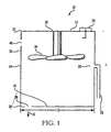
- a high-energy flame generating mechanism is generally designated 10, and includes a combustion chamber body 12 enclosing a volume which is defined by vertical structure 14 and two opposing horizontal structures 16 and 18.
- the structures 14, 16, 18 are preferably rigid metal bodies, but may also be formed from other strong, rigid, and combustion-resistant materials known in the art.
- One end of the vertical structure 14 is fixedly joined to horizontal structure 16 at a joint 20,'and the opposite end of the vertical structure 14 is fixedly joined to horizontal structure 18 at joint 22.
- the joints 20 and 22 preferably represent one continuous structure including structures 14 and 16, but may also be a weld, glue, compressed gasket, or other combustion-resistant joint capable of withstanding repeated pressures.
- the vertical structure 14 is preferably configured to form a cylinder or a tube, but may also be formed into any continuous structure, or series of structures, which correspond to outer dimensions of the horizontal structures 16 and 18.
- Horizontal structure 16 preferably has the shape of a rounded disk 24 with a diameter D and an outer perimeter 26. For example, where the vertical structure 14 is a cylinder, the diameter of the cylinder will match the diameter D of the disk 24.
- vertical structure 14 and horizontal structure 16 need not be at right angles relative to one another, or even be planar structures.
- Horizontal structure 16 may be bowl-shaped, for example, and have an outer diameter D different from that of horizontal structure 18.
- vertical structure 14 may arced so that a continuous body formed by the vertical structure 14 and the horizontal structure 16 is hemispherical or parabolic in shape, as shown in FIG. 1A .
- any number of irregular three-dimensional shapes may also be used for vertical structure 14 and horizontal structures 16 and 18 to form a volume for the chamber body 12, without departing from the present invention.
- the joint 20 joins the outer perimeter 26 of the horizontal structure 16 where it contacts the cylinder diameter at one end of the vertical structure 14.
- the horizontal structure 18 has the same dimensions as horizontal structure 16, and similarly joins a cylinder diameter of the opposite end of the vertical structure 14 at the joint 22.
- the vertical structure 14 of the cylinder has a length L such that the aspect ratio of L/D is preferably less than 2. Because a compact structure is preferable in tools or systems employing the mechanism 10, an aspect ratio of 1, or 1 ⁇ 2, is even more desirable.
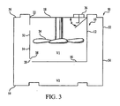
- a combustible fuel is fed into the chamber 12 from a fuel line 28, through a fuel aperture 30, which is located on a wall 32 of the vertical structure 14, and preferably in a low pressure area of the chamber 12 upstream of a fan 34.
- a fuel is MAPP gas of the type used in combustion-powered fastener driving tools
- the fuel may be any of a number of known combustible fuels practiced in the art.
- the fuel mixes with air in the chamber 12 to create a combustible gas.
- the fan 34 is located within the chamber 12 and rotates in a plane generally parallel to a plane defined by either of the horizontal structures 16 or 18. The rotating fan 34 rapidly and evenly mixes the fuel with the air in the chamber 12.
- An even fuel/air mixture is desirable to provide a consistent and predictable operation of the mechanism 10. The more rapidly an even fuel/air mixture is obtained, the less time is then required between repeated cycles or uses of the mechanism, which is also desirable.
- An ignition source 36 for igniting the fuel/air mixture is provided within the chamber 12, and is preferably located on the horizontal structure 18.
- the ignition source 36 is preferably a spark plug, but may also be any device known in the art for enabling a rapid and controlled ignition of the combustible gas.
- the ignition source 36 Upon a signal from an operator, the ignition source 36 generates a spark which ignites the combustible fuel/air mixture in the chamber 12 in the area of the ignition source 36, whereby a flame front is created that travels from the ignition source 36 to the opposite end of the chamber 12.
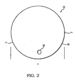
- Having a surface area similar to a spherical wave front the flame front travels outward from the ignition source 36.
- the time required to ignite the fuel in the chamber 12 is dependent upon the surface area of the flame front.
- the present inventors have discovered that the turbulence created by the fan 34 significantly increases the surface area of the moving flame front. The greater flame front surface area therefore allows a much faster combustion of the fuel/air mixture in the chamber
- the pressure from combustion causes a flame to be propelled out of the chamber 12 through a flame jet port 38 as a high energy flame jet which travels outside of the chamber 12 in the general direction designated A.
- the flame jet port 38 is preferably located on the horizontal structure 16 at a sufficient distance from the ignition source 36 to enhance the flame acceleration. In one preferred embodiment, the flame jet port 38 is located 270 degrees from the ignition source 36, in a vertical plane where the ignition source 36 is located at 0 degrees.
- the rotating fan 34 also facilitates a more rapid scavenging of the chamber 12.
- the scavenging process is further assisted by at least one recirculation port 40, which is preferably located on the vertical structure 14 between the plane of rotation of the fan 34 and the ignition source 36.
- the recirculation port 40 also assists in fuel mixing -- one of the ancillary processes.
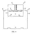
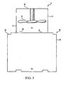
- an alternate combustion apparatus is generally designated 50, and incorporates the flame-generating mechanism 10 into a two-chamber configuration.
- the combustion chamber 12 serves as the first chamber of the apparatus 50.
- a second chamber 52 is also provided and functions as the other chamber of the two-chamber apparatus 50.
- the second chamber 52 has an overall shape geometry similar to that of the combustion chamber 12, and is also formed from the same solid, rigid, and combustion-resistant materials.
- the second chamber 52 has a generally vertical wall 54 and two opposing upper and lower horizontal walls 56, 58, whose dimensions, however, do not necessarily correspond to the dimensions of similar structures of the combustion chamber 12. It is contemplated that the precise shape of the wall 54 may vary to suit the particular device or application, and may include round or other non-linear dimensions. It is similarly contemplated that the dimensions of chamber 12 may also be non-linear to suit the particular device or application.
- the chambers 12 and 52 are configured so that a flame may be produced in combustion chamber 12 and will progressively move into the second chamber 52 as a high-speed jet of flame from the flame jet port 38.
- a volume V1 is defined by the combustion chamber 12, and a volume V2 is defined by the second chamber 52.
- the combustion chamber 12 is located partially or entirely within second chamber 52.
- FIG. 4 shows the apparatus 50 with the chamber 12 partially located within the chamber 52.
- the volume V2 is defined by the entire volume within the dimensions of the second chamber 52, minus any volume occupied by the combustion chamber 12.
- the volume V2 can vary depending on the location of the chamber 12, without any change in the volume V1 or the dimensions of the second chamber 52.
- the second, or upper, horizontal structure 18 of the combustion chamber 12 may even be formed of a portion of the upper horizontal wall 56 of the chamber 52, with the vertical structure 14 and first horizontal structure 16 then forming a cup-shaped divider between the volumes V1 and V2.
- the first horizontal structure 16 may instead be formed from a. portion of the horizontal wall 56.
- the chambers 12 and 52 are relatively located so that the volumes V1 and V2 are in communication through the flame jet port 38, and so that the mechanism 10 creates combustion pressures in the volume V2.
- the rotation of the fan 34 introduces a swirl in the combustion chamber 12, and that combustion pressures in the volume V2 improve when the flame jet port 38 is located downstream of the spark from the ignition source 36 in the direction of the swirl.
- the preferred angle ⁇ from the ignition source 36 to the flame jet port 38 varies according to the dimensions of the combustion chamber 12 and the rotation speed of the fan 34.
- the flame jet port 38 is located at the joint 20 at a point which maximizes the distance between the flame jet port 38 and the ignition source 36.
- a design goal is to displace the flame jet port 38 at a distance from the ignition source 36 to allow for maximum acceleration of the flame within the chamber 12, but without greatly increasing time required for the flame to travel from the ignition source 36 to the flame jet port 38.
- an alternate flame-generating mechanism is generally designated 60.
- the flame jet port 38 is centrally located on the first horizontal structure 16.
- space considerations make a central port location desirable.
- sufficient distance is not available within the chamber 12 for the flame jet to travel from the ignition source 36 to achieve maximum flame acceleration.
- the present inventors have discovered that a shroud 62 may be placed over the flame jet port 38 on the interior of the combustion chamber 12, which effectively creates an additional distance for the flame to travel around the shroud 62.
- the flame travels into an opening 64 of the shroud 62 which is located at a preferred distance away from the port 38.
- the shroud 62 may be of any shape which provides a channel that requires the flame to travel a preferred distance. It is also contemplated that a similar shroud structure may be incorporated into mechanisms employing flame jet ports not centrally located, or employing multiple flame jet ports, where a greater flame travel distance is also desirable.
- flame jet speeds of up to and greater than sonic velocity have been realized passing through the flame jet port 38.
- the flame jet speed is generally temperature-dependent. At flame temperature, for example, the present invention can realize flame jet speeds of up to 1000 /meters per second (m/s).
- the average flame jet speeds are greater than 300 m/s for the foregoing configurations. This average flame jet speed is approximately 5-10 times or more the speed of the flame jet that would have been expected in conventional two-chamber systems. This improvement is even more noticeable when compared with the average flame speed in the conventional single-chamber with fan system, which average 20-30 m/s.
- a choked flow condition in the flame jet port limits the velocity of the flame jet to the speed of sound for normal configurations of the present invention.
- the present inventors have discovered that flame jet velocities into the volume V2 greater than the sonic velocity may be achieved by using super-sonic nozzles in place of the flame jet port 38. As the flame jet velocity in the volume V2 increases beyond the speed of sound, even stronger ignition will be achieved in the volume V2, which will in turn result in more rapid combustion and greater combustion pressure.
- FIGS. 7A-7D several supersonic nozzles 65a-d are shown having a sectional "converging-diverging" configuration.
- the supersonic nozzles thus become the communication path of combustion between volumes V1 and V2.
- the converging/diverging shape of the supersonic nozzles further energizes the flame jet entering the volume V2 and thus increases the burn rate of the air/fuel mixture in the volume V2.
- the converging/diverging design for the supersonic nozzle is preferred, other configurations are contemplated which would also allow passage of a flame jet having a velocity greater than the speed of sound.
- Reed valves are useful for allowing only unidirectional flow through ports. Reed valves remain normally closed, but open only when pressure on one side of the valve reaches a sufficient threshold. While reed valves are effective for preventing backflow from the volume V2 into the volume V1, because they stay normally closed and only allow flow in one direction, they can be counterproductive to rapid completion of the non-combustion ancillary processes between the higher-pressure combustion events.
- louvers 66 and 68 are respectively located on the recirculation port 40 and the flame jet port 38, and are preferably formed from the same solid, rigid, and combustion-resistant materials as the chamber 12.
- the louvers 66, 68 are spring-biased to remain open and allow airflow into and out of the chamber 12. Unlike reed valves, the louvers 66, 68 remain normally open, and only close when the pressure on one side of the louver reaches a threshold. Because the louvers 66, 68 are normally open, greater airflow is allowed through the chamber 12 in between combustion events, thereby decreasing the time required to complete the ancillary processes.
- the louvers 66, 68 close when the force of pressure in volume V2 is greater than the louver spring-bias force.
- the present inventors have discovered, however, that a sufficient pressure in the volume V2 may still be achieved if the recirculation port 40 remains open during combustion, even though the pressure in volume V2 is not as high as would be seen with the use of a reed valve, or the louver 66.
- Backflow through the port 40, from a gap between the vertical structure 14 and the vertical wall 54, is thus not a significant concern using to the improved configuration of the present invention.
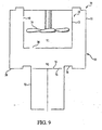
- a gas combustion-powered piston tool is generally designated 70, and incorporates the two-chamber apparatus 50 into its configuration.
- the apparatus 50 contacts a cylinder 72 slidably accommodating a piston 74 through an opening 76 in the lower horizontal wall 58.
- the piston 74 and a radically flared end 78 of the piston chamber 72 form a portion of the horizontal wall 58.
- a rapid increase in combustion pressure in the volume V2 drives the piston 74 down the piston chamber 72 in a direction away from the apparatus 50.
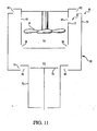
- an alternate tool is generally designated 80, and incorporates the apparatus 50, but now employing a plurality of flame jet ports 38 and recirculation ports 40.
- the additional ports facilitate greater airflow through the combustion chamber 12 and the second chamber 52 during the combustion cycle, as well as during purging, where combustion by-products within the chambers are removed and clean air enters.
- FIG. 11 shows the tool 80 in a purging condition, where the second chamber 52 movably disengages from the combustion chamber 12 and the piston chamber 72 to provide first and second openings 82 and 84 respectively in the volume V2.
- Clean air preferably flows into the volume V2 through the first opening 82, and then into the volume V1 through the recirculation ports 40
- Combustion by-products are preferably flushed out of the volume V1 through the flame jet ports 38, and then out of the volume V2 through the second opening 84.
- the second chamber 52 movably reengages the combustion chamber 12 and the piston chamber 72 to seal the volume V2 to allow fuel injection for the next combustion cycle.
- a further alternate tool is generally designated 90, and also incorporates the apparatus 50, and the movingly disengaging the second chamber 52 shown in FIG. 11 .
- the vertical structure 14 of the combustion chamber 12 movably disengage from the horizontal structure 18 to form an opening 92 at the joint 24. While disengaged, the opening 92 allows airflow into the combustion chamber to perform the function of the recirculation ports discussed above.
- the horizontal structure 16 is fixed, and the vertical structure 14 may also movably disengage from the horizontal structure 16 to form an opening 94 at the joint 20, to allow even greater airflow through the combustion chamber 12 during purging the volumes V1 and V2.
- chambers 12 and 52 may disengage to open and close together, or independently.
- the second chamber 52 is preferably joined to the combustion chamber 12 by a retention member 96.
- the retention member 96 is preferably a combustion-resistant flexible webbing which allows airflow and fuel mixture, but may also be made from any flexible combustion-resistant material known in the art.
- the retention member 96 may be rigid enough to force chambers 12 and 52 to open and close together, or flexible enough to allow chambers 12 and 52 to move independently.
- the second chamber 52 reengages to close the openings 82 and 84 to seal the volume V2 before the vertical structure 14 reengages to close the openings 92 and 94 and seal the volume V1.
- the volume V1 thus briefly remains open to allow greater fuel movement and mixture between the volumes V1 and V2.
- the tool 90 should then be fired after the vertical structure 14 reengages to seal the volume V1.
- the compact geometry of the apparatus 50 avoids the need for a piston delay device in the tool 80.
- the improved configuration of the present invention also reduces the amount of material required to house the tool 80.
- the reduced combustion time experienced by the present invention will additionally yield a decrease in heat lost to chamber walls.
- the negative effects caused by heat loss are even further improved by the action of the fan 34, which additionally cools the internal components of the tool 80.
- the improved flow and circulation of the apparatus 50 also functions to prevent flooding of the combustion chamber 12 if a user activates the tool 80 without creating a spark in the chamber 12.
- combustion apparatuses such as in the present invention, may also be effectively employed in other devices which drive a piston, or devices that may be powered by combustion apparatus in general. While particular embodiments of the combustion mechanism of the present invention have been shown and described, it will also be appreciated by those skilled in the art that changes and modifications may be made thereto without departing from the invention as set forth in the following claims.
Landscapes
- Engineering & Computer Science (AREA)
- Chemical & Material Sciences (AREA)
- Combustion & Propulsion (AREA)
- Mechanical Engineering (AREA)
- Portable Nailing Machines And Staplers (AREA)
- Gas Burners (AREA)
- Combustion Of Fluid Fuel (AREA)
- Ignition Installations For Internal Combustion Engines (AREA)
Applications Claiming Priority (2)
| Application Number | Priority Date | Filing Date | Title |
|---|---|---|---|
| US170736 | 2002-06-13 | ||
| US10/170,736 US6779493B2 (en) | 2002-06-13 | 2002-06-13 | Combustion mechanism for generating a flame jet |
Publications (3)
| Publication Number | Publication Date |
|---|---|
| EP1371457A2 EP1371457A2 (en) | 2003-12-17 |
| EP1371457A3 EP1371457A3 (en) | 2006-11-22 |
| EP1371457B1 true EP1371457B1 (en) | 2008-09-17 |
Family
ID=29250032
Family Applications (1)
| Application Number | Title | Priority Date | Filing Date |
|---|---|---|---|
| EP03291409A Expired - Lifetime EP1371457B1 (en) | 2002-06-13 | 2003-06-13 | Mechanism for generating a flame jet and gas combustion powered apparatus comprising said mechanism |
Country Status (13)
| Country | Link |
|---|---|
| US (1) | US6779493B2 (enExample) |
| EP (1) | EP1371457B1 (enExample) |
| JP (1) | JP2004074396A (enExample) |
| KR (1) | KR20030096056A (enExample) |
| AT (1) | ATE408477T1 (enExample) |
| AU (1) | AU2003204595B2 (enExample) |
| BR (1) | BR0302136A (enExample) |
| CA (1) | CA2432312C (enExample) |
| DE (1) | DE60323564D1 (enExample) |
| MX (1) | MXPA03005370A (enExample) |
| NZ (1) | NZ526430A (enExample) |
| PL (1) | PL201302B1 (enExample) |
| PT (1) | PT1371457E (enExample) |
Families Citing this family (14)
| Publication number | Priority date | Publication date | Assignee | Title |
|---|---|---|---|---|
| FR2852546B1 (fr) * | 2003-03-19 | 2006-08-11 | Prospection & Inventions | Procedes de reglage de la puissance d'un appareil a fonctionnement a gaz |
| FR2852547B1 (fr) * | 2003-03-19 | 2006-05-12 | Prospection & Inventions | Appareils a fonctionnement a gaz a chambre de pre-compression et chambre de propulsion |
| US6863045B2 (en) * | 2003-05-23 | 2005-03-08 | Illinois Tool Works Inc. | Combustion apparatus having improved airflow |
| US6964553B2 (en) * | 2003-05-23 | 2005-11-15 | Illinois Tool Works Inc. | Port for a fan chamber |
| DE602004009737T2 (de) * | 2003-11-07 | 2008-08-28 | Makita Corp., Anjo | Verbrennungsmotorwerkzeug |
| JP4395841B2 (ja) * | 2004-09-29 | 2010-01-13 | 日立工機株式会社 | 燃焼式打込み工具 |
| JP5384282B2 (ja) * | 2009-10-07 | 2014-01-08 | 株式会社マキタ | 燃焼式作業工具 |
| FR3001172B1 (fr) * | 2013-01-18 | 2015-06-05 | Illinois Tool Works | Appareil de fixation electropneumatique a gaz |
| EP3034240A1 (de) * | 2014-12-19 | 2016-06-22 | HILTI Aktiengesellschaft | Eintreibgerät mit Durchführung in eine Brennkammer |
| EP3189938B1 (fr) * | 2015-03-10 | 2020-03-11 | Illinois Tool Works Inc. | Perfectionnements pour un outil de fixation à gaz |
| CN107921614A (zh) * | 2015-09-14 | 2018-04-17 | 喜利得股份公司 | 具有增压的燃气运行的驱入工具 |
| CN107332109A (zh) * | 2017-04-26 | 2017-11-07 | 周向进 | 一种喷火的火花塞及其内燃机和汽车 |
| US11179837B2 (en) | 2017-12-01 | 2021-11-23 | Illinois Tool Works Inc. | Fastener-driving tool with multiple combustion chambers and usable with fuel canisters of varying lengths |
| CN113280327B (zh) * | 2021-05-31 | 2024-09-13 | 湖南鑫迪新能源科技有限公司 | 一种燃烧机及含此燃烧机的烘烤设备 |
Family Cites Families (30)
| Publication number | Priority date | Publication date | Assignee | Title |
|---|---|---|---|---|
| US3042008A (en) * | 1958-10-18 | 1962-07-03 | Liesse Maurice | Striking machine, chiefly nailing, clamping and the like percussion machines |
| US3967771A (en) * | 1974-12-16 | 1976-07-06 | Smith James E | Self-contained impact tool |
| US4510748A (en) | 1979-11-05 | 1985-04-16 | Adams Joseph S | Compression wave former |
| US4365471A (en) | 1979-11-05 | 1982-12-28 | Adams Joseph S | Compression wave former |
| US4292935A (en) * | 1980-03-31 | 1981-10-06 | Rockwell International Corporation | Low nitrous oxide (NOX) precombustor |
| IN157475B (enExample) * | 1981-01-22 | 1986-04-05 | Signode Corp | |
| US4403722A (en) | 1981-01-22 | 1983-09-13 | Signode Corporation | Combustion gas powered fastener driving tool |
| US4483474A (en) * | 1981-01-22 | 1984-11-20 | Signode Corporation | Combustion gas-powered fastener driving tool |
| EP0102411A1 (en) * | 1982-09-08 | 1984-03-14 | Joseph S. Adams | Compression wave former |
| US4483473A (en) * | 1983-05-02 | 1984-11-20 | Signode Corporation | Portable gas-powered fastener driving tool |
| US4589398A (en) * | 1984-02-27 | 1986-05-20 | Pate Ronald C | Combustion initiation system employing hard discharge ignition |
| US4759318A (en) | 1985-02-21 | 1988-07-26 | Joseph Adams Technical Arts Ltd. | Differential piston and valving system for detonation device |
| US4665868A (en) | 1985-02-21 | 1987-05-19 | Joseph Adams Technical Arts Ltd. | Differential piston and valving system for detonation device |
| JPS62297076A (ja) * | 1986-06-13 | 1987-12-24 | 日立工機株式会社 | ガス燃焼式ピストン駆動装置 |
| US4773581A (en) | 1986-06-13 | 1988-09-27 | Hitachi Koki Company, Ltd. | Combustion gas powered tool |
| JPS6393573A (ja) * | 1986-10-09 | 1988-04-23 | 日立工機株式会社 | 内燃式ピストン駆動工具の掃気装置 |
| US5197646A (en) * | 1992-03-09 | 1993-03-30 | Illinois Tool Works Inc. | Combustion-powered tool assembly |
| FR2730443B1 (fr) * | 1995-02-15 | 1997-04-11 | Spit Soc Prospect Inv Techn | Appareil de scellement a piston propulse par gaz comprime |
| US5713313A (en) * | 1997-02-07 | 1998-02-03 | Illinois Tool Works Inc. | Combustion powered tool with dual fans |
| DE19950342C2 (de) | 1999-10-19 | 2002-04-04 | Hilti Ag | Vorrichtung zum Antrieb eines Kolbens eines brennkraftbetriebenen Arbeitsgeräts mit Brennkammerverriegelung |
| DE19950352C2 (de) | 1999-10-19 | 2002-03-07 | Hilti Ag | Tragbares, brennkraftbetriebenes Arbeitsgerät und Verfahren zum Antrieb seines Kolbens |
| DE19962599C2 (de) | 1999-12-23 | 2002-09-19 | Hilti Ag | Tragbares, brennkraftbetriebenes Arbeitsgerät, insbesondere Setzgerät für Befestigungselemente, sowie Verfahren zu seiner Betriebssteuerung |
| DE19962598C2 (de) | 1999-12-23 | 2002-03-14 | Hilti Ag | Tragbares, brennkraftbetriebenes Arbeitsgerät, insbesondere Setzgerät für Befestigungselemente und Verfahren zu seiner Betriebssteuerung |
| DE19962695B4 (de) | 1999-12-23 | 2006-02-16 | Hilti Ag | Tragbares, brennkraftbetriebenes Arbeitsgerät mit veränderbarer Hauptkammer |
| DE19962711C2 (de) | 1999-12-23 | 2002-06-27 | Hilti Ag | Tragbares, brennkraftbetriebenes Arbeitsgerät mit veränderbarer Vorkammer |
| DE19962698C2 (de) | 1999-12-23 | 2002-09-19 | Hilti Ag | Brennkraftbetriebenes Arbeitsgerät mit Brennkammer-Druckregulierung |
| DE19962597C2 (de) | 1999-12-23 | 2002-07-04 | Hilti Ag | Tragbares, brennkraftbetriebenes Arbeitsgerät und Verfahren zum Bereitstellen eines Gasgemisches in seiner Brennkammer |
| DE10007211C2 (de) | 2000-02-17 | 2003-03-20 | Hilti Ag | Brennkraftbetriebenes Arbeitsgerät, insbesondere Setzgerät für Befestigungselemente |
| US6619527B1 (en) * | 2000-10-10 | 2003-09-16 | Illinois Tool Works Inc. | Combustion powered tool suspension for iron core fan motor |
| JP3969195B2 (ja) * | 2002-06-03 | 2007-09-05 | 日立工機株式会社 | ガス釘打機 |
-
2002
- 2002-06-13 US US10/170,736 patent/US6779493B2/en not_active Expired - Fee Related
-
2003
- 2003-06-10 AU AU2003204595A patent/AU2003204595B2/en not_active Ceased
- 2003-06-11 PL PL360637A patent/PL201302B1/pl unknown
- 2003-06-12 NZ NZ526430A patent/NZ526430A/en not_active IP Right Cessation
- 2003-06-12 KR KR10-2003-0037886A patent/KR20030096056A/ko not_active Withdrawn
- 2003-06-13 DE DE60323564T patent/DE60323564D1/de not_active Expired - Lifetime
- 2003-06-13 CA CA002432312A patent/CA2432312C/en not_active Expired - Fee Related
- 2003-06-13 AT AT03291409T patent/ATE408477T1/de not_active IP Right Cessation
- 2003-06-13 EP EP03291409A patent/EP1371457B1/en not_active Expired - Lifetime
- 2003-06-13 JP JP2003169350A patent/JP2004074396A/ja active Pending
- 2003-06-13 PT PT03291409T patent/PT1371457E/pt unknown
- 2003-06-13 BR BR0302136-0A patent/BR0302136A/pt not_active IP Right Cessation
- 2003-06-13 MX MXPA03005370A patent/MXPA03005370A/es active IP Right Grant
Also Published As
| Publication number | Publication date |
|---|---|
| NZ526430A (en) | 2003-10-31 |
| ATE408477T1 (de) | 2008-10-15 |
| PT1371457E (pt) | 2008-12-18 |
| JP2004074396A (ja) | 2004-03-11 |
| EP1371457A3 (en) | 2006-11-22 |
| BR0302136A (pt) | 2004-08-17 |
| DE60323564D1 (de) | 2008-10-30 |
| MXPA03005370A (es) | 2005-07-01 |
| CA2432312C (en) | 2008-08-26 |
| AU2003204595A1 (en) | 2004-01-15 |
| US20030230255A1 (en) | 2003-12-18 |
| AU2003204595B2 (en) | 2004-12-09 |
| PL201302B1 (pl) | 2009-03-31 |
| CA2432312A1 (en) | 2003-12-13 |
| KR20030096056A (ko) | 2003-12-24 |
| PL360637A1 (en) | 2003-12-15 |
| EP1371457A2 (en) | 2003-12-17 |
| US6779493B2 (en) | 2004-08-24 |
Similar Documents
| Publication | Publication Date | Title |
|---|---|---|
| EP1479483B1 (en) | Combustion apparatus having improved airflow | |
| EP1371457B1 (en) | Mechanism for generating a flame jet and gas combustion powered apparatus comprising said mechanism | |
| US4712379A (en) | Manual recycler for detonating impact tool | |
| US7484648B2 (en) | Combustion-engined setting tool | |
| CA2469430C (en) | Gas-operated apparatus with combustion chamber | |
| CA2544999A1 (en) | Combustion apparatus having collapsible volume | |
| EP1606081B1 (en) | Gas-operated apparatuses with precompression chamber and propulsion chamber | |
| US6964553B2 (en) | Port for a fan chamber |
Legal Events
| Date | Code | Title | Description |
|---|---|---|---|
| PUAI | Public reference made under article 153(3) epc to a published international application that has entered the european phase |
Free format text: ORIGINAL CODE: 0009012 |
|
| AK | Designated contracting states |
Kind code of ref document: A2 Designated state(s): AT BE BG CH CY CZ DE DK EE ES FI FR GB GR HU IE IT LI LU MC NL PT RO SE SI SK TR |
|
| AX | Request for extension of the european patent |
Extension state: AL LT LV MK |
|
| RIN1 | Information on inventor provided before grant (corrected) |
Inventor name: TOULOUSE, BRUNO Inventor name: FABIN, JOSEPH E. Inventor name: VAN ERDEN, DONALD L. Inventor name: URBAN, RICHARD Inventor name: RICORDI, CHRISTIAN PAUL ANDRE Inventor name: MOELLER, LARRY M. Inventor name: DOHERTY, JAMES E. Inventor name: ROBINSON, JAMES W. |
|
| PUAL | Search report despatched |
Free format text: ORIGINAL CODE: 0009013 |
|
| AK | Designated contracting states |
Kind code of ref document: A3 Designated state(s): AT BE BG CH CY CZ DE DK EE ES FI FR GB GR HU IE IT LI LU MC NL PT RO SE SI SK TR |
|
| AX | Request for extension of the european patent |
Extension state: AL LT LV MK |
|
| 17P | Request for examination filed |
Effective date: 20070521 |
|
| AKX | Designation fees paid |
Designated state(s): AT BE BG CH CY CZ DE DK EE ES FI FR GB GR HU IE IT LI LU MC NL PT RO SE SI SK TR |
|
| 17Q | First examination report despatched |
Effective date: 20070823 |
|
| GRAP | Despatch of communication of intention to grant a patent |
Free format text: ORIGINAL CODE: EPIDOSNIGR1 |
|
| GRAS | Grant fee paid |
Free format text: ORIGINAL CODE: EPIDOSNIGR3 |
|
| GRAA | (expected) grant |
Free format text: ORIGINAL CODE: 0009210 |
|
| AK | Designated contracting states |
Kind code of ref document: B1 Designated state(s): AT BE BG CH CY CZ DE DK EE ES FI FR GB GR HU IE IT LI LU MC NL PT RO SE SI SK TR |
|
| REG | Reference to a national code |
Ref country code: GB Ref legal event code: FG4D |
|
| REG | Reference to a national code |
Ref country code: CH Ref legal event code: EP |
|
| REG | Reference to a national code |
Ref country code: IE Ref legal event code: FG4D |
|
| REF | Corresponds to: |
Ref document number: 60323564 Country of ref document: DE Date of ref document: 20081030 Kind code of ref document: P |
|
| REG | Reference to a national code |
Ref country code: PT Ref legal event code: SC4A Free format text: AVAILABILITY OF NATIONAL TRANSLATION Effective date: 20081205 |
|
| REG | Reference to a national code |
Ref country code: SE Ref legal event code: TRGR |
|
| PG25 | Lapsed in a contracting state [announced via postgrant information from national office to epo] |
Ref country code: SI Free format text: LAPSE BECAUSE OF FAILURE TO SUBMIT A TRANSLATION OF THE DESCRIPTION OR TO PAY THE FEE WITHIN THE PRESCRIBED TIME-LIMIT Effective date: 20080917 Ref country code: FI Free format text: LAPSE BECAUSE OF FAILURE TO SUBMIT A TRANSLATION OF THE DESCRIPTION OR TO PAY THE FEE WITHIN THE PRESCRIBED TIME-LIMIT Effective date: 20080917 |
|
| NLV1 | Nl: lapsed or annulled due to failure to fulfill the requirements of art. 29p and 29m of the patents act | ||
| PG25 | Lapsed in a contracting state [announced via postgrant information from national office to epo] |
Ref country code: ES Free format text: LAPSE BECAUSE OF FAILURE TO SUBMIT A TRANSLATION OF THE DESCRIPTION OR TO PAY THE FEE WITHIN THE PRESCRIBED TIME-LIMIT Effective date: 20081228 Ref country code: BG Free format text: LAPSE BECAUSE OF FAILURE TO SUBMIT A TRANSLATION OF THE DESCRIPTION OR TO PAY THE FEE WITHIN THE PRESCRIBED TIME-LIMIT Effective date: 20081217 |
|
| PG25 | Lapsed in a contracting state [announced via postgrant information from national office to epo] |
Ref country code: RO Free format text: LAPSE BECAUSE OF FAILURE TO SUBMIT A TRANSLATION OF THE DESCRIPTION OR TO PAY THE FEE WITHIN THE PRESCRIBED TIME-LIMIT Effective date: 20080917 Ref country code: SK Free format text: LAPSE BECAUSE OF FAILURE TO SUBMIT A TRANSLATION OF THE DESCRIPTION OR TO PAY THE FEE WITHIN THE PRESCRIBED TIME-LIMIT Effective date: 20080917 Ref country code: NL Free format text: LAPSE BECAUSE OF FAILURE TO SUBMIT A TRANSLATION OF THE DESCRIPTION OR TO PAY THE FEE WITHIN THE PRESCRIBED TIME-LIMIT Effective date: 20080917 Ref country code: CZ Free format text: LAPSE BECAUSE OF FAILURE TO SUBMIT A TRANSLATION OF THE DESCRIPTION OR TO PAY THE FEE WITHIN THE PRESCRIBED TIME-LIMIT Effective date: 20080917 |
|
| PLBE | No opposition filed within time limit |
Free format text: ORIGINAL CODE: 0009261 |
|
| STAA | Information on the status of an ep patent application or granted ep patent |
Free format text: STATUS: NO OPPOSITION FILED WITHIN TIME LIMIT |
|
| PG25 | Lapsed in a contracting state [announced via postgrant information from national office to epo] |
Ref country code: DK Free format text: LAPSE BECAUSE OF FAILURE TO SUBMIT A TRANSLATION OF THE DESCRIPTION OR TO PAY THE FEE WITHIN THE PRESCRIBED TIME-LIMIT Effective date: 20080917 Ref country code: EE Free format text: LAPSE BECAUSE OF FAILURE TO SUBMIT A TRANSLATION OF THE DESCRIPTION OR TO PAY THE FEE WITHIN THE PRESCRIBED TIME-LIMIT Effective date: 20080917 |
|
| 26N | No opposition filed |
Effective date: 20090618 |
|
| PGFP | Annual fee paid to national office [announced via postgrant information from national office to epo] |
Ref country code: SE Payment date: 20090629 Year of fee payment: 7 |
|
| BERE | Be: lapsed |
Owner name: ILLINOIS TOOL WORKS INC. Effective date: 20090630 |
|
| PG25 | Lapsed in a contracting state [announced via postgrant information from national office to epo] |
Ref country code: MC Free format text: LAPSE BECAUSE OF NON-PAYMENT OF DUE FEES Effective date: 20090630 |
|
| REG | Reference to a national code |
Ref country code: CH Ref legal event code: PL |
|
| REG | Reference to a national code |
Ref country code: PT Ref legal event code: MM4A Free format text: LAPSE DUE TO NON-PAYMENT OF FEES Effective date: 20100315 |
|
| REG | Reference to a national code |
Ref country code: IE Ref legal event code: MM4A |
|
| PG25 | Lapsed in a contracting state [announced via postgrant information from national office to epo] |
Ref country code: CH Free format text: LAPSE BECAUSE OF NON-PAYMENT OF DUE FEES Effective date: 20090630 Ref country code: IE Free format text: LAPSE BECAUSE OF NON-PAYMENT OF DUE FEES Effective date: 20090613 Ref country code: LI Free format text: LAPSE BECAUSE OF NON-PAYMENT OF DUE FEES Effective date: 20090630 Ref country code: PT Free format text: LAPSE BECAUSE OF NON-PAYMENT OF DUE FEES Effective date: 20100315 |
|
| PG25 | Lapsed in a contracting state [announced via postgrant information from national office to epo] |
Ref country code: BE Free format text: LAPSE BECAUSE OF NON-PAYMENT OF DUE FEES Effective date: 20090630 |
|
| PG25 | Lapsed in a contracting state [announced via postgrant information from national office to epo] |
Ref country code: AT Free format text: LAPSE BECAUSE OF NON-PAYMENT OF DUE FEES Effective date: 20090613 |
|
| PG25 | Lapsed in a contracting state [announced via postgrant information from national office to epo] |
Ref country code: GR Free format text: LAPSE BECAUSE OF FAILURE TO SUBMIT A TRANSLATION OF THE DESCRIPTION OR TO PAY THE FEE WITHIN THE PRESCRIBED TIME-LIMIT Effective date: 20081218 |
|
| EUG | Se: european patent has lapsed | ||
| PG25 | Lapsed in a contracting state [announced via postgrant information from national office to epo] |
Ref country code: IT Free format text: LAPSE BECAUSE OF NON-PAYMENT OF DUE FEES Effective date: 20090613 |
|
| PG25 | Lapsed in a contracting state [announced via postgrant information from national office to epo] |
Ref country code: LU Free format text: LAPSE BECAUSE OF NON-PAYMENT OF DUE FEES Effective date: 20090613 |
|
| PG25 | Lapsed in a contracting state [announced via postgrant information from national office to epo] |
Ref country code: HU Free format text: LAPSE BECAUSE OF FAILURE TO SUBMIT A TRANSLATION OF THE DESCRIPTION OR TO PAY THE FEE WITHIN THE PRESCRIBED TIME-LIMIT Effective date: 20090318 |
|
| PG25 | Lapsed in a contracting state [announced via postgrant information from national office to epo] |
Ref country code: TR Free format text: LAPSE BECAUSE OF FAILURE TO SUBMIT A TRANSLATION OF THE DESCRIPTION OR TO PAY THE FEE WITHIN THE PRESCRIBED TIME-LIMIT Effective date: 20080917 |
|
| PG25 | Lapsed in a contracting state [announced via postgrant information from national office to epo] |
Ref country code: CY Free format text: LAPSE BECAUSE OF FAILURE TO SUBMIT A TRANSLATION OF THE DESCRIPTION OR TO PAY THE FEE WITHIN THE PRESCRIBED TIME-LIMIT Effective date: 20080917 |
|
| PG25 | Lapsed in a contracting state [announced via postgrant information from national office to epo] |
Ref country code: SE Free format text: LAPSE BECAUSE OF NON-PAYMENT OF DUE FEES Effective date: 20100614 |
|
| REG | Reference to a national code |
Ref country code: FR Ref legal event code: PLFP Year of fee payment: 13 |
|
| REG | Reference to a national code |
Ref country code: FR Ref legal event code: PLFP Year of fee payment: 14 |
|
| REG | Reference to a national code |
Ref country code: FR Ref legal event code: PLFP Year of fee payment: 15 |
|
| REG | Reference to a national code |
Ref country code: FR Ref legal event code: PLFP Year of fee payment: 16 |
|
| PGFP | Annual fee paid to national office [announced via postgrant information from national office to epo] |
Ref country code: GB Payment date: 20220628 Year of fee payment: 20 |
|
| PGFP | Annual fee paid to national office [announced via postgrant information from national office to epo] |
Ref country code: FR Payment date: 20220627 Year of fee payment: 20 |
|
| PGFP | Annual fee paid to national office [announced via postgrant information from national office to epo] |
Ref country code: DE Payment date: 20220629 Year of fee payment: 20 |
|
| REG | Reference to a national code |
Ref country code: DE Ref legal event code: R071 Ref document number: 60323564 Country of ref document: DE |
|
| REG | Reference to a national code |
Ref country code: GB Ref legal event code: PE20 Expiry date: 20230612 |
|
| PG25 | Lapsed in a contracting state [announced via postgrant information from national office to epo] |
Ref country code: GB Free format text: LAPSE BECAUSE OF EXPIRATION OF PROTECTION Effective date: 20230612 |