EP1371435A1 - Bohrfutter - Google Patents
Bohrfutter Download PDFInfo
- Publication number
- EP1371435A1 EP1371435A1 EP03011792A EP03011792A EP1371435A1 EP 1371435 A1 EP1371435 A1 EP 1371435A1 EP 03011792 A EP03011792 A EP 03011792A EP 03011792 A EP03011792 A EP 03011792A EP 1371435 A1 EP1371435 A1 EP 1371435A1
- Authority
- EP
- European Patent Office
- Prior art keywords
- sleeve
- drill chuck
- chuck
- ring
- axially
- Prior art date
- Legal status (The legal status is an assumption and is not a legal conclusion. Google has not performed a legal analysis and makes no representation as to the accuracy of the status listed.)
- Granted
Links
- 238000000034 method Methods 0.000 claims abstract description 13
- 238000005553 drilling Methods 0.000 claims abstract description 11
- 238000013016 damping Methods 0.000 claims description 15
- 230000001681 protective effect Effects 0.000 claims description 9
- 230000015572 biosynthetic process Effects 0.000 description 1
- 230000003247 decreasing effect Effects 0.000 description 1
- 230000002349 favourable effect Effects 0.000 description 1
- 238000009434 installation Methods 0.000 description 1
- 238000004519 manufacturing process Methods 0.000 description 1
- 239000000463 material Substances 0.000 description 1
Images



Classifications
-
- B—PERFORMING OPERATIONS; TRANSPORTING
- B23—MACHINE TOOLS; METAL-WORKING NOT OTHERWISE PROVIDED FOR
- B23B—TURNING; BORING
- B23B31/00—Chucks; Expansion mandrels; Adaptations thereof for remote control
- B23B31/02—Chucks
- B23B31/10—Chucks characterised by the retaining or gripping devices or their immediate operating means
- B23B31/12—Chucks with simultaneously-acting jaws, whether or not also individually adjustable
- B23B31/1207—Chucks with simultaneously-acting jaws, whether or not also individually adjustable moving obliquely to the axis of the chuck in a plane containing this axis
- B23B31/123—Chucks with simultaneously-acting jaws, whether or not also individually adjustable moving obliquely to the axis of the chuck in a plane containing this axis with locking arrangements
-
- B—PERFORMING OPERATIONS; TRANSPORTING
- B23—MACHINE TOOLS; METAL-WORKING NOT OTHERWISE PROVIDED FOR
- B23B—TURNING; BORING
- B23B31/00—Chucks; Expansion mandrels; Adaptations thereof for remote control
- B23B31/02—Chucks
- B23B31/10—Chucks characterised by the retaining or gripping devices or their immediate operating means
- B23B31/12—Chucks with simultaneously-acting jaws, whether or not also individually adjustable
- B23B31/1207—Chucks with simultaneously-acting jaws, whether or not also individually adjustable moving obliquely to the axis of the chuck in a plane containing this axis
- B23B31/1238—Jaws movement actuated by a nut with conical screw-thread
-
- B—PERFORMING OPERATIONS; TRANSPORTING
- B23—MACHINE TOOLS; METAL-WORKING NOT OTHERWISE PROVIDED FOR
- B23B—TURNING; BORING
- B23B2231/00—Details of chucks, toolholder shanks or tool shanks
- B23B2231/38—Keyless chucks for hand tools
-
- Y—GENERAL TAGGING OF NEW TECHNOLOGICAL DEVELOPMENTS; GENERAL TAGGING OF CROSS-SECTIONAL TECHNOLOGIES SPANNING OVER SEVERAL SECTIONS OF THE IPC; TECHNICAL SUBJECTS COVERED BY FORMER USPC CROSS-REFERENCE ART COLLECTIONS [XRACs] AND DIGESTS
- Y10—TECHNICAL SUBJECTS COVERED BY FORMER USPC
- Y10S—TECHNICAL SUBJECTS COVERED BY FORMER USPC CROSS-REFERENCE ART COLLECTIONS [XRACs] AND DIGESTS
- Y10S279/00—Chucks or sockets
- Y10S279/902—Keyless type socket
-
- Y—GENERAL TAGGING OF NEW TECHNOLOGICAL DEVELOPMENTS; GENERAL TAGGING OF CROSS-SECTIONAL TECHNOLOGIES SPANNING OVER SEVERAL SECTIONS OF THE IPC; TECHNICAL SUBJECTS COVERED BY FORMER USPC CROSS-REFERENCE ART COLLECTIONS [XRACs] AND DIGESTS
- Y10—TECHNICAL SUBJECTS COVERED BY FORMER USPC
- Y10T—TECHNICAL SUBJECTS COVERED BY FORMER US CLASSIFICATION
- Y10T279/00—Chucks or sockets
- Y10T279/17—Socket type
- Y10T279/17615—Obliquely guided reciprocating jaws
- Y10T279/17623—Threaded sleeve and jaw
- Y10T279/17632—Conical sleeve
Definitions
- the invention relates to a drill chuck, in particular for Impact drilling, with one that can be connected to a drilling spindle Chuck body, the one inclined to the chuck axis Has guide receptacles for jaws that can be opened and closing the drill chuck with a toothing a threaded ring that can be rotated coaxially to the chuck axis Are engaged, to operate a coaxial Adapter sleeve is provided, and with one of the axially rear support of the threaded ring against the Pressure ring serving chuck body.
- Such drill chucks are known from EP 0 468 128 A1, which is characterized by its simple and cost-saving installation award and have proven themselves in practice. It is however, it was considered desirable at Drilling process, especially when impact drilling occurs Dampen vibrations and better guidance of the To enable adapter sleeve without the consequence of Frictional forces make the clamping process difficult and with these keyless chucks to maximum achievable clamping force is reduced.
- the invention is therefore based on the object to provide keyless chucks with with the easiest possible rotation of the adapter sleeve the threaded ring against the chuck body is said to reduce vibration of the Adapter sleeve during the drilling process.
- the clamping process takes place with such a chuck such that when turning the adapter sleeve the Close the jaws in the appropriate direction Guide fixtures adjusted to the shank of the tool be, whereby the jaws after the system to the Shank of the tool over the toothing and the Support the threaded ring on the pressure ring its axial spring action deflected axially backwards becomes.
- the preferred embodiment of the drill chuck is thereby characterized in that axially backwards directional sleeve shoulder of the adapter sleeve of the threaded ring supported and the adapter sleeve by the spring element is held against the chuck body.
- the embodiment has the further advantage that the axially backward movement of the adapter sleeve is supported directly by the spring element, that is by adjusting the pressure ring with the threaded ring a release of the movement of the adapter sleeve takes place latent through the spring element is always possible.
- the spring element by a Ring disc is formed and especially when the Washer axially from behind onto the chuck body is attachable, and by means of an in an annular groove Collet engaging, lying on the washer Circlip secures the adapter sleeve. It is advantageous in turn, the ease of assembly, because of Simple plug-in connections assembled the chuck can be done by first inserting the threaded ring from behind the adapter sleeve inserted and the unit thus formed from the front over the chuck body until the Securing this unit at the axially rear end of the Chuck body by the plugged onto the chuck body Washer with the locking ring is done. Advantageous is still over a larger axial range guidance of the adapter sleeve, which is not only on Thread ring is held.
- the axial spring action of the ring spring Pressure ring can be done in a particularly simple manner achieve that the pressure ring on an axially forward directed ring shoulder of the chuck body is supported at a maximum of 70 percent, preferably 50 percent and in particular 25 percent coverage of the Pressure ring through the body shoulder.
- the drill chuck expediently designed so that the Deflection of the pressure ring when the clamping jaws are in contact the shaft of the tool to be clamped the axial one Distance of a sleeve collar of the adapter sleeve from the chuck body in the open state of the drill chuck.
- the sleeve collar is arranged axially in front of the threaded ring.
- the maximum axial guide length for the adapter sleeve leaves reach themselves by the sleeve collar through an axial inward collar at the front end of the Adapter sleeve is formed.
- a particularly effective damping of vibrations Adapter sleeve is achieved if between the sleeve collar and an attenuator is arranged on the chuck body.
- the attenuator is expediently by a Damping ring formed, in particular made of rubber or a plastic can be formed.
- a very particularly preferred embodiment of the Invention is characterized in that between the Adapter sleeve and the chuck body one Locking device is arranged by the can be ensured that during the Drilling operation the clamping force achieved during the clamping process not decreased.
- the Locking device a non-rotatable with the threaded ring has connected intermediate sleeve in which a locking member is arranged, which in the caused by stops limited rotatability of the adapter sleeve compared to the Threaded ring engages with one opposite when tensioned the chuck body and rotatable locking teeth or when opening the chuck out of engagement is to be brought.
- This embodiment stands out especially with regard to the ease of use off because the actuation of the locking device forced when turning the adapter sleeve, so the locking device in addition to twisting the Adapter sleeve relative to the chuck body when opening and Closing the drill chuck no additional operation requires.
- the locking teeth are formed on the chuck body and has an axial extension that is greater than that Deflection of the pressure ring during the clamping process.
- a rotatable protective cap is arranged on the adapter sleeve, the protective cap then being particularly easy to assemble is when the protective cap is a radially inward has directed cap collar, which in one on the Clamping sleeve engages trained bearing groove.
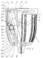
- a drill chuck 1 is shown that a Has chuck body 2, at the rear end of a Spindle receptacle 3 is formed, to which forward an axial passage 4 connects into a Tool holder 5 opens.
- this tool holder 5 continue to be axially inclined with respect to the chuck axis 6 in the chuck body 2 running recordings 7 for Clamping jaws 8 on their radially outer side each have a row of teeth 9 which in one Internal thread of a threaded ring 10 engage through a rotation of the threaded ring 10 relative to Chuck body 2 the jaws 8 in the To adjust guide receptacles 7 and so the drill chuck 1 to open or close.
- the threaded ring 10 with a coaxial adapter sleeve 11 coupled.
- the threaded ring 10 is axially rearward over a Pressure ring 12 supported against the chuck body 2, while the axial securing of the threaded ring 10 after is effected at the front via the clamping sleeve 11, which is a axially backward-pointing sleeve shoulder 13 and an axially backward biased Spring element 14 is held on the chuck body 2.
- the Spring element 14 is formed by an annular disc 15, which is attached axially from behind to the chuck body 2 is and by means of an in an annular groove 16 Collet 11 engaging on the washer 15th overlying circlip 17 the clamping sleeve 11 guaranteed.
- the pressure ring 12 is on an axially forward body shoulder 18 of the Support body 2 supported, a 25 percent Coverage of the pressure ring 12 by the body shoulder 18 he follows.
- the Dodge pressure ring 12 to the rear so that the Pressure ring 12 as an annular spring 19 with an axial spring action acts.
- the spring action of the pressure ring 12 is particularly pronounced due to the small number 25 percent coverage with the body shoulder 18, but the coverage can reach up to 70 percent can, if a correspondingly stiffer spring is desired.
- the deflection of the pressure ring 12 when the Clamping jaws 8 on the shank of the tool to be clamped corresponds to the axial distance of a sleeve collar 20 Adapter sleeve 11 from the chuck body 2 in the open state of the Drill chuck 1, so that when adjusting the Collet 11 with the threaded ring 10 together by the spring element 14 is supported, the clamping sleeve 11 so is widely adjusted that this on the chuck body 2 for System comes and therefore both damped and radial to be led.
- a large axial guide length of the Adapter sleeve 11 is given by the arrangement of the Sleeve collar 20 axially in front of the threaded ring 10 and in particular, as shown in Figure 1, by the Formation of the sleeve collar 20 by means of a radial inside collar 21 at the front end of the Adapter sleeve 11.
- Attenuator 22 arranged according to the Embodiment in Figure 1 and Figures 2 and 3 as Damping ring is formed.
- they show Embodiments in Figures 4 and 5 the realization of the damping song 22 by one of the sleeve collar 20th protruding damping leg 23, which is integral with the Sleeve collar 20 is formed by means of a Groove 24.
- Attenuator 22 is the Distance of the sleeve collar 20 from the chuck body 2 so dimensioned that the attenuator 22 is acted upon and a kind of clamping of the clamping sleeve 11 at its ends he follows.
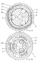
- the locking device 25 has a non-rotatably connected to the threaded ring 10 Intermediate sleeve 26 in which a locking member 27 is arranged which is due to the attacks (Fig. VII, VIIa) caused limited rotatability of the clamping sleeve 11th with respect to the threaded ring 10 when tightening (Fig. VIa) with a compared to the chuck body 2nd non-rotatable locking teeth 28 or when opening of the chuck 1 to be disengaged (Fig. VI).
- the locking toothing 28 is non-rotatable pressure ring 12 connected to the chuck body 2 trained, in principle also the possibility there is that the locking teeth 28 on the chuck body 2nd is formed if this is an axial extension has greater than the deflection of the pressure ring 12th during the tensioning process.
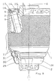
- Figure 8 shows an embodiment in which on the axially front end of the collet 11 a rotatable Protective cap 29 is arranged, which is a radially inward directed cap collar 30, which in one at the Adapter sleeve trained bearing groove 31 engages so that the Protective cap 29 in a simple orphan by plugging and Insert the cap collar 30 into the bearing groove 31 assemble. It is also possible to use cap collar 30 and Bearing groove 31 together, after plugging on the Protective cap 29 by pressure acting in the circumferential direction or train by roles.
Landscapes
- Engineering & Computer Science (AREA)
- Mechanical Engineering (AREA)
- Gripping On Spindles (AREA)
- Gears, Cams (AREA)
Abstract
Description
- Fig. 1
- eine Seitenansicht eines Bohrfutters einer ersten Ausfürungsform, links geschnitten dargestellt,
- Fig. 2
- eine der Figur 1 entsprechende Darstellung einer Ausführungsform mit Verriegelungsvorrichtung mit dem Druckring in der Ruhestellung,
- Fig. 3
- eine der Figur 2 entsprechende Darstellung mit dem ausgelenkten Druckring,
- Fig. 4
- eine der Figur 2 entsprechenden Darstellung einer alternativen Ausführungsform mit einem am Hülsenbund angeordneten Dämpfungsschenkel,
- Fig. 5
- eine der Figur 3 entsprechende Darstellung eines Bohrfutters gemäß Figur 4,
- Fig. 6
- der Schnitt VI - VI aus Figur 2,
- Fig. 6a
- der Schnitt VIa - VIa aus Fidur 2,
- Fig. 7
- der Schnitt VII - VII aus Figur 3,
- Fig. 7a
- der Schnitz VIIa - VIIa aus Figur 3, und
- Fig. 8
- eine Seitenansicht, teilweise geschnitten dargestellt, eines Bohrfutters mit einer drehbar auf der Spannhülse angeordneten Schutzkappe.
Claims (19)
- Bohrfutter, insbesondere zum Schlagbohren, mit einem an eine Bohrspindel anschließbaren Futterkörper (2), der geneigt zur Futterachse (6) verlaufende Führungsaufnahmen (7) für Spannbacken (8) aufweist, die zum Öffnen und Schließen des Bohrfutters (1) über eine Verzahnung (9) mit einem koaxial zur Futterachse (6) drehbaren Gewindering (10) in Eingriff stehen, zu dessen Betätigung eine koaxiale Spannhülse (11) vorgesehen ist, und mit einem der axial rückwärtigen Abstützung des Gewinderinges (10) gegenüber dem Futterkörper (2) dienenden Druckring (12), dadurch gekennzeichnet, daß der Druckring (12) als Ringfeder (19) mit axialer Federwirkung gestaltet ist, daß der Gewindering (12) axial nach vorn durch ein axial nach rückwärts vorgespanntes Federelement (14) gesichert ist, daß die Spannhülse (11) axial unverschieblich zu dem Gewindering (10) angeordnet ist, und daß beim Spannvorgang die Spannhülse (11) in Kontakt mit dem Futterkörper (2) bringbar ist.
- Bohrfutter nach Anspruch 1, dadurch gekennzeichnet, daß auf einer axial nach rückwärts gerichteten Hülsenschulter (13) der Spannhülse (11) der Gewindering (10) abgestützt und die Spannhülse (11) durch das Federelement (14) gegenüber dem Futterkörper (2) gehalten ist.
- Bohrfutter nach Anspruch 2, dadurch gekennzeichnet, daß das Federelement (14) durch eine Ringscheibe (15) gebildet ist.
- Bohrfutter nach Anspruch 3, dadurch gekennzeichnet, daß die Ringscheibe (15) axial von hinten auf den Futterkörper (2) aufsteckbar ist und mittels eines in eine Ringnut (16) der Spannhülse (11) eingreifenden, auf der Ringscheibe (15) aufliegenden Sicherungsringes (17) die Spannhülse (11) sichert.
- Bohrfutter nach einem der Ansprüche 1 bis 4, dadurch gekennzeichnet, daß der Druckring (12) an einer axial nach vorne gerichteten Körperschulter (18) des Futterkörpers (2) abgestützt ist bei maximal 70-prozentiger, vorzugsweise 50-prozentiger und insbesondere 25-prozentiger Überdeckung des Druckringes (12) durch die Körperschulter (18).
- Bohrfutter nach einem der Ansprüche 1 bis 5, dadurch gekennzeichnet, daß die Auslenkung des Druckringes (12) bei Anlage der Spannbacken (8) an den Schaft des zu spannenden Werkzeuges dem axialen Abstand eines Hülsenbundes (20) der Spannhülse (11) vom Futterkörper (2) im geöffneten Zustand des Bohrfutter (1) entspricht.
- Bohrfutter nach Anspruch 6, dadurch gekennzeichnet, daß der Hülsenbund (20) axial vor dem Gewindering (10) angeordnet ist.
- Bohrfutter nach Anspruch 7, dadurch gekennzeichnet, daß der Hülsenbund (20) durch einen radial nach innen gerichteten Kragen (21) am vorderen Ende der Spannhülse (11) gebildet ist.
- Bohrfutter nach einem der Ansprüche 6 bis 8, dadurch gekennzeichnet, daß zwischen dem Hülsenbund (20) und dem Futterkörper (2) ein Dämpfungsglied (22) angeordnet ist.
- Bohrfutter nach Anspruch 9, dadurch gekennzeichnet, daß das Dämpfungsglied (22) durch einen Dämpfungsring gebildet ist.
- Bohrfutter nach Anspruch 9, dadurch gekennzeichnet, daß das Dämpfungsglied (22) durch einen vom Hülsenbund (20) abstehenden Dämpfungsschenkel (23) gebildet ist.
- Bohrfutter nach Anspruch 11, dadurch gekennzeichnet, daß der Dämpfungsschenkel (23) einstückig mit dem Hülsenbund (20) gebildet und mittels einer in Umfangsrichtung verlaufenden Nut (24) realisiert ist.
- Bohrfutter nach einem der Ansprüche 2 bis 12, dadurch gekennzeichnet, daß der Gewindering (10) ungeteilt ausgebildet ist.
- Bohrfutter nach einem der Ansprüche 1 bis 13, dadurch gekennzeichnet, daß zwischen der Spannhülse (11) und dem Futterkörper (2) eine Verriegelungsvorrichtung (25) (25) angeordnet ist.
- Bohrfutter nach Anspruch 14, dadurch gekennzeichnet, daß die Verriegelungsvorrichtung (25) eine drehfest mit dem Gewindering (10) verbundene Zwischenhülse (26) aufweist, in der ein Sperrglied (27) angeordnet ist, das bei der durch Anschläge bewirkten begrenzten Verdrehbarkeit der Spannhülse (11) gegenüber dem Gewindering (10) Spannen in Eingriff mit einer gegenüber dem Futterkörper (2) undrehbaren Sperrverzahnung (28) bzw. beim Öffnen des Bohrfutters (1) außer Eingriff zu bringen ist.
- Bohrfutter nach Anspruch 15, dadurch gekennzeichnet, daß die Sperrverzahnung (28) an dem drehfest mit dem Futterkörper (2) verbundenen Druckring (12) ausgebildet ist.
- Bohrfutter nach Anspruch 15, dadurch gekennzeichnet, daß die Sperrverzahnung (28) am Futterkörper (2) ausgebildet ist und eine axiale Erstreckung aufweist, die größer als die Auslenkung des Druckringes (12) beim Spannvorgang ist.
- Bohrfutter nach einem der Ansprüche 1 bis 17, dadurch gekennzeichnet, daß auf der Spannhülse (11) eine drehbare Schutzkappe (29) angeordnet ist.
- Bohrfutter nach Anspruch 18, dadurch gekennzeichnet, daß die Schutzkappe (29) einen radial nach innen gerichteten Kappenbund (30) aufweist, der in eine an der Spannhülse (11) ausgebildete Lagernut (31) eingreift.
Applications Claiming Priority (2)
| Application Number | Priority Date | Filing Date | Title |
|---|---|---|---|
| DE10226429 | 2002-06-13 | ||
| DE10226429A DE10226429A1 (de) | 2002-06-13 | 2002-06-13 | Bohrfutter |
Publications (2)
| Publication Number | Publication Date |
|---|---|
| EP1371435A1 true EP1371435A1 (de) | 2003-12-17 |
| EP1371435B1 EP1371435B1 (de) | 2005-07-27 |
Family
ID=29557814
Family Applications (1)
| Application Number | Title | Priority Date | Filing Date |
|---|---|---|---|
| EP03011792A Expired - Lifetime EP1371435B1 (de) | 2002-06-13 | 2003-05-24 | Bohrfutter |
Country Status (4)
| Country | Link |
|---|---|
| US (1) | US6902172B2 (de) |
| EP (1) | EP1371435B1 (de) |
| CN (1) | CN100341650C (de) |
| DE (2) | DE10226429A1 (de) |
Cited By (2)
| Publication number | Priority date | Publication date | Assignee | Title |
|---|---|---|---|---|
| GB2410914A (en) * | 2004-02-14 | 2005-08-17 | Black & Decker Inc | Chuck |
| US7837200B2 (en) | 2005-07-01 | 2010-11-23 | Jacobs Chuck Manufacturing Company | Chuck |
Families Citing this family (21)
| Publication number | Priority date | Publication date | Assignee | Title |
|---|---|---|---|---|
| FR2847180B1 (fr) * | 2002-11-18 | 2005-02-11 | Amyot Ets Sa | Mandrin porte-outil a systeme de verrouillage |
| CN2582790Y (zh) * | 2002-11-25 | 2003-10-29 | 山东威达机械股份有限公司 | 自锁钻夹头 |
| US20050087937A1 (en) * | 2003-10-22 | 2005-04-28 | Wenhua Zhou | Lock type manually tightened chuck |
| GB2408707A (en) * | 2003-12-04 | 2005-06-08 | Black & Decker Inc | Chuck |
| CN2715890Y (zh) * | 2004-08-03 | 2005-08-10 | 山东威达机械股份有限公司 | 带响自锁式钻夹头 |
| USD529522S1 (en) * | 2004-08-09 | 2006-10-03 | Jacobs Chuck Manufacturing Company | Chuck sleeve |
| WO2006099820A1 (de) * | 2005-03-19 | 2006-09-28 | Röhm Gmbh | Bohrfutter |
| US7472913B2 (en) * | 2005-06-09 | 2009-01-06 | Jacobs Chuck Manufacturing Company | Drill chuck |
| US7637510B2 (en) * | 2005-10-12 | 2009-12-29 | Shandong Weida Machinery Company Limited | Chuck with gripping mechanism stop |
| USD532271S1 (en) * | 2005-10-20 | 2006-11-21 | Jacobs Chuck Manufacturing Company | Drill chuck |
| USD533425S1 (en) * | 2005-10-20 | 2006-12-12 | Jacobs Chuck Manufacturing Company | Drill chuck sleeve |
| DE102006011344A1 (de) * | 2006-03-11 | 2007-09-13 | Röhm Gmbh | Bohrfutter |
| USD563187S1 (en) * | 2007-02-26 | 2008-03-04 | Zhenqian Hu | Drill chuck |
| USD587978S1 (en) * | 2007-03-28 | 2009-03-10 | Robert Bosch Gmbh | Right angle attachment for rotary tool |
| US8777232B2 (en) | 2009-07-29 | 2014-07-15 | Jacobs Chuck Manufacturing Company | Self-tightening chuck with a radial lock |
| DE102015102241B4 (de) * | 2015-02-17 | 2024-10-02 | Röhm Gmbh | Bohrfutter |
| CN105784413A (zh) * | 2016-04-27 | 2016-07-20 | 镇江市建科工程质量检测中心有限公司 | 外墙节能检测用钻芯机 |
| WO2018068284A1 (en) | 2016-10-14 | 2018-04-19 | Jacobs Chuck Manufacturing (Suzhou) Company, Ltd. | Chuck with slip protection |
| CN111163888B (zh) * | 2017-07-28 | 2021-12-10 | 捷可勃斯夹头制造(苏州)有限公司 | 具有抗振特征的锁定夹头 |
| WO2020243878A1 (en) * | 2019-06-03 | 2020-12-10 | Jacobs Chuck Manufactuirng (Suzhou) Company, Ltd. | Chuck with locking clutch |
| DE102020131833A1 (de) * | 2020-12-01 | 2022-06-02 | Röhm Gmbh | Bohrfutter |
Citations (5)
| Publication number | Priority date | Publication date | Assignee | Title |
|---|---|---|---|---|
| EP0325284A2 (de) * | 1988-01-20 | 1989-07-26 | The Jacobs Manufacturing Company | Bohrfutter ohne Schlüssel |
| EP0519412A2 (de) * | 1991-06-21 | 1992-12-23 | Jacobs Chuck Technology Corporation | Schlagwerkzeughalter |
| US5732956A (en) * | 1989-12-11 | 1998-03-31 | Power Tool Holders Incorporated | Non impact keyless chuck |
| US6260857B1 (en) * | 1999-01-06 | 2001-07-17 | James L. Wienhold | Quick-change three-jaw drill chuck |
| US20020022442A1 (en) * | 2000-08-10 | 2002-02-21 | Rohm Gmbh | Drill chuck with cushioned tightening ring |
Family Cites Families (15)
| Publication number | Priority date | Publication date | Assignee | Title |
|---|---|---|---|---|
| DE8436752U1 (de) * | 1984-12-15 | 1985-03-21 | Röhm, Günter Horst, 7927 Sontheim | Bohrfutter |
| JPH047843Y2 (de) * | 1987-11-09 | 1992-02-28 | ||
| DE4023303C1 (de) * | 1990-07-21 | 1991-09-26 | Guenter Horst 7927 Sontheim De Roehm | |
| ES2055463T3 (es) * | 1990-07-21 | 1994-08-16 | Roehm Guenter H | Portabrocas. |
| BR9304703A (pt) * | 1992-11-14 | 1994-05-17 | Roehm Guenter H | Mandril para brocas |
| US5503409A (en) * | 1993-12-15 | 1996-04-02 | Roehm; Guenter | Self-tightening hammer-drill chuck |
| DE4438991C5 (de) * | 1994-10-31 | 2009-07-30 | Röhm Gmbh | Bohrfutter |
| EP0785041B1 (de) * | 1996-01-17 | 2001-02-28 | Röhm GmbH | Bohrfutter |
| US5816583A (en) * | 1996-12-04 | 1998-10-06 | Power Tool Holders, Inc. | Integral locking sleeve chuck |
| DE19829251B4 (de) * | 1998-01-14 | 2008-05-21 | Röhm Gmbh | Bohrvorrichtung |
| DE19802080B4 (de) * | 1998-01-21 | 2008-07-03 | Röhm Gmbh | Bohrfutter |
| DE19805019B4 (de) * | 1998-02-07 | 2008-04-03 | Röhm Gmbh | Bohrfutter |
| EP1170079B2 (de) * | 2000-07-03 | 2010-10-06 | Röhm GmbH | Bohrfutter |
| DE10106251B4 (de) * | 2001-02-10 | 2005-07-28 | Röhm Gmbh | Bohrfutter |
| US6860488B2 (en) * | 2001-10-10 | 2005-03-01 | Rohm Gmbh | Drill chuck with front-end shield |
-
2002
- 2002-06-13 DE DE10226429A patent/DE10226429A1/de not_active Withdrawn
-
2003
- 2003-05-24 EP EP03011792A patent/EP1371435B1/de not_active Expired - Lifetime
- 2003-05-24 DE DE50300841T patent/DE50300841D1/de not_active Expired - Lifetime
- 2003-06-10 US US10/457,870 patent/US6902172B2/en not_active Expired - Fee Related
- 2003-06-13 CN CNB031586953A patent/CN100341650C/zh not_active Expired - Fee Related
Patent Citations (5)
| Publication number | Priority date | Publication date | Assignee | Title |
|---|---|---|---|---|
| EP0325284A2 (de) * | 1988-01-20 | 1989-07-26 | The Jacobs Manufacturing Company | Bohrfutter ohne Schlüssel |
| US5732956A (en) * | 1989-12-11 | 1998-03-31 | Power Tool Holders Incorporated | Non impact keyless chuck |
| EP0519412A2 (de) * | 1991-06-21 | 1992-12-23 | Jacobs Chuck Technology Corporation | Schlagwerkzeughalter |
| US6260857B1 (en) * | 1999-01-06 | 2001-07-17 | James L. Wienhold | Quick-change three-jaw drill chuck |
| US20020022442A1 (en) * | 2000-08-10 | 2002-02-21 | Rohm Gmbh | Drill chuck with cushioned tightening ring |
Cited By (7)
| Publication number | Priority date | Publication date | Assignee | Title |
|---|---|---|---|---|
| GB2410914A (en) * | 2004-02-14 | 2005-08-17 | Black & Decker Inc | Chuck |
| GB2410914B (en) * | 2004-02-14 | 2008-07-30 | Black & Decker Inc | Chuck |
| US7837200B2 (en) | 2005-07-01 | 2010-11-23 | Jacobs Chuck Manufacturing Company | Chuck |
| US8029000B2 (en) | 2005-07-01 | 2011-10-04 | Jacobs Chuck Manufacturing Company | Chuck |
| US8387995B2 (en) | 2005-07-01 | 2013-03-05 | Jacobs Chuck Manufacturing Company | Chuck |
| US8777231B2 (en) | 2005-07-01 | 2014-07-15 | Apex Brands, Inc. | Chuck |
| US9358617B2 (en) | 2005-07-01 | 2016-06-07 | Apex Brands, Inc. | Chuck |
Also Published As
| Publication number | Publication date |
|---|---|
| US6902172B2 (en) | 2005-06-07 |
| CN1494970A (zh) | 2004-05-12 |
| DE50300841D1 (de) | 2005-09-01 |
| EP1371435B1 (de) | 2005-07-27 |
| US20040032095A1 (en) | 2004-02-19 |
| CN100341650C (zh) | 2007-10-10 |
| HK1064322A1 (zh) | 2005-01-28 |
| DE10226429A1 (de) | 2003-12-24 |
Similar Documents
| Publication | Publication Date | Title |
|---|---|---|
| EP1371435B1 (de) | Bohrfutter | |
| EP1504836B1 (de) | Schnellspannbohrfutter | |
| EP2599568B1 (de) | Bohrvorrichtung | |
| EP0710518B1 (de) | Bohrfutter | |
| DE4445858B4 (de) | Bohrvorrichtung | |
| DE10106251B4 (de) | Bohrfutter | |
| DE102009044049A1 (de) | Spannzangenfutter | |
| EP1029621A1 (de) | Bohrfutter | |
| EP0131069B1 (de) | Walzwerkzeug | |
| DE4233712A1 (de) | Kraftangetriebenes Elektrohandwerkzeug | |
| DE19805019B4 (de) | Bohrfutter | |
| EP0245629A2 (de) | Spanneinrichtung an Drehspindeln von Drehmaschinen für kraftbetätigte Werkstückhalter, insbesondere Spannfutter | |
| DE102005008892A1 (de) | Spannvorrichtung | |
| DE19710565C1 (de) | Bohrfutter | |
| DE102005048167B4 (de) | Bohrfutter | |
| DE10008297B4 (de) | Fahrzeug | |
| EP1170078A1 (de) | Bohrfutter mit einer eine Steuerkurve aufweisenden Spannhülse | |
| DE19716813A1 (de) | Taumelgelenkbeschlag für Kraftfahrzeugsitze, insbesondere für Rückenlehnengelenke | |
| DE102004004458A1 (de) | Bohrfutter | |
| DE9011075U1 (de) | Schrauber | |
| DE10237750A1 (de) | Bohrfutter | |
| DE9208471U1 (de) | Schraubendreheraufsatz zum Befestigen an einer Bohrmaschine | |
| WO2020094541A1 (de) | Gurtwellengehäuse, gurtwelle, gurtstraffer und verfahren zur montage eines gurtstraffers |
Legal Events
| Date | Code | Title | Description |
|---|---|---|---|
| PUAI | Public reference made under article 153(3) epc to a published international application that has entered the european phase |
Free format text: ORIGINAL CODE: 0009012 |
|
| 17P | Request for examination filed |
Effective date: 20031018 |
|
| AK | Designated contracting states |
Kind code of ref document: A1 Designated state(s): AT BE BG CH CY CZ DE DK EE ES FI FR GB GR HU IE IT LI LU MC NL PT RO SE SI SK TR |
|
| AX | Request for extension of the european patent |
Extension state: AL LT LV MK |
|
| 17Q | First examination report despatched |
Effective date: 20040414 |
|
| AKX | Designation fees paid |
Designated state(s): CZ DE ES FR GB |
|
| GRAP | Despatch of communication of intention to grant a patent |
Free format text: ORIGINAL CODE: EPIDOSNIGR1 |
|
| GRAS | Grant fee paid |
Free format text: ORIGINAL CODE: EPIDOSNIGR3 |
|
| GRAA | (expected) grant |
Free format text: ORIGINAL CODE: 0009210 |
|
| AK | Designated contracting states |
Kind code of ref document: B1 Designated state(s): CZ DE ES FR GB |
|
| PG25 | Lapsed in a contracting state [announced via postgrant information from national office to epo] |
Ref country code: GB Free format text: LAPSE BECAUSE OF FAILURE TO SUBMIT A TRANSLATION OF THE DESCRIPTION OR TO PAY THE FEE WITHIN THE PRESCRIBED TIME-LIMIT Effective date: 20050727 Ref country code: CZ Free format text: LAPSE BECAUSE OF FAILURE TO SUBMIT A TRANSLATION OF THE DESCRIPTION OR TO PAY THE FEE WITHIN THE PRESCRIBED TIME-LIMIT Effective date: 20050727 |
|
| REG | Reference to a national code |
Ref country code: GB Ref legal event code: FG4D Free format text: NOT ENGLISH |
|
| REF | Corresponds to: |
Ref document number: 50300841 Country of ref document: DE Date of ref document: 20050901 Kind code of ref document: P |
|
| GBV | Gb: ep patent (uk) treated as always having been void in accordance with gb section 77(7)/1977 [no translation filed] |
Effective date: 20050727 |
|
| ET | Fr: translation filed | ||
| PLBE | No opposition filed within time limit |
Free format text: ORIGINAL CODE: 0009261 |
|
| STAA | Information on the status of an ep patent application or granted ep patent |
Free format text: STATUS: NO OPPOSITION FILED WITHIN TIME LIMIT |
|
| 26N | No opposition filed |
Effective date: 20060428 |
|
| PG25 | Lapsed in a contracting state [announced via postgrant information from national office to epo] |
Ref country code: ES Free format text: LAPSE BECAUSE OF NON-PAYMENT OF DUE FEES Effective date: 20060531 |
|
| PGFP | Annual fee paid to national office [announced via postgrant information from national office to epo] |
Ref country code: DE Payment date: 20130311 Year of fee payment: 11 |
|
| PGFP | Annual fee paid to national office [announced via postgrant information from national office to epo] |
Ref country code: FR Payment date: 20130604 Year of fee payment: 11 |
|
| REG | Reference to a national code |
Ref country code: DE Ref legal event code: R119 Ref document number: 50300841 Country of ref document: DE |
|
| REG | Reference to a national code |
Ref country code: DE Ref legal event code: R119 Ref document number: 50300841 Country of ref document: DE Effective date: 20141202 |
|
| REG | Reference to a national code |
Ref country code: FR Ref legal event code: ST Effective date: 20150130 |
|
| PG25 | Lapsed in a contracting state [announced via postgrant information from national office to epo] |
Ref country code: DE Free format text: LAPSE BECAUSE OF NON-PAYMENT OF DUE FEES Effective date: 20141202 |
|
| PG25 | Lapsed in a contracting state [announced via postgrant information from national office to epo] |
Ref country code: FR Free format text: LAPSE BECAUSE OF NON-PAYMENT OF DUE FEES Effective date: 20140602 |