EP1369879A2 - Hochdruckdurchführungen an isolierenden Bestandteilen von Druckgefässwandungen - Google Patents
Hochdruckdurchführungen an isolierenden Bestandteilen von Druckgefässwandungen Download PDFInfo
- Publication number
- EP1369879A2 EP1369879A2 EP03011877A EP03011877A EP1369879A2 EP 1369879 A2 EP1369879 A2 EP 1369879A2 EP 03011877 A EP03011877 A EP 03011877A EP 03011877 A EP03011877 A EP 03011877A EP 1369879 A2 EP1369879 A2 EP 1369879A2
- Authority
- EP
- European Patent Office
- Prior art keywords
- insulating body
- pressure
- pressure vessel
- vessel wall
- conical
- Prior art date
- Legal status (The legal status is an assumption and is not a legal conclusion. Google has not performed a legal analysis and makes no representation as to the accuracy of the status listed.)
- Granted
Links
Images
Classifications
-
- H—ELECTRICITY
- H01—ELECTRIC ELEMENTS
- H01B—CABLES; CONDUCTORS; INSULATORS; SELECTION OF MATERIALS FOR THEIR CONDUCTIVE, INSULATING OR DIELECTRIC PROPERTIES
- H01B17/00—Insulators or insulating bodies characterised by their form
- H01B17/26—Lead-in insulators; Lead-through insulators
- H01B17/30—Sealing
- H01B17/303—Sealing of leads to lead-through insulators
- H01B17/305—Sealing of leads to lead-through insulators by embedding in glass or ceramic material
-
- H—ELECTRICITY
- H01—ELECTRIC ELEMENTS
- H01B—CABLES; CONDUCTORS; INSULATORS; SELECTION OF MATERIALS FOR THEIR CONDUCTIVE, INSULATING OR DIELECTRIC PROPERTIES
- H01B17/00—Insulators or insulating bodies characterised by their form
- H01B17/26—Lead-in insulators; Lead-through insulators
- H01B17/30—Sealing
- H01B17/301—Sealing of insulators to support
Definitions
- the invention relates to electrical bushings on insulating Components of a pressure vessel wall, in particular for housings from Pressure sensors and a method for their production.
- US-A-4 816 621 describes a ceramic-metal bushing Gold solder connection, which is used for implantable cardiac pacemakers or Nerve stimulators are provided for high pressure application, however is unsuitable.
- JP 59 078 983 "Ceramic and metal joint mechanism" conical rotor-shaft connection described.
- the invention is based, a method and a task Specify device of the type mentioned, in which an increased Pressure resistance is guaranteed and only a small drop in Temperature increase occurs.
- the object is achieved by methods which and 8 specified features and with an arrangement which the in Contains specified features, solved.
- a truncated cone-shaped insulating body which sits in a conical receptacle under high radial compressive stress, withstands high pneumatic or hydraulic working pressures on its base.
- a high material pressure resistance (from 200 MPa) of the insulating body ensures the pressure resistance of the bushing.
- the resistance of the lead-through conductors inserted into the insulating body to thermal and mechanical load changes is achieved by using material with a high modulus of elasticity, which is significantly higher than that of metals and greater than 250 GPa.
- insulating bodies made of high-strength Al 2 O 3 ceramic which fulfills the aforementioned material properties, has a half cone angle of 2-4 ° and is fastened in the lead-through conductor with hard solder.
- the required radial compressive stress can be achieved by shrinking on, by preheating a conical holder made of high-strength steel by 200 to 300 K compared to the ambient temperature and inserting the insulating body, which remains at ambient temperature, into the conical holder under slight pressure. After the temperature equalization, the insulating body is under radial compressive stress, which increases due to the effect of the cone angle when the working pressure is applied.
- An advantageous embodiment of the arrangement according to the invention arises in that when soldering lead-through conductors, in particular from Feed-through wires with a maximum diameter of 0.8 mm, the ceramic insulating body is provided with stepped through holes, with the larger diameter of the through holes on the high pressure side is arranged, and the lead-through wires a reinforced middle part own, this middle part after soldering in at the level of remote through hole.
- Feed-through conductors especially for feed-through pins with a Diameter of at least 1.0 mm
- conical Through holes of the insulator have through holes that are half Have a cone angle of 4 - 8 °.
- the cone angle opens after the High pressure side.
- Feedthrough pins are also in this cone conical middle part arranged firmly, the cone angle equal to or around 0.5 - 1 ° smaller than the cone angle of the through holes.
- the feed-through pins are inserted in that the Remaining feed-through pins in the conical Through holes are inserted at a time when the Insulator is essentially the temperature of the conical receptacle but has not yet approximated the ambient temperature.
- the ceramic insulating body with its internal and external metal partners, i.e. the Implementation pins or the conical receptacle
- the Implement pins at least on their middle part and / or the Pressure vessel wall at least in its conical receptacle with a ductile metallic coating.
- This can be done, for example a galvanically applied copper layer of 5 - 20 ⁇ m, which by annealing was homogenized at 950 - 1000 ° C, are used.
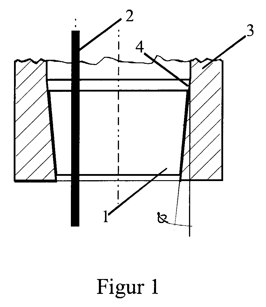
- FIG. 1 shows a section through a bushing arrangement.
- a conical receptacle 4 made of stainless steel is located in a pressure vessel wall 3.
- the receptacle 4 has an outer diameter of 16 mm.
- a conical insulating body 1 made of high-strength Al 2 O 3 ceramic with a height of 5 mm, an average diameter of 8 mm and a half cone angle of 3 °, in which a lead-through conductor 2 is hard soldered.
- the receptacle 4 is shrunk onto the insulating body 1. It could be demonstrated experimentally that the procedure thus produced has a pressure resistance of more than 4000 bar at a temperature of 400 ° C.
- FIG. 2 explains various fastening options for the arrangement of the feed-through conductor 2 in the conical insulating body 1.
- a conical through hole 5 with a half cone angle of 5 ° is made in the conical insulating body 1.
- a bushing pin 6 fastened by shrinking on, with a conical central part 7, which has an average diameter of 1.2 mm and a half cone angle of 4.5 °.
- the conical insulating body 1 is included a stepped through hole 9, in which a grommet 10 is introduced with a reinforced central part 11.
- the through hole 9 is with with a diameter of 0.5 mm and a heel of Diameter 1.0 mm and a height of 1.5 mm.
- the Feed-through wires 10 have a diameter of 0.45 mm and are with a reinforced middle part 11 with a diameter of 0.8 mm and with a height of 0.3 mm. You are using a copper silver solder that has a 10% titanium content, hard soldered into the insulating body 1.
- the sectional view shown in FIG. 3 shows a section of a pressure vessel wall 3 with a conical receptacle 4.
- the receptacle 4 contains the conical insulating body 1 shown in half section, which in turn is provided with a conical through-hole in which there is a conical middle part 7 provided through pin 6 is attached.
- both the outer surface of the conical middle part 7 of the lead-through pin 6 and the inner surface of the conical receptacle 4 of the pressure vessel wall 3 are provided with ductile metallic coatings 8.
- a galvanically applied and homogenized copper layer of approx. 10 ⁇ m thickness is applied here as the ductile metallic coating 8.
- the conical insulating body 1 is connected via the ductile metallic coatings 8 to the vessel wall 3 or the bushing pins 6 by shrinking on. The arrangement thus forms a hermetic, pressure and temperature-resistant bushing.
Landscapes
- Chemical & Material Sciences (AREA)
- Engineering & Computer Science (AREA)
- Ceramic Engineering (AREA)
- Connections Arranged To Contact A Plurality Of Conductors (AREA)
- Filling Or Discharging Of Gas Storage Vessels (AREA)
- Insulators (AREA)
- Chemical Vapour Deposition (AREA)
- Electron Sources, Ion Sources (AREA)
Abstract
Description
Besonders vorteilhaft ist es, Isolierkörper aus hochfester Al2O3-Keramik zu verwenden, der die vorgenannten Materialeigenschaften erfüllt, einen halben Konuswinkel von 2 - 4° aufweist und in dem Durchführungsleiter mit Hartlot befestigt sind. Die erforderliche radiale Druckspannung kann durch Aufschrumpfen erreicht werden, indem eine konische Aufnahme aus hochfestem Stahl um 200 bis 300 K gegenüber Umgebungstemperatur vorgewärmt und der auf Umgebungstemperatur verbliebene Isolierkörper unter leichtem Druck in die konische Aufnahme eingesetzt wird. Nach dem Temperaturausgleich steht der Isolierkörper unter radialer Druckspannung, die sich infolge der Wirkung des Konuswinkels bei Anliegen des Arbeitsdruckes noch verstärkt. Damit ergibt sich zwischen dem Isolierkörper und der konischen Aufnahme eine hermetische Verbindung, die auch bei erhöhten Temperaturen hohen Arbeitsdrücken Stand hält. Dabei ist es vorteilhaft, das Hartlot zur Befestigung von Durchführungsleitern in den Durchgangslöchern des keramischen Isolierkörpers mit einem Titangehalt von 3-12% zu versehen und Al2O3-Keramik zu verwenden, die eine Glasphase von ca. 0,5% besitzt.
- Figur 1
- einen Schnitt durch eine Anordnung, bei der ein konischer Isolierkörper in einer konischen Aufnahme sitzt,
- Figur 2
- einen Schnitt durch den konischen Isolierkörper, der
konische und abgesetzte Durchgangslöcher aufweist,
und - Figur 3
- einen Schnitt einer Durchführung mit duktilen metallischen Beschichtungen.
In der links dargestellten Anordnung ist im konischen Isolierkörper 1 ein konisches Durchgangsloch 5 mit einem halben Konuswinkel von 5° angebracht. In diesem befindet sich ein durch Aufschrumpfen befestigter Durchführungsstift 6 mit konischem Mittelteil 7, das einen mittleren Durchmesser von 1,2 mm und einem halben Konuswinkel von 4,5° aufweist.
- 1
- konischer Isolierkörper
- 2
- Durchführungsleiter
- 3
- Druckgefäßwandung
- 4
- konische Aufnahme
- 5
- konisches Durchgangsloch
- 6
- Durchführungsstift
- 7
- konisches Mittelteil
- 8
- duktile metallische Beschichtung
- 9
- abgesetztes Durchgangsloch
- 10
- Durchführungsdraht
- 11
- verstärktes Mittelteil
- α
- Konuswinkel
Claims (8)
- Elektrische Durchführung an isolierenden Bestandteilen einer Druckgefäßwandung (3), insbesondere für Gehäuse von Drucksensoren, dadurch gekennzeichnet, dass die Druckgefäßwandung (3) eine konische Aufnahme (4) aufweist, in die ein außen konischer Isolierkörper (1), in dem ein oder mehrere elektrisch leitende Durchführungsleiter (2) fest angeordnet sind, eingesetzt ist; wobei die Konuswinkel der Aufnahme (4) und des Isolierkörpers (1) sich nach der zur Hochdruckseite hin öffnen.
- Durchführung nach Anspruch 1, dadurch gekennzeichnet, dass der konische Isolierkörper (1) aus hochfester Al2O3-Keramik besteht, einen halben Konuswinkel von 2 - 4° aufweist und die Durchführungen (2) mit Hartlot im Isolierkörper (1) befestigt sind.
- Durchführung nach Anspruch 1 oder 2, dadurch gekennzeichnet, dass die hochfeste Al2O3-Keramik des Isolierkörpers (1) eine Glasphase von ca. 0,5% besitzt und das Hartlot zur Befestigung der Durchführungen (2) einen Bestandteil von 8-12 Gewichts- % an Titan enthält.
- Durchführung nach einem der vorhergehenden Ansprüche, dadurch gekennzeichnet, dass in dem Isolierkörper (1) aus hochfester Al2O3-Keramik konische Durchgangslöcher (5) mit einem halben Konuswinkel von 4 - 8°, der sich nach der Hochdruckseite hin öffnet, und in den Durchgangslöchern (5) Durchführungsstifte (6), die ein konisches Mittelteil (7) aufweisen, dessen Konuswinkel gleich dem oder um 0,5 - 1° kleiner als der Konuswinkel der Durchgangslöcher (5) ist, haftfest angeordnet sind.
- Durchführung nach einem der vorhergehenden Ansprüche, dadurch gekennzeichnet, dass die Durchführungsstifte (6) mindestens auf Ihrem Mittelteil und/oder die Druckgefäßwandung (3) mindestens in ihrer konischen Aufnahme (4) eine duktile metallische Beschichtung (8) aufweisen.
- Durchführung nach einem der Ansprüche 2 bis 5, dadurch gekennzeichnet, dass in dem Isolierkörper (1) aus hochfester Al2O3-Keramik abgesetzte Durchgangslöcher (9) mit einem größeren Durchmesser auf der Hochdruckseite, und in diesen Durchgangslöchern (9) Durchgangsdrähte (10) mit einem verstärktem Mittelteil (11) haftfest angeordnet sind.
- Verfahren zur Herstellung einer Durchführung nach einem der Ansprüche 1 bis 6, dadurch gekennzeichnet, dass die Druckgefäßwandung (3) zunächst um 200 bis 300 K gegenüber Umgebungstemperatur aufgeheizt und danach der Isolierkörper (1) in die Druckgefäßwandung (3) unter leichten Druck eingesetzt und nach Durchwärmung des Isolierkörpers (1) die Durchführungsstifte (6) in diesen eingepresst werden.
- Verfahren zur Herstellung einer Durchführung nach Anspruch 7, dadurch gekennzeichnet, dass für die Durchführungsstifte (6) und/oder die Druckgefäßwandung (3), eine metallischen Beschichtung (8) galvanisch aufgetragen wird, und danach die beschichteten Durchführungsstifte (6) und/oder die Druckgefäßwandung (3) durch Glühen unter Wasserstoff bei einer Temperatur, die um 50 - 100 K unter dem Schmelzpunkt der Beschichtung liegt, homogenisiert werden.
Applications Claiming Priority (2)
| Application Number | Priority Date | Filing Date | Title |
|---|---|---|---|
| DE10225318 | 2002-06-06 | ||
| DE10225318 | 2002-06-06 |
Publications (3)
| Publication Number | Publication Date |
|---|---|
| EP1369879A2 true EP1369879A2 (de) | 2003-12-10 |
| EP1369879A3 EP1369879A3 (de) | 2004-01-21 |
| EP1369879B1 EP1369879B1 (de) | 2007-08-29 |
Family
ID=29432693
Family Applications (1)
| Application Number | Title | Priority Date | Filing Date |
|---|---|---|---|
| EP03011877A Expired - Lifetime EP1369879B1 (de) | 2002-06-06 | 2003-05-27 | Hochdruckdurchführungen an isolierenden Bestandteilen von Druckgefässwandungen |
Country Status (3)
| Country | Link |
|---|---|
| EP (1) | EP1369879B1 (de) |
| AT (1) | ATE371935T1 (de) |
| DE (2) | DE50308046D1 (de) |
Cited By (1)
| Publication number | Priority date | Publication date | Assignee | Title |
|---|---|---|---|---|
| DE102014202687A1 (de) * | 2014-02-14 | 2015-08-20 | Robert Bosch Gmbh | Kraftstoffeinspritzsystem |
Families Citing this family (2)
| Publication number | Priority date | Publication date | Assignee | Title |
|---|---|---|---|---|
| DE102010048903B4 (de) * | 2010-10-08 | 2014-10-30 | Hydac Electronic Gmbh | Elektrische Durchführung für Hochdruckanwendungen als Träger für Sensoren |
| EP2579013A1 (de) | 2011-10-07 | 2013-04-10 | Technische Universität Darmstadt | Erfindung betreffend druckbeaufschlagte Stromdurchführungen |
Family Cites Families (3)
| Publication number | Priority date | Publication date | Assignee | Title |
|---|---|---|---|---|
| US3173992A (en) * | 1962-11-16 | 1965-03-16 | Technical Drilling Service Inc | Resilient, high temperature resistant multiple conductor seal for conical ports |
| US4519662A (en) * | 1982-04-08 | 1985-05-28 | Westinghouse Electric Corp. | High pressure electrical penetrator |
| DE3720061A1 (de) * | 1987-06-16 | 1988-12-29 | Philips Patentverwaltung | Stromdurchfuehrung fuer hochdruckbehaelter mit innendruecken groesser als 1.000 bar |
-
2003
- 2003-05-27 DE DE50308046T patent/DE50308046D1/de not_active Expired - Lifetime
- 2003-05-27 AT AT03011877T patent/ATE371935T1/de active
- 2003-05-27 DE DE10323945A patent/DE10323945A1/de not_active Withdrawn
- 2003-05-27 EP EP03011877A patent/EP1369879B1/de not_active Expired - Lifetime
Cited By (1)
| Publication number | Priority date | Publication date | Assignee | Title |
|---|---|---|---|---|
| DE102014202687A1 (de) * | 2014-02-14 | 2015-08-20 | Robert Bosch Gmbh | Kraftstoffeinspritzsystem |
Also Published As
| Publication number | Publication date |
|---|---|
| DE50308046D1 (de) | 2007-10-11 |
| DE10323945A1 (de) | 2004-04-08 |
| ATE371935T1 (de) | 2007-09-15 |
| EP1369879A3 (de) | 2004-01-21 |
| EP1369879B1 (de) | 2007-08-29 |
Similar Documents
| Publication | Publication Date | Title |
|---|---|---|
| DE60005118T2 (de) | Durchführvorrichtungen | |
| EP0414872B1 (de) | Elektrisch leitende durchführung und verfahren zu ihrer herstellung | |
| DE19819797C2 (de) | Durchführungsbaugruppe für eine implantierbare medizinische Vorrichtung | |
| EP0269007A1 (de) | Keramik-Metall-Durchführung, insbesondere für Nerven- oder Herzschrittmacher, und Verfahren zu deren Herstellung | |
| DE102009035972A1 (de) | Cermethaltige Durchführung für eine medizinisch implantierbare Vorrichtung | |
| EP3277504A2 (de) | Verfahren zur herstellung mindestens eines federkontaktstifts oder einer federkontaktstift-anordnung sowie entsprechende vorrichtungen | |
| DE102019208035B4 (de) | Glas-Metall-Durchführung mit einer Hülse | |
| EP2371419A2 (de) | Elektrische Durchführung eines Kondensators für medizinische Implantate sowie Verfahren zur Herstellung und Verwendung einer solchen | |
| WO2010133402A1 (de) | Keramisches bauteil mit mindestens einer elektrischen durchführung, verfahren zu dessen herstellung und drucksensor mit einem solchen bauteil | |
| DE10029004C2 (de) | Keramikheizungs-Glühkerze | |
| EP0248977A1 (de) | Elektrisches Anzündelement und Verfahren zu seiner Herstellung | |
| DE3311507C2 (de) | Zuführanordnung für ein Humanimplantat und Verfahren zu deren Herstellung | |
| EP2965783B1 (de) | Verfahren zur herstellung eines stifts für eine durchführung eines elektromedizinischen implantats und einer durchführung | |
| EP1369879B1 (de) | Hochdruckdurchführungen an isolierenden Bestandteilen von Druckgefässwandungen | |
| EP3072553B1 (de) | Anschlussstift und durchführung | |
| EP3069760B1 (de) | Implantierbare elektromedizinische vorrichtung | |
| EP3332836B1 (de) | Durchführung eines implantierbaren medizinelektronischen geräts | |
| DE102004024920B4 (de) | Drucksensor | |
| DE69409334T2 (de) | Verfahren zur Verbindung einer Molybdän Folie mit einem Teil eines Molybdän Leiters und Herstellungsmethode eines hermetisch eingeschossenen Lampenteils unter Verwendung dieses Verfahrens | |
| DE102011003397B4 (de) | Glas-Titan-Dichtung und Verfahren zur Herstellung einer Glas-Titan-Dichtung | |
| EP3181194A1 (de) | Durchführung eines medizinelektronischen geräts, verfahren zur herstellung einer solchen und medizinelektronisches gerät | |
| DE102009014282B4 (de) | Vorrichtung, aufweisend mindestens zwei miteinander verbundene Teile aus Metall | |
| DE102020215508A1 (de) | Durchführung, umfassend Zwischenverbindungs-Kontaktstellen | |
| EP3311883B1 (de) | Anschlussstift und durchführung | |
| DE10248045B4 (de) | Glühkerze |
Legal Events
| Date | Code | Title | Description |
|---|---|---|---|
| PUAI | Public reference made under article 153(3) epc to a published international application that has entered the european phase |
Free format text: ORIGINAL CODE: 0009012 |
|
| PUAL | Search report despatched |
Free format text: ORIGINAL CODE: 0009013 |
|
| AK | Designated contracting states |
Kind code of ref document: A2 Designated state(s): AT BE BG CH CY CZ DE DK EE ES FI FR GB GR HU IE IT LI LU MC NL PT RO SE SI SK TR |
|
| AX | Request for extension of the european patent |
Extension state: AL LT LV MK |
|
| AK | Designated contracting states |
Kind code of ref document: A3 Designated state(s): AT BE BG CH CY CZ DE DK EE ES FI FR GB GR HU IE IT LI LU MC NL PT RO SE SI SK TR |
|
| AX | Request for extension of the european patent |
Extension state: AL LT LV MK |
|
| RIC1 | Information provided on ipc code assigned before grant |
Ipc: 7H 01B 17/30 A |
|
| 17P | Request for examination filed |
Effective date: 20040720 |
|
| D17P | Request for examination filed (deleted) | ||
| AKX | Designation fees paid | ||
| R17P | Request for examination filed (corrected) |
Effective date: 20040825 |
|
| RBV | Designated contracting states (corrected) |
Designated state(s): AT BE BG CH CY CZ DE DK EE ES FI FR GB GR HU IE IT LI LU MC NL PT RO SE SI SK TR |
|
| REG | Reference to a national code |
Ref country code: DE Ref legal event code: 8566 |
|
| GRAP | Despatch of communication of intention to grant a patent |
Free format text: ORIGINAL CODE: EPIDOSNIGR1 |
|
| GRAS | Grant fee paid |
Free format text: ORIGINAL CODE: EPIDOSNIGR3 |
|
| GRAA | (expected) grant |
Free format text: ORIGINAL CODE: 0009210 |
|
| AK | Designated contracting states |
Kind code of ref document: B1 Designated state(s): AT BE BG CH CY CZ DE DK EE ES FI FR GB GR HU IE IT LI LU MC NL PT RO SE SI SK TR |
|
| REG | Reference to a national code |
Ref country code: GB Ref legal event code: FG4D Free format text: NOT ENGLISH |
|
| REG | Reference to a national code |
Ref country code: CH Ref legal event code: EP |
|
| REG | Reference to a national code |
Ref country code: IE Ref legal event code: FG4D Free format text: LANGUAGE OF EP DOCUMENT: GERMAN |
|
| REF | Corresponds to: |
Ref document number: 50308046 Country of ref document: DE Date of ref document: 20071011 Kind code of ref document: P |
|
| PG25 | Lapsed in a contracting state [announced via postgrant information from national office to epo] |
Ref country code: FI Free format text: LAPSE BECAUSE OF FAILURE TO SUBMIT A TRANSLATION OF THE DESCRIPTION OR TO PAY THE FEE WITHIN THE PRESCRIBED TIME-LIMIT Effective date: 20070829 Ref country code: NL Free format text: LAPSE BECAUSE OF FAILURE TO SUBMIT A TRANSLATION OF THE DESCRIPTION OR TO PAY THE FEE WITHIN THE PRESCRIBED TIME-LIMIT Effective date: 20070829 Ref country code: ES Free format text: LAPSE BECAUSE OF FAILURE TO SUBMIT A TRANSLATION OF THE DESCRIPTION OR TO PAY THE FEE WITHIN THE PRESCRIBED TIME-LIMIT Effective date: 20071210 |
|
| NLV1 | Nl: lapsed or annulled due to failure to fulfill the requirements of art. 29p and 29m of the patents act | ||
| GBV | Gb: ep patent (uk) treated as always having been void in accordance with gb section 77(7)/1977 [no translation filed] |
Effective date: 20070829 |
|
| REG | Reference to a national code |
Ref country code: IE Ref legal event code: FD4D |
|
| EN | Fr: translation not filed | ||
| PG25 | Lapsed in a contracting state [announced via postgrant information from national office to epo] |
Ref country code: GR Free format text: LAPSE BECAUSE OF FAILURE TO SUBMIT A TRANSLATION OF THE DESCRIPTION OR TO PAY THE FEE WITHIN THE PRESCRIBED TIME-LIMIT Effective date: 20071130 |
|
| PG25 | Lapsed in a contracting state [announced via postgrant information from national office to epo] |
Ref country code: IE Free format text: LAPSE BECAUSE OF FAILURE TO SUBMIT A TRANSLATION OF THE DESCRIPTION OR TO PAY THE FEE WITHIN THE PRESCRIBED TIME-LIMIT Effective date: 20070829 Ref country code: CZ Free format text: LAPSE BECAUSE OF FAILURE TO SUBMIT A TRANSLATION OF THE DESCRIPTION OR TO PAY THE FEE WITHIN THE PRESCRIBED TIME-LIMIT Effective date: 20070829 Ref country code: GB Free format text: LAPSE BECAUSE OF FAILURE TO SUBMIT A TRANSLATION OF THE DESCRIPTION OR TO PAY THE FEE WITHIN THE PRESCRIBED TIME-LIMIT Effective date: 20070829 Ref country code: PT Free format text: LAPSE BECAUSE OF FAILURE TO SUBMIT A TRANSLATION OF THE DESCRIPTION OR TO PAY THE FEE WITHIN THE PRESCRIBED TIME-LIMIT Effective date: 20080129 Ref country code: SK Free format text: LAPSE BECAUSE OF FAILURE TO SUBMIT A TRANSLATION OF THE DESCRIPTION OR TO PAY THE FEE WITHIN THE PRESCRIBED TIME-LIMIT Effective date: 20070829 |
|
| PG25 | Lapsed in a contracting state [announced via postgrant information from national office to epo] |
Ref country code: RO Free format text: LAPSE BECAUSE OF FAILURE TO SUBMIT A TRANSLATION OF THE DESCRIPTION OR TO PAY THE FEE WITHIN THE PRESCRIBED TIME-LIMIT Effective date: 20070829 Ref country code: SE Free format text: LAPSE BECAUSE OF FAILURE TO SUBMIT A TRANSLATION OF THE DESCRIPTION OR TO PAY THE FEE WITHIN THE PRESCRIBED TIME-LIMIT Effective date: 20071129 |
|
| PLBE | No opposition filed within time limit |
Free format text: ORIGINAL CODE: 0009261 |
|
| STAA | Information on the status of an ep patent application or granted ep patent |
Free format text: STATUS: NO OPPOSITION FILED WITHIN TIME LIMIT |
|
| 26N | No opposition filed |
Effective date: 20080530 |
|
| BERE | Be: lapsed |
Owner name: IL METRONIC SENSORTECHNIK G.M.B.H. ILMENAU Effective date: 20080531 |
|
| PG25 | Lapsed in a contracting state [announced via postgrant information from national office to epo] |
Ref country code: MC Free format text: LAPSE BECAUSE OF NON-PAYMENT OF DUE FEES Effective date: 20080531 |
|
| PG25 | Lapsed in a contracting state [announced via postgrant information from national office to epo] |
Ref country code: BE Free format text: LAPSE BECAUSE OF NON-PAYMENT OF DUE FEES Effective date: 20080531 |
|
| PG25 | Lapsed in a contracting state [announced via postgrant information from national office to epo] |
Ref country code: EE Free format text: LAPSE BECAUSE OF FAILURE TO SUBMIT A TRANSLATION OF THE DESCRIPTION OR TO PAY THE FEE WITHIN THE PRESCRIBED TIME-LIMIT Effective date: 20070829 |
|
| PG25 | Lapsed in a contracting state [announced via postgrant information from national office to epo] |
Ref country code: SI Free format text: LAPSE BECAUSE OF FAILURE TO SUBMIT A TRANSLATION OF THE DESCRIPTION OR TO PAY THE FEE WITHIN THE PRESCRIBED TIME-LIMIT Effective date: 20070829 |
|
| PG25 | Lapsed in a contracting state [announced via postgrant information from national office to epo] |
Ref country code: CY Free format text: LAPSE BECAUSE OF FAILURE TO SUBMIT A TRANSLATION OF THE DESCRIPTION OR TO PAY THE FEE WITHIN THE PRESCRIBED TIME-LIMIT Effective date: 20070829 |
|
| PG25 | Lapsed in a contracting state [announced via postgrant information from national office to epo] |
Ref country code: BG Free format text: LAPSE BECAUSE OF FAILURE TO SUBMIT A TRANSLATION OF THE DESCRIPTION OR TO PAY THE FEE WITHIN THE PRESCRIBED TIME-LIMIT Effective date: 20071129 |
|
| PG25 | Lapsed in a contracting state [announced via postgrant information from national office to epo] |
Ref country code: DK Free format text: LAPSE BECAUSE OF FAILURE TO SUBMIT A TRANSLATION OF THE DESCRIPTION OR TO PAY THE FEE WITHIN THE PRESCRIBED TIME-LIMIT Effective date: 20070829 |
|
| PG25 | Lapsed in a contracting state [announced via postgrant information from national office to epo] |
Ref country code: LU Free format text: LAPSE BECAUSE OF NON-PAYMENT OF DUE FEES Effective date: 20080527 Ref country code: HU Free format text: LAPSE BECAUSE OF FAILURE TO SUBMIT A TRANSLATION OF THE DESCRIPTION OR TO PAY THE FEE WITHIN THE PRESCRIBED TIME-LIMIT Effective date: 20080301 |
|
| PG25 | Lapsed in a contracting state [announced via postgrant information from national office to epo] |
Ref country code: TR Free format text: LAPSE BECAUSE OF FAILURE TO SUBMIT A TRANSLATION OF THE DESCRIPTION OR TO PAY THE FEE WITHIN THE PRESCRIBED TIME-LIMIT Effective date: 20070829 |
|
| PG25 | Lapsed in a contracting state [announced via postgrant information from national office to epo] |
Ref country code: IT Free format text: LAPSE BECAUSE OF NON-PAYMENT OF DUE FEES Effective date: 20080531 |
|
| PGFP | Annual fee paid to national office [announced via postgrant information from national office to epo] |
Ref country code: CH Payment date: 20110623 Year of fee payment: 9 |
|
| PGFP | Annual fee paid to national office [announced via postgrant information from national office to epo] |
Ref country code: AT Payment date: 20110620 Year of fee payment: 9 |
|
| PGFP | Annual fee paid to national office [announced via postgrant information from national office to epo] |
Ref country code: DE Payment date: 20110527 Year of fee payment: 9 |
|
| PG25 | Lapsed in a contracting state [announced via postgrant information from national office to epo] |
Ref country code: FR Free format text: LAPSE BECAUSE OF FAILURE TO SUBMIT A TRANSLATION OF THE DESCRIPTION OR TO PAY THE FEE WITHIN THE PRESCRIBED TIME-LIMIT Effective date: 20080425 |
|
| REG | Reference to a national code |
Ref country code: CH Ref legal event code: PL |
|
| REG | Reference to a national code |
Ref country code: AT Ref legal event code: MM01 Ref document number: 371935 Country of ref document: AT Kind code of ref document: T Effective date: 20120527 |
|
| PG25 | Lapsed in a contracting state [announced via postgrant information from national office to epo] |
Ref country code: CH Free format text: LAPSE BECAUSE OF NON-PAYMENT OF DUE FEES Effective date: 20120531 Ref country code: AT Free format text: LAPSE BECAUSE OF NON-PAYMENT OF DUE FEES Effective date: 20120527 Ref country code: LI Free format text: LAPSE BECAUSE OF NON-PAYMENT OF DUE FEES Effective date: 20120531 |
|
| REG | Reference to a national code |
Ref country code: DE Ref legal event code: R119 Ref document number: 50308046 Country of ref document: DE Effective date: 20121201 |
|
| PG25 | Lapsed in a contracting state [announced via postgrant information from national office to epo] |
Ref country code: DE Free format text: LAPSE BECAUSE OF NON-PAYMENT OF DUE FEES Effective date: 20121201 |