EP1369633A1 - Connecting device for fluid conduits - Google Patents
Connecting device for fluid conduits Download PDFInfo
- Publication number
- EP1369633A1 EP1369633A1 EP02012669A EP02012669A EP1369633A1 EP 1369633 A1 EP1369633 A1 EP 1369633A1 EP 02012669 A EP02012669 A EP 02012669A EP 02012669 A EP02012669 A EP 02012669A EP 1369633 A1 EP1369633 A1 EP 1369633A1
- Authority
- EP
- European Patent Office
- Prior art keywords
- connection
- interface
- connection device
- ventilation
- feed
- Prior art date
- Legal status (The legal status is an assumption and is not a legal conclusion. Google has not performed a legal analysis and makes no representation as to the accuracy of the status listed.)
- Granted
Links
Images


Classifications
-
- F—MECHANICAL ENGINEERING; LIGHTING; HEATING; WEAPONS; BLASTING
- F16—ENGINEERING ELEMENTS AND UNITS; GENERAL MEASURES FOR PRODUCING AND MAINTAINING EFFECTIVE FUNCTIONING OF MACHINES OR INSTALLATIONS; THERMAL INSULATION IN GENERAL
- F16L—PIPES; JOINTS OR FITTINGS FOR PIPES; SUPPORTS FOR PIPES, CABLES OR PROTECTIVE TUBING; MEANS FOR THERMAL INSULATION IN GENERAL
- F16L41/00—Branching pipes; Joining pipes to walls
- F16L41/005—Branching pipes; Joining pipes to walls adjustable and comprising a hollow threaded part in an opening
-
- F—MECHANICAL ENGINEERING; LIGHTING; HEATING; WEAPONS; BLASTING
- F16—ENGINEERING ELEMENTS AND UNITS; GENERAL MEASURES FOR PRODUCING AND MAINTAINING EFFECTIVE FUNCTIONING OF MACHINES OR INSTALLATIONS; THERMAL INSULATION IN GENERAL
- F16L—PIPES; JOINTS OR FITTINGS FOR PIPES; SUPPORTS FOR PIPES, CABLES OR PROTECTIVE TUBING; MEANS FOR THERMAL INSULATION IN GENERAL
- F16L27/00—Adjustable joints, Joints allowing movement
- F16L27/08—Adjustable joints, Joints allowing movement allowing adjustment or movement only about the axis of one pipe
- F16L27/087—Joints with radial fluid passages
- F16L27/093—Joints with radial fluid passages of the "banjo" type, i.e. pivoting right-angle couplings
Definitions
- the present invention relates to a connection device for fluid lines, with the help of which it is possible to provide a fluid line to a fluid power component, for example to connect a fluid operated drive.
- a connection device known from DE 200 08 129 U for fluid lines contains an elongated, sort of Banjo bolt formed fastener that on a has a working connection in the first end region assigned fluid technology components are screwed in can.
- One rotatably attached to the fastening part Swivel part contains a feed connection to which a fluid line can be determined, the compressed air introduces.
- the feed connection represents a vent connection at the same time, because of him also from the fluid technology component back flowing compressed air is discharged.
- the fastener is with a check valve and an exhaust air throttle equipped, the check valve ensures that the flowing back from the fluid power component Compressed air can only flow out through the exhaust air throttle.
- connection device has one of the described Purpose specially adapted structure. This leads to completely different for other use cases Types of connection devices are required. So used one in cases where exhaust air throttling is not required is, connecting devices, for example in the DE 94 15 871 U1 described type, which is a banjo bolt have formed fastening part that has no exhaust throttle contains and thus ensures a free passage of fluid. As in the case of DE 200 08 129 U, the connection device has according to DE 94 15 871 U1, only over two Connections for the supply and discharge of the print medium. Thereby complex control valves are required, if the print medium in two directions through the connector to be passed through.
- connection device to create for fluid lines, their construction allows use for different applications.
- connection device for Fluid lines with a base unit, which is an elongated Fastener with opposite first and has second end regions on which a pivoting part is rotatable is plugged in, which has a feed connection, the for connecting a fluid line feeding a pressure medium is provided with one at the first end region of the fastening part provided working connection for connection with a fluidic component and one on the second End area of the fastening part provided ventilation connection, wherein the swivel part with one in the connection Quick exhaust valve switched on between the three connections is equipped, and with a vent connection assigned first interface on the fastening part, which is provided to selectively different types to attach ventilation units, among which at least a ventilation unit with exhaust throttle and at least there is a ventilation unit without exhaust air throttle and each with one complementary to the first interface second interface are provided.
- the one provided on the vent connection of the fastening part Interface enables the respective application purpose accordingly different types of ventilation units to install. In this way, different Types of connection device using realize a large number of identical parts.
- connection with the quick exhaust valve provided on the swivel part can also flow back from the work connection Compressed air over the special provided from case to case Venting unit separately and without using the Supply connection are discharged.
- This enables implementation of ventilation cross sections that are not related to the cross section the fluid line connected to the feed connection are bound so that a very quick ventilation takes place can.
- the first interface for detachable attachment of the Venting units can one and the same Base unit very easy to retrofit for different ones Application purposes.
- At least one of the ventilation units expediently contains a silencer to dampen the sound of the escaping air.
- a silencer can both a ventilation unit equipped with an exhaust air throttle as well as a ventilation unit that does not contain an exhaust air throttle can be used advantageously.
- connection device Compressed air can prevent noise Connection device on the provided on the fastening part first interface equipped with a ventilation unit which has a fluid line connection on which a fluid line is used to collect air leaves.
- the fluid line connection is expedient equipped with plug-in connection means that a detachable Allow plug connection of the fluid line.
- the venting unit used for air removal expediently with one for connection to the fastening part provided banjo bolt and one rotatable on the banjo bolt fitted swivel part, the Swivel part has the fluid connection.
- the power connector can be used for connection the associated fluid line with plug connection means or be equipped with screw connection means.
- the swivel part for rotatable mounting on the mounting part via a swivel base on which a has the feed connection Feed connector body is attached is advantageous if the swivel part for rotatable mounting on the mounting part via a swivel base on which a has the feed connection Feed connector body is attached.
- a swivel base on which a has the feed connection Feed connector body is attached.
- different types of supply connector bodies that are dependent depending on the application, optionally on the swivel base can be determined. It can not only be different Types of connection means, but also different Provide variable connection sizes.
- connection device designated in its entirety with reference number 1 is provided in the embodiment, to in and out of the supply and discharge of compressed air to cooperate with a fluid-operated drive which is shown in FIG is partially indicated and provided with reference number 2.
- a fluid-operated drive 2 can also be any any other fluid technology component with the connection device be equipped, for example a Valve or a pressure vessel.
- the connecting device 1 essentially consists of a Base unit 3 and a ventilation unit 4 together, the base unit 3 having a first interface 5, on which the ventilation unit 4 with a complementary second interface 6 can be determined.
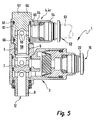
- FIGS 3 to 5 show the connection device 1 in the different equipment variants, with the base unit 3 in Figure 3 with the first venting unit 4a, in Figure 4 with the second ventilation unit 4b and in Figure 5 is equipped with the third ventilation unit 4c.
- the base unit 3 has an elongated fastening part 7 with opposite first and second end regions 8, 9. At the first end area 8 there is a working connection 12 provided, a vent connection at the second end region 9 13th
- a pivot part 14 is rotatable on the fastening part 7 attached. There is a sideways projecting feed connection on it 15 provided.
- the first interface 5 is located at the vent connection 13 and enables the aforementioned optional connection the ventilation units 4, with a mechanical and a fluidic connection between the base unit 3 and the relevant ventilation unit 4 is produced.
- the working connection 2 serves to connect the connection device 1 with the fluid technology component already mentioned 2.
- the working connection 12 via a connecting thread 16, with which it turns into a complementary Fastening thread 17 of the fluidic component 2 producing both mechanical and fluidic Connection is screwable ( Figure 3).
- the feed connector 15 is for connecting one in FIG. 3 Provided by dash-dotted lines fluid line 18 which is required for the operation of the fluid power component 2 Pressure medium - here: compressed air - from a pressure source is fed.
- Connecting the fluid line 18 can be done by a simple plug connection, to which Purpose of the supply connection 15 with suitable plug connection means 22 is equipped. The inserted fluid line 18 is held under seal. If necessary can the fluid line 18 by appropriate actuation of the Plug connection means 22 can be pulled out again at any time.
- the supply connection 15 for connecting the Fluid line 18 also have screw connection means 23, such as they are indicated by dash-dotted lines in FIG. 1. It deals here in particular an internal thread into which a provided with an external thread fluid line under sealing can be screwed in.
- the swivel part 14 is provided with a quick exhaust valve 24 equipped that in the connection between the three connections 12, 13, 15 is switched on. It's like one so-called shuttle valve built.
- a valve member is a movable sealing sleeve 25 is provided, which in the pivoting part 14 is integrated.
- the swivel part 14 contains a swivel part base body 26, which has an annular body 27 which is coaxial with the fastening part 7 is attached. A protrudes from the ring body 27 Pipe section 28 of the swivel part base body 26 transversely to the longitudinal axis 32 of the fastening part 7 away, in the from the free end forth a feed connection body having the feed connection 15 33 is inserted.
- the feed connector body is preferred 33 screwed into the pipe section 28 with sealing.
- the sealing sleeve 25 is between the swivel base body 26 and the feed connector body 33, wherein but in the longitudinal direction of the feed connector body 33 between two end positions is movable.
- the sealing sleeve 25 sits in a receiving space 34, the dividing them into a first chamber 35 and a second chamber 36.
- the supply connection opens into the first chamber 15 communicating first fluid channel 37.
- In the fastening part 7 assigned second chamber 36 opens out with the Second fluid channel 38 communicating work port 12 and a communicating with the vent port 13 third fluid channel 39.
- the latter two fluid channels 38, 39 each end at the other end on the assigned first and second end regions 8, 9 and each contain one between the outer periphery of the fastening part 7 and the ring channel 42 defined the inner circumference of the ring body 27 or 43, of which a branch channel leading into the first chamber 35 44 or 45 of the pivot part 14 goes off.
- the sealing sleeve 25 contains a central body 46 on which a circumferential sealing lip 47 is formed.
- connection device 1 allows through the optional combination the base unit 3 with one of the provided Ventilation units 4 the respective circumstances to take optimal account.
- the corresponding ventilation unit 4 with its second interface 6 at the second end region 9 of the fastening part 7 provided first interface 5 attached.
- FIG 3 shows the connection device 1 in the with the mentioned first venting unit 4, 4a equipped Status.
- This first ventilation unit 4, 4a is equipped with a Exhaust throttle 48 and equipped with a silencer 51.
- the preferably variably adjustable exhaust air throttle 48 enables the outflow speed to be influenced the compressed air, which in connection with fluid-operated drives especially used to speed to influence the drive part, for example a piston.
- Silencer 51 is the sound of the exiting Air and thus the operating noise of the connection device 1 steamed.
- FIG. 4 shows the connection device 1 in the second Venting unit 4, 4b equipped state. This contains no exhaust throttle 48 and allows an unrestricted Outflow of compressed air. However, here too a silencer 51 is provided for noise reduction.
- the venting unit 4c has no throttling means.
- a fluid line connection 52 is provided, to which a Connect further fluid line 53 indicated by dash-dotted lines leaves, so that the exhaust air can be exhausted and not in the immediate vicinity of the connection device 1 flows out.
- the fluid line port 52 is expediently provided with plug connection means 54 which sealing a detachable plug connection of the others Allow fluid line 53.
- the first and second interfaces 5, 6 are preferred Screw interfaces designed. They allow attachment the respective ventilation unit 4 in the context of a Screwing.
- the first interface 5 in an extension of the third fluid channel 39 an internal thread included, in which the ventilation unit 4 with an external thread having fastening attachment 55 screwed is.
- the attachment extension 55 is part of a banjo bolt 56 of the relevant ventilation unit 4. This has on the the end opposite the attachment extension 55 a e.g. Actuating part 57 formed by a polygon on which the banjo bolt 56 can be handled when it is in the fastening part 7 screwed in or unscrewed from this becomes.
- a ventilation channel 58 is located in the hollow screw 56. One ends at the area of the second interface 6 off, so that with the ventilation unit 4 installed the third fluid channel 39 of the base unit 3 in fluidic Connection is established.
- the ventilation channel 58 opens to the outer circumference of the Hollow screw 56, which was distributed over several circumferences Branch channels 59 can happen.
- the silencer 51 a sleeve-like shape. It is coaxial with the Banjo bolt 56 plugged in and at the level of the mouths of the Branch channels 59 placed. Coaxial between the silencer 51 and the outer circumference of the hollow screw 56 is a Annulus 63 in which the outflowing air is distributed may before it passes through the muffler 51.
- the muffler 51 consists of muffler material known per se, for example a sintered material, and has one porous structure that allows air to flow through allows simultaneous noise reduction.
- the banjo bolts are identical educated. Overall, the arrangement differs 5 used third venting unit 4, 4c of the second used in the arrangement according to FIG. 4 Ventilation unit 4b only in that instead of the silencer 51 a further pivot part 64 on the banjo bolt 56 is arranged rotatably, the fluid line connection 52nd and which includes an internal fluid channel 65 which connects the fluid line connection 52 to the annular space 63.
- seals 66 are provided axially on both sides of the annular space 63.
- Comparable seals 67 are located axially on both sides of the two annular spaces provided on the base unit 3 between the fastening part 7 and the swivel part 14.
- the first ventilation unit 4a according to FIG. 3 differs differs from the second ventilation unit 4b according to FIG. 4 due to the additional presence of an exhaust throttle 48.
- the exhaust throttle 48 expediently contains the actuating section 57 coaxial throttle element 68, the immersed in the ventilation duct 58.
- the throttle member 68 is adjustable and positionable relative to banjo bolt 56, different immersion depths and therefore different Obtain throttling intensities. To set this is Throttle member 68 at the outer end with an operating section 69 provided.
- connection device can be retrofitted at any time 1 to another type of ventilation unit 4 possible.
- the above-mentioned feed connector body 33 is on one Interface 73 of the swivel base body 26 is mounted.
- This interface 73 expediently enables the optional Attachment of supply connection bodies different Type. So, from case to case, optional supply connection bodies to be assembled, which is in the design distinguish the supply connection 15. This enables, for example the installation of supply connections 15 with different Connection sizes or with different types Connection means, for example in the form of Plug connection means 22 or screw connection means 23. In this way, there is also a high degree of variability Regarding the connection options for the compressed air supplying fluid line 18.
Abstract
Description
Die vorliegende Erfindung betrifft eine Anschlussvorrichtung für Fluidleitungen, mit deren Hilfe es möglich ist, eine Fluidieitung an eine fluidtechnische Komponente, beispielsweise einen fluidbetätigten Antrieb anzuschließen.The present invention relates to a connection device for fluid lines, with the help of which it is possible to provide a fluid line to a fluid power component, for example to connect a fluid operated drive.
Eine aus der DE 200 08 129 U bekannte Anschlussvorrichtung für Fluidleitungen enthält ein längliches, nach Art einer Hohlschraube ausgebildetes Befestigungsteil, das an einem ersten Endbereich einen Arbeitsanschluss aufweist, der in die zugeordnete fluidtechnische Komponente eingeschraubt werden kann. Ein auf das Befestigungsteil drehbar aufgestecktes Schwenkteil enthält einen Speiseanschluss, an dem eine Fluidleitung festlegbar ist, die Druckluft heranführt. Der Speiseanschluss repräsentiert gleichzeitig einen Entlüftungsanschluss, da über ihn auch die aus der fluidtechnischen Komponente zurückströmende Druckluft abgeführt wird. Das Befestigungsteil ist mit einem Rückschlagventil und einer Abluftdrossel ausgestattet, wobei das Rückschlagventil dafür sorgt, dass die von der fluidtechnischen Komponente zurückströmende Druckluft nur über die Abluftdrossel hinweg ausströmen kann.A connection device known from DE 200 08 129 U for fluid lines contains an elongated, sort of Banjo bolt formed fastener that on a has a working connection in the first end region assigned fluid technology components are screwed in can. One rotatably attached to the fastening part Swivel part contains a feed connection to which a fluid line can be determined, the compressed air introduces. The feed connection represents a vent connection at the same time, because of him also from the fluid technology component back flowing compressed air is discharged. The fastener is with a check valve and an exhaust air throttle equipped, the check valve ensures that the flowing back from the fluid power component Compressed air can only flow out through the exhaust air throttle.
Die bekannte Anschlussvorrichtung hat einen an den geschilderten Verwendungszweck speziell angepassten Aufbau. Dies führt dazu, dass für andere Anwendungsfälle komplett andere Bauarten von Anschlussvorrichtungen benötigt werden. So verwendet man in Fällen, bei denen keine Abluftdrosselung erforderlich ist, Anschlussvorrichtungen der beispielsweise in der DE 94 15 871 U1 beschriebenen Bauart, die ein von einer Hohlschraube gebildetes Befestigungsteil aufweisen, das keine Abluftdrossel enthält und somit einen freien Fluiddurchgang gewährleistet. Wie im Falle der DE 200 08 129 U verfügt die Anschlussvorrichtung gemäß DE 94 15 871 U1 auch nur über zwei Anschlüsse für die Zufuhr und Abfuhr des Druckmediums. Dadurch sind zusätzlich aufwendige Steuerventile erforderlich, wenn das Druckmedium in zwei Richtungen durch die Anschlussvorrichtung hindurchgeleitet werden soll.The known connection device has one of the described Purpose specially adapted structure. This leads to completely different for other use cases Types of connection devices are required. So used one in cases where exhaust air throttling is not required is, connecting devices, for example in the DE 94 15 871 U1 described type, which is a banjo bolt have formed fastening part that has no exhaust throttle contains and thus ensures a free passage of fluid. As in the case of DE 200 08 129 U, the connection device has according to DE 94 15 871 U1, only over two Connections for the supply and discharge of the print medium. Thereby complex control valves are required, if the print medium in two directions through the connector to be passed through.
Es ist daher die Aufgabe der vorliegenden Erfindung, eine Anschlussvorrichtung für Fluidleitungen zu schaffen, deren Aufbau eine Verwendung für unterschiedliche Anwendungsfälle ermöglicht.It is therefore the object of the present invention to provide a connection device to create for fluid lines, their construction allows use for different applications.
Gelöst wird diese Aufgabe mit einer Anschlussvorrichtung für Fluidleitungen, mit einer Basiseinheit, die ein längliches Befestigungsteil mit einander entgegengesetzten ersten und zweiten Endbereichen aufweist, auf das ein Schwenkteil drehbar aufgesteckt ist, das einen Speiseanschluss aufweist, der zum Anschließen einer ein Druckmedium einspeisenden Fluidleitung vorgesehen ist, mit einem am ersten Endbereich des Befestigungsteiles vorgesehenen Arbeitsanschluss zum Verbinden mit einer fluidtechnischen Komponente und einem am zweiten Endbereich des Befestigungsteiles vorgesehenen Entlüftungsanschluss, wobei das Schwenkteil mit einem in die Verbindung zwischen den drei Anschlüssen eingeschalteten Schnellentlüftungsventil ausgestattet ist, und mit einer dem Entlüftungsanschluss zugeordneten ersten Schnittstelle am Befestigungsteil, die vorgesehen ist, um wahlweise unterschiedliche Typen von Entlüftungseinheiten zu befestigen, unter denen sich wenigstens eine Entlüftungseinheit mit Abluftdrossel und wenigstens eine Entlüftungseinheit ohne Abluftdrossel befindet und die jeweils mit einer zu der ersten Schnittstelle komplementären zweiten Schnittstelle versehen sind. This task is solved with a connection device for Fluid lines, with a base unit, which is an elongated Fastener with opposite first and has second end regions on which a pivoting part is rotatable is plugged in, which has a feed connection, the for connecting a fluid line feeding a pressure medium is provided with one at the first end region of the fastening part provided working connection for connection with a fluidic component and one on the second End area of the fastening part provided ventilation connection, wherein the swivel part with one in the connection Quick exhaust valve switched on between the three connections is equipped, and with a vent connection assigned first interface on the fastening part, which is provided to selectively different types to attach ventilation units, among which at least a ventilation unit with exhaust throttle and at least there is a ventilation unit without exhaust air throttle and each with one complementary to the first interface second interface are provided.
Die am Entlüftungsanschluss des Befestigungsteiles vorgesehene Schnittstelle ermöglicht es, dem jeweiligen Anwendungszweck entsprechend unterschiedliche Arten von Entlüftungseinheiten zu installieren. Auf diese Weise lassen sich unterschiedliche Bauformen der Anschlussvorrichtung unter Verwendung einer großen Anzahl von Gleichteilen realisieren. In Verbindung mit dem am Schwenkteil vorgesehenen Schnellentlüftungsventil kann zudem die vom Arbeitsanschluss zurückströmende Druckluft über die von Fall zu Fall vorgesehene spezielle Entlüftungseinheit gesondert und ohne Verwendung des Speiseanschlusses abgeführt werden. Die ermöglicht die Realisierung von Entlüftungsquerschnitten, die nicht an den Querschnitt der am Speiseanschluss angeschlossenen Fluidleitung gebunden sind, so dass eine sehr schnelle Entlüftung stattfinden kann.The one provided on the vent connection of the fastening part Interface enables the respective application purpose accordingly different types of ventilation units to install. In this way, different Types of connection device using realize a large number of identical parts. In Connection with the quick exhaust valve provided on the swivel part can also flow back from the work connection Compressed air over the special provided from case to case Venting unit separately and without using the Supply connection are discharged. This enables implementation of ventilation cross sections that are not related to the cross section the fluid line connected to the feed connection are bound so that a very quick ventilation takes place can.
Vorteilhafte Weiterbildungen der Erfindung gehen aus den Unteransprüchen hervor.Advantageous developments of the invention emerge from the subclaims out.
Bei der dem Entlüftungsanschluss zugeordneten ersten Schnittstelle handelt es sich zweckmäßigerweise um eine Schraub-Schnittstelle, an der sich die für den Einsatzzweck gewünschte Entlüftungseinheit sehr einfach im Rahmen eines Schraubvorganges fixieren lässt.At the first interface assigned to the vent connection it is expedient to use a screw interface, at which the desired for the intended purpose Venting unit very simple in the context of a screwing process can be fixed.
Wenn die erste Schnittstelle zur lösbaren Befestigung der Entlüftungseinheiten ausgebildet ist, kann ein- und dieselbe Basiseinheit sehr einfach nachträglich für unterschiedliche Anwendungszwecke umgerüstet werden.If the first interface for detachable attachment of the Venting units is formed, can one and the same Base unit very easy to retrofit for different ones Application purposes.
Mindestens eine der Entlüftungseinheiten enthält zweckmäßigerweise einen Schalldämpfer zur Dämpfung des Schalls der austretenden Luft. Ein solcher Schalldämpfer kann sowohl bei einer mit einer Abluftdrossel ausgestatteten Entlüftungseinheit als auch bei einer keine Abluftdrossel enthaltenden Entlüftungseinheit vorteilhaft verwendet werden.At least one of the ventilation units expediently contains a silencer to dampen the sound of the escaping air. Such a silencer can both a ventilation unit equipped with an exhaust air throttle as well as a ventilation unit that does not contain an exhaust air throttle can be used advantageously.
Um am Einsatzort der Anschlussvorrichtung ein durch ausströmende Druckluft erzeugtes Geräusch zu verhindern, kann die Anschlussvorrichtung an der am Befestigungsteil vorgesehenen ersten Schnittstelle mit einer Entlüftungseinheit bestückt werden, die einen Fluidleitungsanschluss aufweist, an dem sich eine zur gefassten Luftabfuhr dienende Fluidleitung anschließen lässt. Der Fluidleitungsanschluss ist zweckmäßigerweise mit Steckanschlussmitteln ausgestattet, die eine lösbare Steckverbindung der Fluidleitung ermöglichen.To flow through at the place of use of the connection device Compressed air can prevent noise Connection device on the provided on the fastening part first interface equipped with a ventilation unit which has a fluid line connection on which a fluid line is used to collect air leaves. The fluid line connection is expedient equipped with plug-in connection means that a detachable Allow plug connection of the fluid line.
Um eine bedarfsgemäße Positionierung der von der Entlüftungseinheit abgehenden Fluidleitung zu ermöglichen, ist die zur gefassten Luftabfuhr dienende Entlüftungseinheit zweckmäßigerweise mit einer zur Verbindung mit dem Befestigungsteil vorgesehenen Hohlschraube und einem drehbar auf die Hohlschraube aufgesteckten Schwenkteil ausgestattet, wobei das Schwenkteil den Fluidanschluss aufweist.To position the ventilation unit as required To allow outgoing fluid line is the venting unit used for air removal expediently with one for connection to the fastening part provided banjo bolt and one rotatable on the banjo bolt fitted swivel part, the Swivel part has the fluid connection.
Von Fall zu Fall kann der Speiseanschluss für den Anschluss der zugeordneten Fluidleitung mit Steckanschlussmitteln oder mit Schraubanschlussmitteln ausgestattet sein.From case to case, the power connector can be used for connection the associated fluid line with plug connection means or be equipped with screw connection means.
Auf jeden Fall ist es vorteilhaft, wenn das Schwenkteil zur drehbaren Lagerung am Befestigungsteil über einen Schwenkteil-Grundkörper verfügt, an dem ein den Speiseanschluss aufweisender Speiseanschlusskörper befestigt ist. In diesem Zusammenhang besteht die Möglichkeit, unterschiedliche Typen von Speiseanschlusskörpern bereitzustellen, die in Abhängigkeit vom Anwendungsfall wahlweise am Schwenkteil-Grundkörper festlegbar sind. Es lassen sich dadurch nicht nur verschiedene Bauarten der Anschlussmittel, sondern auch verschiedene Anschlussgrößen variabel vorsehen. In any case, it is advantageous if the swivel part for rotatable mounting on the mounting part via a swivel base on which a has the feed connection Feed connector body is attached. In this context there is a possibility of different types of supply connector bodies that are dependent depending on the application, optionally on the swivel base can be determined. It can not only be different Types of connection means, but also different Provide variable connection sizes.
Nachfolgend wird die Erfindung anhand der beiliegenden Zeichnung näher erläutert. In dieser zeigen:
Figur 1- eine bevorzugte Bauform der erfindungsgemäßen Anschlussvorrichtung im Längsschnitt, wobei mehrere alternativ an der Basiseinheit der Anschlussvorrichtung festlegbare Entlüftungseinheiten schematisch strichpunktiert angedeutet sind,
Figur 2- eine Draufsicht auf die Basiseinheit der Anschlussvorrichtung
aus
Figur 1, Figur 3- eine Längsschnittdarstellung der Anschlussvorrichtung
aus
Figur 1, ausgestattet mit einer einen Schalldämpfer und eine Abluftdrossel enthaltenden Entlüftungseinheit, wobei strichpunktiert ein Ausschnitt einer fluidtechnischen Komponente illustriert ist, an der die Anschlussvorrichtung festlegbar ist, - Figur 4
- in Längsschnittdarstellung die Anschlussvorrichtung
aus
Figur 1, ausgestattet mit einer Entlüftungseinheit ohne Abluftdrossel, jedoch mit Schalldämpfer, und Figur 5- eine Längsschnittdarstellung der Anschlussvorrichtung
aus
Figur 1, ausgestattet mit einer Entlüftungseinheit ohne Abluftdrossel und mit einem Fluidleitungsanschluss zur gefassten Luftabfuhr.
- Figure 1
- a preferred design of the connection device according to the invention in longitudinal section, wherein several ventilation units that can alternatively be fixed on the base unit of the connection device are indicated schematically in dash-dot lines,
- Figure 2
- 2 shows a plan view of the base unit of the connection device from FIG. 1,
- Figure 3
- 2 shows a longitudinal sectional view of the connection device from FIG. 1, equipped with a ventilation unit containing a muffler and an exhaust air throttle, with a dash-dot line illustrating a section of a fluid technology component on which the connection device can be fixed,
- Figure 4
- in longitudinal section the connection device from Figure 1, equipped with a ventilation unit without exhaust throttle, but with silencer, and
- Figure 5
- 2 shows a longitudinal sectional view of the connection device from FIG. 1, equipped with a ventilation unit without an exhaust air throttle and with a fluid line connection for air removal.
Die in ihrer Gesamtheit mit Bezugsziffer 1 bezeichnete Anschlussvorrichtung
ist beim Ausführungsbeispiel vorgesehen,
um bei der Zufuhr und Abfuhr von Druckluft in einen bzw. aus
einem fluidbetätigten Antrieb mitzuwirken, der in Figur 3
partiell angedeutet und mit Bezugsziffer 2 versehen ist. Anstelle
des fluidbetätigten Antriebes 2 kann aber auch jede
beliebige andere fluidtechnische Komponente mit der Anschlussvorrichtung
ausgestattet werden, beispielsweise ein
Ventil oder ein Druckbehälter.The connection device designated in its entirety with
Die Anschlussvorrichtung 1 setzt sich im wesentlichen aus einer
Basiseinheit 3 und einer Entlüftungseinheit 4 zusammen,
wobei die Basiseinheit 3 eine erste Schnittstelle 5 aufweist,
an der die Entlüftungseinheit 4 mit einer komplementären
zweiten Schnittstelle 6 festlegbar ist.The connecting
Durch die Realisierung der an der Basiseinheit 3 vorgesehenen
ersten Schnittstelle 5 besteht die vorteilhafte Möglichkeit,
wahlweise unterschiedliche Typen von Entlüftungseinheiten 4
an der Basiseinheit 3 zu montieren, in Abhängigkeit von den
Gegebenheiten des jeweiligen Anwendungsfalles. In Figur 1
sind drei mögliche Entlüftungseinheiten angedeutet, die über
voneinander abweichende fluidtechnische Ausstattungen verfügen
und die zur besseren Unterscheidung ergänzend mit den Bezugsziffern
4a, 4b und 4c versehen sind.By implementing the provided on the
Die Figuren 3 bis 5 zeigen die Anschlussvorrichtung 1 in den
unterschiedlichen Ausstattungsvarianten, wobei die Basiseinheit
3 in Figur 3 mit der ersten Entlüftungseinheit 4a, in
Figur 4 mit der zweiten Entlüftungseinheit 4b und in Figur 5
mit der dritten Entlüftungseinheit 4c ausgestattet ist.Figures 3 to 5 show the
Die Basiseinheit 3 verfügt über ein längliches Befestigungsteil
7 mit einander entgegengesetzten ersten und zweiten Endbereichen
8, 9. Am ersten Endbereich 8 ist ein Arbeitsanschluss
12 vorgesehen, am zweiten Endbereich 9 ein Entlüftungsanschluss
13. The
Auf das Befestigungsteil 7 ist ein Schwenkteil 14 drehbar
aufgesteckt. An ihm ist ein seitwärts ragender Speiseanschluss
15 vorgesehen.A
Die erste Schnittstelle 5 befindet sich an dem Entlüftungsanschluss
13 und ermöglicht das erwähnte wahlweise Anschließen
der Entlüftungseinheiten 4, wobei gleichzeitig eine mechanische
und eine fluidische Verbindung zwischen der Basiseinheit
3 und der betreffenden Entlüftungseinheit 4 hergestellt wird.The
Der Arbeitsanschluss 2 dient zum Verbinden der Anschlussvorrichtung
1 mit der schon erwähnten fluidtechnischen Komponente
2. Beim Ausführungsbeispiel verfügt der Arbeitsanschluss
12 über ein Anschlussgewinde 16, mit dem er in ein komplementäres
Befestigungsgewinde 17 des fluidtechnischen Bauteiles 2
unter Herstellung einer sowohl mechanischen als auch fluidischen
Verbindung einschraubbar ist (Figur 3).The working
Der Speiseanschluss 15 ist zum Anschließen einer in Figur 3
strichpunktiert angedeuteten Fluidleitung 18 vorgesehen, über
die das für den Betrieb der fluidtechnischen Komponente 2 erforderliche
Druckmedium - hier: Druckluft - von einer Druckquelle
zugeführt wird. Das Anschließen der Fluidleitung 18
kann durch eine einfache Steckverbindung geschehen, zu welchem
Zweck der Speiseanschluss 15 mit geeigneten Steckanschlussmitteln
22 ausgestattet ist. Die eingesteckte Fluidleitung
18 wird unter Abdichtung festgehalten. Bei Bedarf
kann die Fluidleitung 18 durch entsprechende Betätigung der
Steckanschlussmittel 22 jederzeit wieder herausgezogen werden.The
Alternativ kann der Speiseanschluss 15 für den Anschluss der
Fluidleitung 18 auch Schraubanschlussmittel 23 aufweisen, wie
sie in Figur 1 strichpunktiert angedeutet sind. Es handelt
sich hier insbesondere um ein Innengewinde, in das sich eine
mit einem Außengewinde versehen Fluidleitung unter Abdichtung
einschrauben lässt.Alternatively, the
Das Schwenkteil 14 ist mit einem Schnellentlüftungsventil 24
ausgestattet, das in die Verbindung zwischen den drei Anschlüssen
12, 13, 15 eingeschaltet ist. Es ist ähnlich einem
sogenannten Wechselventil aufgebaut. Als Ventilglied ist eine
bewegliche Dichtmanschette 25 vorgesehen, die in das Schwenkteil
14 integriert ist.The
Das Schwenkteil 14 enthält einen Schwenkteil-Grundkörper 26,
der einen Ringkörper 27 aufweist, der koaxial auf das Befestigungsteil
7 aufgesteckt ist. Von dem Ringkörper 27 ragt ein
Rohrstück 28 des Schwenkteil-Grundkörpers 26 quer zur Längsachse
32 des Befestigungsteiles 7 weg, in das vom freien Ende
her ein den Speiseanschluss 15 aufweisender Speiseanschlusskörper
33 eingesetzt ist. Bevorzugt ist der Speiseanschlusskörper
33 in das Rohrstück 28 unter Abdichtung eingeschraubt.The
Die Dichtmanschette 25 ist zwischen dem Schwenkteil-Grundkörper
26 und dem Speiseanschlusskörper 33 gefangen, wobei
sie aber in Längsrichtung des Speiseanschlusskörpers 33 zwischen
zwei Endstellungen bewegbar ist.The sealing
Die Dichtmanschette 25 sitzt in einem Aufnahmeraum 34, den
sie in eine erste Kammer 35 und eine zweite Kammer 36 unterteilt.
In die erste Kammer mündet ein mit dem Speiseanschluss
15 kommunizierender erster Fluidkanal 37. In die dem Befestigungsteil
7 zugeordnete zweite Kammer 36 mündet ein mit dem
Arbeitsanschluss 12 kommunizierender zweiter Fluidkanal 38
sowie ein mit dem Entlüftungsanschluss 13 kommunizierender
dritter Fluidkanal 39. Die beiden letztgenannten Fluidkanäle
38, 39 münden jeweils andernends stirnseitig am zugeordneten
ersten bzw. zweiten Endbereich 8, 9 aus und enthalten jeweils
einen zwischen dem Außenumfang des Befestigungsteils 7 und
dem Innenumfang des Ringkörpers 27 definierten Ringkanal 42
bzw. 43, von dem ein in die erste Kammer 35 führender Zweigkanal
44 bzw. 45 des Schwenkteils 14 abgeht.The sealing
Die Dichtmanschette 25 enthält einen Zentralkörper 46, an dem
eine umlaufende Dichtlippe 47 angeformt ist.The sealing
Wird über den Speiseanschluss 15 Druckluft eingespeist, verschiebt
diese die Dichtmanschette 25, so dass der Zentralkörper
46 die Ausmündung des dritten Fluidkanals 39 verschließt.
Gleichzeitig wird die Dichtlippe 47 nach innen verformt, so
dass die Druckluft an der Dichtmanschette 25 vorbei in den
zweiten Fluidkanal 38 und somit zum Arbeitsanschluss 12 strömen
kann. Von dort tritt sie in die angeschlossene fluidtechnische
Komponente 2 ein.If compressed air is fed in via the
Um in der fluidtechnischen Komponente 2 befindliche Druckluft
abströmen zu lassen, wird die Druckluftzufuhr über die Fluidleitung
18 zum Speiseanschluss 15 unterbrochen und am Speiseanschluss
15 zweckmäßigerweise atmosphärischer Druck angelegt.
Hierzu kann ein nicht näher dargestelltes Ventil verwendet
werden. Auf diese Weise ist die am Arbeitsanschluss 12
anstehende Druckluft in der Lage, die Dichtmanschette 25 bis
zur Anlage am Speiseanschlusskörper 33 zurückzuschieben, wobei
gleichzeitig die Dichtlippen 47 nach außen in dichtenden
Kontakt mit dem Schwenkteil-Grundkörper 26 gedrückt werden.
Die Druckluft kann nun vom Arbeitsanschluss 12 durch die erste
Kammer 35 hindurch zum Entlüftungsanschluss 13 ausströmen.To compressed air located in the
Die Art und Weise, wie die Druckluft ausströmen soll variiert
in Abhängigkeit von der Art der fluidtechnischen Komponente
und den Einsatzbedingungen der Gesamtanordnung. Die Anschlussvorrichtung
1 gestattet es, durch die wahlweise Kombination
der Basiseinheit 3 mit einer der zur Verfügung gestellten
Entlüftungseinheiten 4 den jeweiligen Gegebenheiten
optimal Rechnung zu tragen. Je nachdem, welche Entlüftungsart
gewünscht ist, wird die entsprechende Entlüftungseinheit 4
mit ihrer zweiten Schnittstelle 6 an der am zweiten Endbereich
9 des Befestigungsteiles 7 vorgesehenen ersten Schnittstelle
5 befestigt.The way in which the compressed air should flow out varies
depending on the type of fluid power component
and the conditions of use of the overall arrangement. The
Die Figur 3 zeigt die Anschlussvorrichtung 1 im mit der eingangs
erwähnten ersten Entlüftungseinheit 4, 4a ausgestatteten
Zustand. Diese erste Entlüftungseinheit 4, 4a ist mit einer
Abluftdrossel 48 und mit einem Schalldämpfer 51 ausgestattet.
Die vorzugsweise variabel einstellbare Abluftdrossel
48 ermöglicht eine Beeinflussung der Abströmgeschwindigkeit
der Druckluft, was im Zusammenhang mit fluidbetätigten Antrieben
insbesondere dazu verwendet wird, die Geschwindigkeit
des Antriebsteiles, beispielsweise ein Kolben, zu beeinflussen.
Durch den der Abluftdrossel 48 in Ausströmrichtung nachgeordneten
Schalldämpfer 51 wird der Schall der austretenden
Luft und somit das Betriebsgeräusch der Anschlussvorrichtung
1 gedämpft.Figure 3 shows the
Die Figur 4 zeigt die Anschlussvorrichtung 1 im mit der zweiten
Entlüftungseinheit 4, 4b ausgestatteten Zustand. Diese
enthält keine Abluftdrossel 48 und ermöglicht ein uneingeschränktes
Abströmen der Druckluft. Allerdings ist auch hier
ein Schalldämpfer 51 zur Geräuschreduzierung vorgesehen.FIG. 4 shows the
Im Falle der Figur 5 schließlich ist die Anschlussvorrichtung
1 im mit der dritten Entlüftungseinheit 4, 4c ausgestatteten
Zustand abgebildet. Wie bei der Bauform gemäß Figur 4 enthält
die Entlüftungseinheit 4c keine Drosselmittel. Darüber hinaus
ist aber auch kein Schalldämpfer vorhanden. Statt dessen ist
ein Fluidleitungsanschluss 52 vorgesehen, an den sich eine
strichpunktiert angedeutete weitere Fluidleitung 53 anschließen
lässt, so dass die Abluft gefasst abgeführt werden kann
und nicht im unmittelbaren Umgebungsbereich der Anschlussvorrichtung
1 ausströmt. Der Fluidleitungsanschluss 52 ist
zweckmäßigerweise mit Steckanschlussmitteln 54 versehen, die
unter Abdichtung eine lösbare Steckverbindung der weiteren
Fluidleitung 53 ermöglichen.Finally, in the case of FIG. 5, the
Bevorzugt sind die erste und zweite Schnittstelle 5, 6 als
Schraub-Schnittstellen ausgebildet. Sie ermöglichen eine Befestigung
der jeweiligen Entlüftungseinheit 4 im Rahmen eines
Schraubvorganges. Hierzu kann die erste Schnittstelle 5 in
einer Erweiterung des dritten Fluidkanals 39 ein Innengewinde
enthalten, in das die Entlüftungseinheit 4 mit einem ein Außengewinde
aufweisenden Befestigungsfortsatz 55 einschraubbar
ist.The first and
Der Befestigungsfortsatz 55 ist Bestandteil einer Hohlschraube
56 der betreffenden Entlüftungseinheit 4. Diese hat an dem
dem Befestigungsfortsatz 55 entgegengesetzten Ende eine z.B.
von einem Mehrkant gebildete Betätigungspartie 57, an der
sich die Hohlschraube 56 handhaben lässt, wenn sie in das Befestigungsteil
7 eingeschraubt oder aus diesem herausgeschraubt
wird.The
In der Hohlschraube 56 befindet sich ein Entlüftungskanal 58.
Dieser mündet einenends im Bereich der zweiten Schnittstelle
6 aus, so dass er bei installierter Entlüftungseinheit 4 mit
dem dritten Fluidkanal 39 der Basiseinheit 3 in fluidischer
Verbindung steht.A
Andernends mündet der Entlüftungskanal 58 zum Außenumfang der
Hohlschraube 56 aus, was über mehrere umfangsmäßig verteilte
Zweigkanäle 59 geschehen kann.At the other end, the
Bei den Ausgestaltungen der Figuren 3 und 4 hat der Schalldämpfer
51 eine hülsenartige Gestalt. Er ist koaxial auf die
Hohlschraube 56 aufgesteckt und auf Höhe der Ausmündungen der
Zweigkanäle 59 platziert. Koaxial zwischen dem Schalldämpfer
51 und dem Außenumfang der Hohlschraube 56 befindet sich ein
Ringraum 63, in dem sich die ausströmende Luft verteilen
kann, bevor sie durch den Schalldämpfer 51 hindurchtritt.In the embodiments of Figures 3 and 4, the silencer
51 a sleeve-like shape. It is coaxial with the
Der Schalldämpfer 51 besteht aus an sich bekanntem Schalldämpfmaterial,
beispielsweise ein Sintermaterial, und hat einen
porösen Aufbau, der der Luft ein Hindurchströmen mit
gleichzeitiger Geräuschminderung ermöglicht.The
Im Falle der Figuren 4 und 5 sind die Hohlschrauben identisch
ausgebildet. Insgesamt unterscheidet sich die bei der Anordnung
gemäß Figur 5 verwendete dritte Entlüftungseinheit 4, 4c
von der bei der Anordnung gemäß Figur 4 eingesetzten zweiten
Entlüftungseinheit 4b nur dadurch, dass anstelle des Schalldämpfers
51 ein weiteres Schwenkteil 64 auf der Hohlschraube
56 drehbar angeordnet ist, das den Fluidleitungsanschluss 52
aufweist und das einen internen Fluidkanal 65 enthält, der
den Fluidleitungsanschluss 52 mit dem Ringraum 63 verbindet.In the case of Figures 4 and 5, the banjo bolts are identical
educated. Overall, the arrangement differs
5 used third venting unit 4, 4c
of the second used in the arrangement according to FIG. 4
Ventilation unit 4b only in that instead of the silencer
51 a
Zwischen dem weiteren Schwenkteil 64 und der Hohlschraube 56
sind, axial beidseits des Ringraumes 63, Dichtungen 66 vorgesehen.
Vergleichbare Dichtungen 67 befinden sich axial beidseits
der beiden an der Basiseinheit 3 vorgesehenen Ringräume
zwischen dem Befestigungsteil 7 und dem Schwenkteil 14.Between the
Durch die beiden Schwenkteile 14, 64 ist es möglich, den
Speiseanschluss 22 und den Fluidleitungsanschluss 52 durch
Verdrehen unabhängig voneinander drehwinkelmäßig bezüglich
der Längsachse 32 zu positionieren.By the two
Die erste Entlüftungseinheit 4a gemäß Figur 3 unterscheidet
sich von der zweiten Entlüftungseinheit 4b gemäß Figur 4
durch das zusätzliche Vorhandensein einer Abluftdrossel 48.
Die Abluftdrossel 48 enthält zweckmäßigerweise ein die Betätigungspartie
57 koaxial durchsetzendes Drosselglied 68, das
in den Entlüftungskanal 58 eintaucht. Das Drosselglied 68 ist
relativ zur Hohlschraube 56 verstellbar und positionierbar,
um unterschiedliche Eintauchtiefen und somit unterschiedliche
Drosselungsintensitäten zu erhalten. Zum Einstellen ist das
Drosselglied 68 am äußeren Ende mit einem Betätigungsabschnitt
69 versehen.The first ventilation unit 4a according to FIG. 3 differs
differs from the second ventilation unit 4b according to FIG. 4
due to the additional presence of an
Zweckmäßigerweise ermöglichen die beiden Schnittstellen 5, 6
eine lösbare Befestigung der jeweiligen Entlüftungseinheit 4.
Auf diese Weise ist zu jeder Zeit eine Umrüstung der Anschlussvorrichtung
1 auf einen anderen Typ von Entlüftungseinheit
4 möglich.The two
Der oben erwähnte Speiseanschlusskörper 33 ist an einer
Schnittstelle 73 des Schwenkteil-Grundkörpers 26 montiert.
Diese Schnittstelle 73 ermöglicht zweckmäßigerweise die wahlweise
Befestigung von Speiseanschlusskörpern unterschiedlichen
Typs. So können von Fall zu Fall wahlweise Speiseanschlusskörper
montiert werden, die sich in der Ausgestaltung
des Speiseanschlusses 15 unterscheiden. Dies ermöglicht beispielsweise
die Installation von Speiseanschlüssen 15 mit unterschiedlichen
Anschlussgrößen oder mit unterschiedlich gearteten
Anschlussmitteln, beispielsweise in Gestalt von
Steckanschlussmitteln 22 oder von Schraubanschlussmitteln 23.
Auf diese Weise ergibt sich eine hohe Variabilität auch in
Bezug auf die Anschlussmöglichkeiten für die die Druckluft
zuführende Fluidleitung 18.The above-mentioned
Claims (15)
mit einem am ersten Endbereich (8) des Befestigungsteiles (7) vorgesehenen Arbeitsanschluss (12) zum Verbinden mit einer fluidtechnischen Komponente (2) und einem am zweiten Endbereich (9) des Befestigungsteiles (7) vorgesehenen Entlüftungsanschluss (13), wobei das Schwenkteil (14) mit einem in die Verbindung zwischen den drei Anschlüssen (12, 13, 15) eingeschalteten Schnellentlüftungsventil (24) ausgestattet ist, und mit einer dem Entlüftungsanschluss (13) zugeordneten ersten Schnittstelle (5) am Befestigungsteil (7), die vorgesehen ist, um wahlweise unterschiedliche Typen von Entlüftungseinheiten (4) zu befestigen, unter denen sich wenigstens eine Entlüftungseinheit (4a) mit Abluftdrossel (48) und wenigstens eine Entlüftungseinheit (4b, 4c) ohne Abluftdrossel befindet und die jeweils mit einer zu der ersten Schnittstelle (5) komplementären zweiten Schnittstelle (6) versehen sind.Connection device for fluid lines, with a base unit (3), which has an elongated fastening part (7) with mutually opposite first and second end regions (8, 9), on which a pivoting part (14) is rotatably fitted, which has a feed connection (15) which is provided for connecting a fluid line (18) feeding a pressure medium,
with a working connection (12) provided on the first end region (8) of the fastening part (7) for connection to a fluid technology component (2) and a ventilation connection (13) provided on the second end region (9) of the fastening part (7), the swivel part ( 14) is equipped with a quick exhaust valve (24) connected to the connection between the three connections (12, 13, 15), and with a first interface (5) on the fastening part (7) which is assigned to the ventilation connection (13) and is provided to optionally fix different types of ventilation units (4), among which there is at least one ventilation unit (4a) with exhaust air throttle (48) and at least one ventilation unit (4b, 4c) without exhaust air throttle and each with one to the first interface (5) complementary second interface (6) are provided.
Priority Applications (2)
| Application Number | Priority Date | Filing Date | Title |
|---|---|---|---|
| EP20020012669 EP1369633B1 (en) | 2002-06-07 | 2002-06-07 | Connecting device for fluid conduits |
| DE50207494T DE50207494D1 (en) | 2002-06-07 | 2002-06-07 | Connecting device for fluid lines |
Applications Claiming Priority (1)
| Application Number | Priority Date | Filing Date | Title |
|---|---|---|---|
| EP20020012669 EP1369633B1 (en) | 2002-06-07 | 2002-06-07 | Connecting device for fluid conduits |
Publications (2)
| Publication Number | Publication Date |
|---|---|
| EP1369633A1 true EP1369633A1 (en) | 2003-12-10 |
| EP1369633B1 EP1369633B1 (en) | 2006-07-12 |
Family
ID=29433127
Family Applications (1)
| Application Number | Title | Priority Date | Filing Date |
|---|---|---|---|
| EP20020012669 Expired - Fee Related EP1369633B1 (en) | 2002-06-07 | 2002-06-07 | Connecting device for fluid conduits |
Country Status (2)
| Country | Link |
|---|---|
| EP (1) | EP1369633B1 (en) |
| DE (1) | DE50207494D1 (en) |
Cited By (8)
| Publication number | Priority date | Publication date | Assignee | Title |
|---|---|---|---|---|
| FR2891890A1 (en) * | 2005-10-06 | 2007-04-13 | Renault Sas | Oil leakage preventing device for turbocharger of motor vehicle engine, has socketed screw vertically compressing joints on surface in contact with turbocharger and on edges of ring, and joints extending radially towards exterior of coupler |
| WO2007107199A1 (en) | 2006-03-17 | 2007-09-27 | Festo Ag & Co. Kg | Connection device for compressed air lines and pneumatic ram arrangement equipped therewith |
| EP1978262A1 (en) * | 2007-04-03 | 2008-10-08 | Festo AG & Co. KG | Drive device |
| FR2915787A1 (en) * | 2007-05-03 | 2008-11-07 | Legris Sa | Lock type connector for connecting cylinder and fluid supply circuit, has additional chamber associated with conduit for balancing pressure between chamber and channel from vane next to connection unit |
| FR2915786A1 (en) * | 2007-05-03 | 2008-11-07 | Legris Sa | Blocker type connection for connecting actuator e.g. jack, has flap valve connected to piston sling along central axis in piloting chamber, and burging unit arranged on channel of side of seat oriented toward one of joining units |
| DE102010017998A1 (en) * | 2010-04-23 | 2011-10-27 | Markus Kress | Pressure container for portable pressure sprayer for outputting spraying agent e.g. spraying agent with foam, has receivers arranged in lid of container, and terminals rotatably and/or pivotally connected with receivers |
| EP2503205A1 (en) * | 2011-03-22 | 2012-09-26 | Elastotec GmbH | Safety valve |
| CN108266581A (en) * | 2018-03-28 | 2018-07-10 | 嘉兴迈思特管件制造有限公司 | A kind of bite type Banjo pipe joint |
Citations (10)
| Publication number | Priority date | Publication date | Assignee | Title |
|---|---|---|---|---|
| GB878480A (en) * | 1957-12-18 | 1961-10-04 | Rockwell Standard Co | A compacted foraminous body suitable for use as a sound attenuating device |
| FR2352188A1 (en) * | 1976-05-18 | 1977-12-16 | Bouteille Daniel | Fast emptying for pneumatic cylinder chamber - is performed using inner distributor chamber which is connected with three lines |
| US4142741A (en) * | 1976-03-15 | 1979-03-06 | Ermeto-Armaturen Gmbh | Pivotal screwed fitting |
| US4690035A (en) * | 1984-01-17 | 1987-09-01 | La Telemecanique Electrique | Emergency draining device for stopping pneumatic cylinders |
| DE3739981A1 (en) * | 1986-12-10 | 1988-06-16 | Wirth & Schwaar Fluidtech Ag | Quick-action venting valve |
| EP0520212A1 (en) * | 1991-06-24 | 1992-12-30 | Smc Kabushiki Kaisha | Speed controller |
| DE9415871U1 (en) | 1994-10-01 | 1995-11-02 | Mosmatic Ag Maschinen Und Appa | Angle swivel with improved sealing |
| US6056325A (en) * | 1998-04-27 | 2000-05-02 | Francis Torq/Lite | Swivel body for fluid driven torque wrenches |
| DE20008129U1 (en) | 2000-05-05 | 2000-08-10 | Festo Ag & Co | Connection part for fluid lines |
| US6202785B1 (en) * | 1999-06-02 | 2001-03-20 | 3M Innovative Properties Company | Muffler with acoustic absorption insert for limited clearance pneumatic device applications |
-
2002
- 2002-06-07 DE DE50207494T patent/DE50207494D1/en not_active Expired - Lifetime
- 2002-06-07 EP EP20020012669 patent/EP1369633B1/en not_active Expired - Fee Related
Patent Citations (10)
| Publication number | Priority date | Publication date | Assignee | Title |
|---|---|---|---|---|
| GB878480A (en) * | 1957-12-18 | 1961-10-04 | Rockwell Standard Co | A compacted foraminous body suitable for use as a sound attenuating device |
| US4142741A (en) * | 1976-03-15 | 1979-03-06 | Ermeto-Armaturen Gmbh | Pivotal screwed fitting |
| FR2352188A1 (en) * | 1976-05-18 | 1977-12-16 | Bouteille Daniel | Fast emptying for pneumatic cylinder chamber - is performed using inner distributor chamber which is connected with three lines |
| US4690035A (en) * | 1984-01-17 | 1987-09-01 | La Telemecanique Electrique | Emergency draining device for stopping pneumatic cylinders |
| DE3739981A1 (en) * | 1986-12-10 | 1988-06-16 | Wirth & Schwaar Fluidtech Ag | Quick-action venting valve |
| EP0520212A1 (en) * | 1991-06-24 | 1992-12-30 | Smc Kabushiki Kaisha | Speed controller |
| DE9415871U1 (en) | 1994-10-01 | 1995-11-02 | Mosmatic Ag Maschinen Und Appa | Angle swivel with improved sealing |
| US6056325A (en) * | 1998-04-27 | 2000-05-02 | Francis Torq/Lite | Swivel body for fluid driven torque wrenches |
| US6202785B1 (en) * | 1999-06-02 | 2001-03-20 | 3M Innovative Properties Company | Muffler with acoustic absorption insert for limited clearance pneumatic device applications |
| DE20008129U1 (en) | 2000-05-05 | 2000-08-10 | Festo Ag & Co | Connection part for fluid lines |
Cited By (10)
| Publication number | Priority date | Publication date | Assignee | Title |
|---|---|---|---|---|
| FR2891890A1 (en) * | 2005-10-06 | 2007-04-13 | Renault Sas | Oil leakage preventing device for turbocharger of motor vehicle engine, has socketed screw vertically compressing joints on surface in contact with turbocharger and on edges of ring, and joints extending radially towards exterior of coupler |
| WO2007107199A1 (en) | 2006-03-17 | 2007-09-27 | Festo Ag & Co. Kg | Connection device for compressed air lines and pneumatic ram arrangement equipped therewith |
| CN101405531B (en) * | 2006-03-17 | 2011-01-26 | 费斯托股份有限两合公司 | Connection device for compressed air lines and pneumatic ram arrangement equipped therewith |
| EP1978262A1 (en) * | 2007-04-03 | 2008-10-08 | Festo AG & Co. KG | Drive device |
| FR2915787A1 (en) * | 2007-05-03 | 2008-11-07 | Legris Sa | Lock type connector for connecting cylinder and fluid supply circuit, has additional chamber associated with conduit for balancing pressure between chamber and channel from vane next to connection unit |
| FR2915786A1 (en) * | 2007-05-03 | 2008-11-07 | Legris Sa | Blocker type connection for connecting actuator e.g. jack, has flap valve connected to piston sling along central axis in piloting chamber, and burging unit arranged on channel of side of seat oriented toward one of joining units |
| DE102010017998A1 (en) * | 2010-04-23 | 2011-10-27 | Markus Kress | Pressure container for portable pressure sprayer for outputting spraying agent e.g. spraying agent with foam, has receivers arranged in lid of container, and terminals rotatably and/or pivotally connected with receivers |
| DE102010017998B4 (en) * | 2010-04-23 | 2017-06-08 | Markus Kress | Pressure sprayer |
| EP2503205A1 (en) * | 2011-03-22 | 2012-09-26 | Elastotec GmbH | Safety valve |
| CN108266581A (en) * | 2018-03-28 | 2018-07-10 | 嘉兴迈思特管件制造有限公司 | A kind of bite type Banjo pipe joint |
Also Published As
| Publication number | Publication date |
|---|---|
| DE50207494D1 (en) | 2006-08-24 |
| EP1369633B1 (en) | 2006-07-12 |
Similar Documents
| Publication | Publication Date | Title |
|---|---|---|
| EP3248733B1 (en) | Clamping device | |
| DE19918560B4 (en) | Air supply and discharge system for pneumatic tools | |
| DE10015165B4 (en) | Device for supplying pressure medium | |
| WO2008014829A1 (en) | Hydraulically operated device | |
| EP1369633B1 (en) | Connecting device for fluid conduits | |
| EP0590339B1 (en) | Directional valve | |
| DE3130292C2 (en) | Silencers for use on equipment operated by compressed air | |
| DE102019121433B4 (en) | Fluid return device for a double-acting cylinder and method of operating such a cylinder | |
| EP1502659B1 (en) | Colour change valve assembly of a coating installation | |
| EP1249619B1 (en) | Valve unit with pilot check valve and fluid actuator using the same | |
| EP1661687A1 (en) | Extrusion die with die opening adjustment | |
| DE102004015594B4 (en) | Spindle device for a machine tool | |
| DE69816607T2 (en) | SPRAY GUN | |
| EP0615729A1 (en) | Medical, especially dental instrument having an internally cooled tool | |
| DE102010029662B4 (en) | Compressed air operated vacuum generator | |
| DE2855575C2 (en) | Hydraulic drill | |
| DE202006011298U1 (en) | Exhaust air`s sound absorbing device for valve mechanism, has air chamber whose cross section is larger than that of sound absorber, so that air distribution area is defined between lateral surface and chamber wall enclosing absorber | |
| EP0439242B1 (en) | Linear actuator | |
| DE3441468C2 (en) | ||
| EP1580476B1 (en) | Connector for fluid conduits | |
| DE112017003127T5 (en) | speed control | |
| DE10261412A1 (en) | Pneumatic cylinder with damping means | |
| DE4101248C2 (en) | Flow valve | |
| EP1460276A2 (en) | Pneumatic cylinder with damping means in the end cap | |
| DE10164256A1 (en) | Air blowing controller for rotary printing machine, feeds compressed air to ducts selectively depending on valve position such that air flow volume in outlet duct is greater than that of inlet duct |
Legal Events
| Date | Code | Title | Description |
|---|---|---|---|
| PUAI | Public reference made under article 153(3) epc to a published international application that has entered the european phase |
Free format text: ORIGINAL CODE: 0009012 |
|
| AK | Designated contracting states |
Kind code of ref document: A1 Designated state(s): AT BE CH CY DE DK ES FI FR GB GR IE IT LI LU MC NL PT SE TR |
|
| AX | Request for extension of the european patent |
Extension state: AL LT LV MK RO SI |
|
| 17P | Request for examination filed |
Effective date: 20040323 |
|
| 17Q | First examination report despatched |
Effective date: 20040623 |
|
| AKX | Designation fees paid |
Designated state(s): DE FR GB IT |
|
| GRAP | Despatch of communication of intention to grant a patent |
Free format text: ORIGINAL CODE: EPIDOSNIGR1 |
|
| GRAS | Grant fee paid |
Free format text: ORIGINAL CODE: EPIDOSNIGR3 |
|
| GRAA | (expected) grant |
Free format text: ORIGINAL CODE: 0009210 |
|
| AK | Designated contracting states |
Kind code of ref document: B1 Designated state(s): DE FR GB IT |
|
| PG25 | Lapsed in a contracting state [announced via postgrant information from national office to epo] |
Ref country code: IT Free format text: LAPSE BECAUSE OF FAILURE TO SUBMIT A TRANSLATION OF THE DESCRIPTION OR TO PAY THE FEE WITHIN THE PRE;WARNING: LAPSES OF ITALIAN PATENTS WITH EFFECTIVE DATE BEFORE 2007 MAY HAVE OCCURRED AT ANY TIME BEFORE 2007. THE CORRECT EFFECTIVE DATE MAY BE DIFFERENT FROM THE ONE RECORDED.SCRIBED TIME-LIMIT Effective date: 20060712 |
|
| REG | Reference to a national code |
Ref country code: GB Ref legal event code: FG4D Free format text: NOT ENGLISH |
|
| GBT | Gb: translation of ep patent filed (gb section 77(6)(a)/1977) |
Effective date: 20060712 |
|
| REF | Corresponds to: |
Ref document number: 50207494 Country of ref document: DE Date of ref document: 20060824 Kind code of ref document: P |
|
| ET | Fr: translation filed | ||
| PLBE | No opposition filed within time limit |
Free format text: ORIGINAL CODE: 0009261 |
|
| STAA | Information on the status of an ep patent application or granted ep patent |
Free format text: STATUS: NO OPPOSITION FILED WITHIN TIME LIMIT |
|
| 26N | No opposition filed |
Effective date: 20070413 |
|
| PGFP | Annual fee paid to national office [announced via postgrant information from national office to epo] |
Ref country code: GB Payment date: 20120516 Year of fee payment: 11 |
|
| PGFP | Annual fee paid to national office [announced via postgrant information from national office to epo] |
Ref country code: IT Payment date: 20120619 Year of fee payment: 11 |
|
| PGFP | Annual fee paid to national office [announced via postgrant information from national office to epo] |
Ref country code: FR Payment date: 20130703 Year of fee payment: 12 |
|
| GBPC | Gb: european patent ceased through non-payment of renewal fee |
Effective date: 20130607 |
|
| PG25 | Lapsed in a contracting state [announced via postgrant information from national office to epo] |
Ref country code: GB Free format text: LAPSE BECAUSE OF NON-PAYMENT OF DUE FEES Effective date: 20130607 |
|
| PG25 | Lapsed in a contracting state [announced via postgrant information from national office to epo] |
Ref country code: IT Free format text: LAPSE BECAUSE OF NON-PAYMENT OF DUE FEES Effective date: 20130607 |
|
| REG | Reference to a national code |
Ref country code: FR Ref legal event code: ST Effective date: 20150227 |
|
| PG25 | Lapsed in a contracting state [announced via postgrant information from national office to epo] |
Ref country code: FR Free format text: LAPSE BECAUSE OF NON-PAYMENT OF DUE FEES Effective date: 20140630 |
|
| PGFP | Annual fee paid to national office [announced via postgrant information from national office to epo] |
Ref country code: DE Payment date: 20150428 Year of fee payment: 14 |
|
| REG | Reference to a national code |
Ref country code: DE Ref legal event code: R119 Ref document number: 50207494 Country of ref document: DE |
|
| PG25 | Lapsed in a contracting state [announced via postgrant information from national office to epo] |
Ref country code: DE Free format text: LAPSE BECAUSE OF NON-PAYMENT OF DUE FEES Effective date: 20170103 |