EP1369562B1 - Support device for nozzles of a gas turbine stage - Google Patents
Support device for nozzles of a gas turbine stage Download PDFInfo
- Publication number
- EP1369562B1 EP1369562B1 EP03253530A EP03253530A EP1369562B1 EP 1369562 B1 EP1369562 B1 EP 1369562B1 EP 03253530 A EP03253530 A EP 03253530A EP 03253530 A EP03253530 A EP 03253530A EP 1369562 B1 EP1369562 B1 EP 1369562B1
- Authority
- EP
- European Patent Office
- Prior art keywords
- support device
- nozzles
- gas turbine
- stage
- nozzle segments
- Prior art date
- Legal status (The legal status is an assumption and is not a legal conclusion. Google has not performed a legal analysis and makes no representation as to the accuracy of the status listed.)
- Expired - Lifetime
Links
- 238000001816 cooling Methods 0.000 claims description 8
- 238000011144 upstream manufacturing Methods 0.000 claims description 6
- 239000007789 gas Substances 0.000 description 28
- 238000002485 combustion reaction Methods 0.000 description 6
- 239000011888 foil Substances 0.000 description 3
- 239000000446 fuel Substances 0.000 description 2
- 238000007789 sealing Methods 0.000 description 2
- 230000003247 decreasing effect Effects 0.000 description 1
- 239000003112 inhibitor Substances 0.000 description 1
- 238000012423 maintenance Methods 0.000 description 1
- 238000004519 manufacturing process Methods 0.000 description 1
- 239000000463 material Substances 0.000 description 1
- 239000000203 mixture Substances 0.000 description 1
- 238000010926 purge Methods 0.000 description 1
- 238000000926 separation method Methods 0.000 description 1
- 238000005406 washing Methods 0.000 description 1
Images
Classifications
-
- F—MECHANICAL ENGINEERING; LIGHTING; HEATING; WEAPONS; BLASTING
- F02—COMBUSTION ENGINES; HOT-GAS OR COMBUSTION-PRODUCT ENGINE PLANTS
- F02C—GAS-TURBINE PLANTS; AIR INTAKES FOR JET-PROPULSION PLANTS; CONTROLLING FUEL SUPPLY IN AIR-BREATHING JET-PROPULSION PLANTS
- F02C7/00—Features, components parts, details or accessories, not provided for in, or of interest apart form groups F02C1/00 - F02C6/00; Air intakes for jet-propulsion plants
- F02C7/20—Mounting or supporting of plant; Accommodating heat expansion or creep
-
- F—MECHANICAL ENGINEERING; LIGHTING; HEATING; WEAPONS; BLASTING
- F16—ENGINEERING ELEMENTS AND UNITS; GENERAL MEASURES FOR PRODUCING AND MAINTAINING EFFECTIVE FUNCTIONING OF MACHINES OR INSTALLATIONS; THERMAL INSULATION IN GENERAL
- F16J—PISTONS; CYLINDERS; SEALINGS
- F16J15/00—Sealings
- F16J15/44—Free-space packings
- F16J15/444—Free-space packings with facing materials having honeycomb-like structure
-
- F—MECHANICAL ENGINEERING; LIGHTING; HEATING; WEAPONS; BLASTING
- F01—MACHINES OR ENGINES IN GENERAL; ENGINE PLANTS IN GENERAL; STEAM ENGINES
- F01D—NON-POSITIVE DISPLACEMENT MACHINES OR ENGINES, e.g. STEAM TURBINES
- F01D11/00—Preventing or minimising internal leakage of working-fluid, e.g. between stages
- F01D11/001—Preventing or minimising internal leakage of working-fluid, e.g. between stages for sealing space between stator blade and rotor
Definitions
- the present invention relates to a support device for nozzles of a gas turbine stage.
- gas turbines are machines which consist of a compressor and of a turbine with one or more stages, wherein these components are connected to one another by a rotary shaft, and wherein a combustion chamber is provided between the compressor and the turbine.
- the compressor is fed with air which is obtained from the external environment, in order to pressurise it.
- the compressed air passes through a series of pre-mixing chambers, which end in a converging portion, into each of which an injector feeds fuel which is mixed with the air in order to form a fuel-air mixture to be burned.
- the fuel which is ignited by means of corresponding spark plugs in order to give rise to the combustion, which is designed to give rise to an increase of temperature and pressure, and thus to enthalpy of the gas.
- the compressor provides compressed air, which is made to pass both through the burners, and through the liners of the combustion chamber, such that the said compressed air is available to feed the combustion.
- the high-temperature, high-pressure gas reaches the different stages of the turbine, which transforms the enthalpy of the gas into mechanical energy available to a user.
- the gas is processed in the first turbine stage in very high temperature and pressure conditions, and undergoes initial expansion there; whereas in the second stage of the turbine it undergoes a second expansion, in temperature and pressure conditions which are lower than in the previous case.
- the first-stage nozzle is used to present the flow of burnt gases in suitable conditions at the intake of the first-stage rotor.
- the nozzle assembly for the second stage of a gas turbine consists of an annular body, which in turn can be divided into nozzle segments, each segment generally consisting of nozzles which are defined or determined by foils with a corresponding wing-type profile.
- This nozzle assembly for the second stage is connected on the exterior to the turbine body and on the interior to a corresponding annular support.
- the stators are subjected to high-pressure loads owing to the reduction of pressure between the intake and outlet of the nozzles.
- the stators are subjected to high temperature gradients, owing to the flow of hot gases obtained from the combustion chamber and from the preceding stage, and to the flows of cold air which are introduced into the turbine in order to cool the parts which are subjected to the greatest stress from the thermal and mechanical points of view.
- the area of internal constraint between the nozzle segments and the annular support is one of these areas.
- each nozzle segment which is connected on the exterior to the body by means of segments known as shrouds, supports in its interior a diaphragm-type segment which in turn contains in its interior the honeycomb-type alveolar seal.
- the diaphragm-type segments are connected to the nozzle segments by means of clasps and grooves correspondingly provided on the items.
- the sealing in relation to the rotor blading discs is obtained by means of foils which are embedded in the diaphragm-type segments.
- the blading disc cooling system when it exists, contains in its final section the passage for the air in holes provided in the diaphragm-type segments.
- US 5358374 discloses a turbine nozzle backflow inhibitor, wherein a honeycomb seal member is directly connected to an inner band of a nozzle. A check valve is provided in a purge hole of the nozzle to prevent backflow of cooling air.
- the object of the present invention is to make improvements to the known art previously described, and in particular that of providing a simplified support device for nozzles of a gas turbine stage, which permits a significant reduction of the costs.
- Another object of the present invention is to provide a simplified support device for nozzles of a gas turbine stage, which permits improved cooling of the rotor blading discs.
- Another object of the present invention is to provide a simplified support device for nozzles of a gas turbine stage, which is particularly reliable and functional.
- the present invention provides a support device for nozzles of a gas turbine stage, as defined in claim 1.
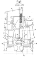
- Figure 1 shows a support device, which is indicated as 10 as a whole, for nozzles 12 of a gas turbine stage, and is interposed in a rotor of the gas turbine itself in order to separate an upstream blading disc 22 from a downstream blading disc 24 of the nozzle 12 itself.
- the nozzles 12 of a gas turbine stage comprise an annular body, which in turn can be divided into nozzle segments 12.
- Each nozzle segment 12 which is connected on the exterior to a gas turbine body 14 by means of segments known as shrouds 16, is supported in its interior by the support device 10.
- This support device 10 comprises a diaphragm-type segment 18, which is connected to the nozzle segments 12 by means of clasps and grooves which are arranged correspondingly on the items, and a honeycomb-type alveolar seal 20, which is provided inside the diaphragm-type segment 18.
- the sealing relative to the rotor blading discs 22 and 24 is obtained by means of foils which are embedded in the diaphragm-type segments 18.
- cooling holes 26 for air which cools the upstream 22 and downstream 24 blading discs.
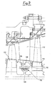
- Figure 2 illustrates a simplified support device according to the present invention, which is indicated as a whole as 110, for nozzles 112 of a gas turbine stage, wherein the components which are the same as/equivalent to those illustrated in figure 1 of the known art have the same reference numbers increased by 100.
- the simplified support device 110 comprises substantially only one honeycomb-type alveolar seal 120.
- This alveolar seal 120 is anchored directly to a lower platform 130 of the nozzle segments 112, without including diaphragm-type segments.
- cooling holes 126 for air which cools the upstream 122 and downstream 124 blading discs.
- the solution with the simplified support device 110 which for example is used for the nozzles 112 of the second stage of a low-pressure gas turbine, is undoubtedly more economical than that with the support device 10 according to the known art, and simultaneously the efficiency of washing of the blading discs 122 and 124 is improved, since the losses caused by blow-by are decreased.
Landscapes
- Engineering & Computer Science (AREA)
- General Engineering & Computer Science (AREA)
- Mechanical Engineering (AREA)
- Chemical & Material Sciences (AREA)
- Combustion & Propulsion (AREA)
- Turbine Rotor Nozzle Sealing (AREA)
- Sealing Using Fluids, Sealing Without Contact, And Removal Of Oil (AREA)
Applications Claiming Priority (2)
| Application Number | Priority Date | Filing Date | Title |
|---|---|---|---|
| IT2002MI001219A ITMI20021219A1 (it) | 2002-06-05 | 2002-06-05 | Dispositivo di supporto semplificato per ugelli di uno stadio di una turbina a gas |
| ITMI20021219 | 2002-06-05 |
Publications (3)
| Publication Number | Publication Date |
|---|---|
| EP1369562A2 EP1369562A2 (en) | 2003-12-10 |
| EP1369562A3 EP1369562A3 (en) | 2007-11-21 |
| EP1369562B1 true EP1369562B1 (en) | 2009-09-09 |
Family
ID=27590461
Family Applications (1)
| Application Number | Title | Priority Date | Filing Date |
|---|---|---|---|
| EP03253530A Expired - Lifetime EP1369562B1 (en) | 2002-06-05 | 2003-06-04 | Support device for nozzles of a gas turbine stage |
Country Status (9)
Families Citing this family (10)
| Publication number | Priority date | Publication date | Assignee | Title |
|---|---|---|---|---|
| US20060095461A1 (en) * | 2004-11-03 | 2006-05-04 | Raymond Robert L | System and method for monitoring a computer environment |
| GB2422641B (en) * | 2005-01-28 | 2007-11-14 | Rolls Royce Plc | Vane for a gas turbine engine |
| US8517666B2 (en) * | 2005-09-12 | 2013-08-27 | United Technologies Corporation | Turbine cooling air sealing |
| JP4764219B2 (ja) * | 2006-03-17 | 2011-08-31 | 三菱重工業株式会社 | ガスタービンのシール構造 |
| FR2923525B1 (fr) * | 2007-11-13 | 2009-12-18 | Snecma | Etancheite d'un anneau de rotor dans un etage de turbine |
| WO2009074355A1 (de) * | 2007-12-10 | 2009-06-18 | Siemens Aktiengesellschaft | Axialturbomaschine mit reduzierten spaltverlusten |
| JP5193960B2 (ja) * | 2009-06-30 | 2013-05-08 | 株式会社日立製作所 | タービンロータ |
| US8327644B2 (en) * | 2009-11-06 | 2012-12-11 | Jhrg Inc. | Micro-turbine combustor |
| US10641117B2 (en) * | 2013-12-12 | 2020-05-05 | United Technologies Corporation | Multiple injector holes for gas turbine engine vane |
| EP3020929A1 (en) * | 2014-11-17 | 2016-05-18 | United Technologies Corporation | Airfoil platform rim seal assembly |
Family Cites Families (19)
| Publication number | Priority date | Publication date | Assignee | Title |
|---|---|---|---|---|
| US3275294A (en) * | 1963-11-14 | 1966-09-27 | Westinghouse Electric Corp | Elastic fluid apparatus |
| US3529905A (en) * | 1966-12-12 | 1970-09-22 | Gen Motors Corp | Cellular metal and seal |
| JPS58197404A (ja) * | 1982-05-14 | 1983-11-17 | Hitachi Ltd | ガスタ−ビンノズル翼 |
| US4526508A (en) * | 1982-09-29 | 1985-07-02 | United Technologies Corporation | Rotor assembly for a gas turbine engine |
| US4416457A (en) * | 1983-01-24 | 1983-11-22 | Westinghouse Electric Corp. | Grooved honeycomb labyrinth seal for steam turbines |
| FR2552159B1 (fr) | 1983-09-21 | 1987-07-10 | Snecma | Dispositif de liaison et d'etancheite de secteurs d'aubes de stator de turbine |
| US5197281A (en) * | 1990-04-03 | 1993-03-30 | General Electric Company | Interstage seal arrangement for airfoil stages of turbine engine counterrotating rotors |
| US5176496A (en) * | 1991-09-27 | 1993-01-05 | General Electric Company | Mounting arrangements for turbine nozzles |
| US5215435A (en) * | 1991-10-28 | 1993-06-01 | General Electric Company | Angled cooling air bypass slots in honeycomb seals |
| US5320483A (en) * | 1992-12-30 | 1994-06-14 | General Electric Company | Steam and air cooling for stator stage of a turbine |
| US5358374A (en) * | 1993-07-21 | 1994-10-25 | General Electric Company | Turbine nozzle backflow inhibitor |
| JPH07139305A (ja) * | 1993-11-16 | 1995-05-30 | Mitsubishi Heavy Ind Ltd | ラビリンスシール固定構造 |
| JP3327814B2 (ja) * | 1997-06-18 | 2002-09-24 | 三菱重工業株式会社 | ガスタービンのシール装置 |
| JP3887469B2 (ja) * | 1997-11-28 | 2007-02-28 | 株式会社東芝 | ガスタービンプラント |
| US6065928A (en) * | 1998-07-22 | 2000-05-23 | General Electric Company | Turbine nozzle having purge air circuit |
| JP2000230405A (ja) * | 1999-02-09 | 2000-08-22 | Ishikawajima Harima Heavy Ind Co Ltd | タービン静翼先端部シール |
| US6183192B1 (en) * | 1999-03-22 | 2001-02-06 | General Electric Company | Durable turbine nozzle |
| US6398488B1 (en) * | 2000-09-13 | 2002-06-04 | General Electric Company | Interstage seal cooling |
| US6769865B2 (en) * | 2002-03-22 | 2004-08-03 | General Electric Company | Band cooled turbine nozzle |
-
2002
- 2002-06-05 IT IT2002MI001219A patent/ITMI20021219A1/it unknown
-
2003
- 2003-05-29 CA CA2430444A patent/CA2430444C/en not_active Expired - Fee Related
- 2003-06-03 US US10/452,900 patent/US6857847B2/en not_active Expired - Fee Related
- 2003-06-04 KR KR1020030035872A patent/KR101013263B1/ko not_active Expired - Fee Related
- 2003-06-04 EP EP03253530A patent/EP1369562B1/en not_active Expired - Lifetime
- 2003-06-04 DE DE60329142T patent/DE60329142D1/de not_active Expired - Lifetime
- 2003-06-04 NO NO20032527A patent/NO20032527L/no not_active Application Discontinuation
- 2003-06-05 JP JP2003160216A patent/JP2004028096A/ja active Pending
- 2003-06-05 CN CN2011102827087A patent/CN102425460A/zh active Pending
- 2003-06-05 CN CNA031472168A patent/CN1495339A/zh active Pending
Also Published As
| Publication number | Publication date |
|---|---|
| US6857847B2 (en) | 2005-02-22 |
| KR20030094108A (ko) | 2003-12-11 |
| KR101013263B1 (ko) | 2011-02-09 |
| ITMI20021219A1 (it) | 2003-12-05 |
| EP1369562A3 (en) | 2007-11-21 |
| NO20032527L (no) | 2003-12-08 |
| DE60329142D1 (de) | 2009-10-22 |
| CA2430444A1 (en) | 2003-12-05 |
| US20040033132A1 (en) | 2004-02-19 |
| CA2430444C (en) | 2010-02-16 |
| CN1495339A (zh) | 2004-05-12 |
| NO20032527D0 (no) | 2003-06-04 |
| EP1369562A2 (en) | 2003-12-10 |
| JP2004028096A (ja) | 2004-01-29 |
| CN102425460A (zh) | 2012-04-25 |
Similar Documents
| Publication | Publication Date | Title |
|---|---|---|
| US9423130B2 (en) | Reverse flow ceramic matrix composite combustor | |
| CA2532704C (en) | Gas turbine engine shroud sealing arrangement | |
| EP2075437B1 (en) | Multi-source gas turbine cooling | |
| US20150292438A1 (en) | Method and apparatus for cooling combustor liner in combustor | |
| US8137075B2 (en) | Compressor impellers, compressor sections including the compressor impellers, and methods of manufacturing | |
| US20030145604A1 (en) | Double wall combustor tile arrangement | |
| US20180306120A1 (en) | Pressure regulated piston seal for a gas turbine combustor liner | |
| US5205706A (en) | Axial flow turbine assembly and a multi-stage seal | |
| US11976562B2 (en) | System for controlling blade clearances within a gas turbine engine | |
| EP1369562B1 (en) | Support device for nozzles of a gas turbine stage | |
| US11725817B2 (en) | Combustor assembly with moveable interface dilution opening | |
| EP1217231B1 (en) | Bolted joint for rotor disks and method of reducing thermal gradients therein | |
| EP2519719A2 (en) | Gas turbine engine having dome panel assembly with bifurcated swirler flow | |
| EP1576258A1 (en) | Shroud cooling assembly for a gas turbine | |
| US20160160667A1 (en) | Discourager seal for a turbine engine | |
| KR102566946B1 (ko) | 씰링 어셈블리 및 이를 포함하는 터보머신 | |
| US11821365B2 (en) | Inducer seal with integrated inducer slots | |
| CA2580476C (en) | Structure for separating the internal areas of a high pressure and a low pressure turbine |
Legal Events
| Date | Code | Title | Description |
|---|---|---|---|
| PUAI | Public reference made under article 153(3) epc to a published international application that has entered the european phase |
Free format text: ORIGINAL CODE: 0009012 |
|
| AK | Designated contracting states |
Kind code of ref document: A2 Designated state(s): AT BE BG CH CY CZ DE DK EE ES FI FR GB GR HU IE IT LI LU MC NL PT RO SE SI SK TR |
|
| AX | Request for extension of the european patent |
Extension state: AL LT LV MK |
|
| PUAL | Search report despatched |
Free format text: ORIGINAL CODE: 0009013 |
|
| AK | Designated contracting states |
Kind code of ref document: A3 Designated state(s): AT BE BG CH CY CZ DE DK EE ES FI FR GB GR HU IE IT LI LU MC NL PT RO SE SI SK TR |
|
| AX | Request for extension of the european patent |
Extension state: AL LT LV MK |
|
| 17P | Request for examination filed |
Effective date: 20080521 |
|
| 17Q | First examination report despatched |
Effective date: 20080618 |
|
| AKX | Designation fees paid |
Designated state(s): CH DE FR GB IT LI NL |
|
| GRAC | Information related to communication of intention to grant a patent modified |
Free format text: ORIGINAL CODE: EPIDOSCIGR1 |
|
| GRAP | Despatch of communication of intention to grant a patent |
Free format text: ORIGINAL CODE: EPIDOSNIGR1 |
|
| GRAS | Grant fee paid |
Free format text: ORIGINAL CODE: EPIDOSNIGR3 |
|
| GRAA | (expected) grant |
Free format text: ORIGINAL CODE: 0009210 |
|
| AK | Designated contracting states |
Kind code of ref document: B1 Designated state(s): CH DE FR GB IT LI NL |
|
| REG | Reference to a national code |
Ref country code: GB Ref legal event code: FG4D |
|
| REG | Reference to a national code |
Ref country code: CH Ref legal event code: EP |
|
| REG | Reference to a national code |
Ref country code: CH Ref legal event code: NV Representative=s name: SERVOPATENT GMBH |
|
| REF | Corresponds to: |
Ref document number: 60329142 Country of ref document: DE Date of ref document: 20091022 Kind code of ref document: P |
|
| PLBE | No opposition filed within time limit |
Free format text: ORIGINAL CODE: 0009261 |
|
| STAA | Information on the status of an ep patent application or granted ep patent |
Free format text: STATUS: NO OPPOSITION FILED WITHIN TIME LIMIT |
|
| 26N | No opposition filed |
Effective date: 20100610 |
|
| PGFP | Annual fee paid to national office [announced via postgrant information from national office to epo] |
Ref country code: GB Payment date: 20130627 Year of fee payment: 11 Ref country code: DE Payment date: 20130627 Year of fee payment: 11 Ref country code: CH Payment date: 20130627 Year of fee payment: 11 |
|
| PGFP | Annual fee paid to national office [announced via postgrant information from national office to epo] |
Ref country code: FR Payment date: 20130702 Year of fee payment: 11 Ref country code: IT Payment date: 20130624 Year of fee payment: 11 |
|
| PGFP | Annual fee paid to national office [announced via postgrant information from national office to epo] |
Ref country code: NL Payment date: 20130626 Year of fee payment: 11 |
|
| REG | Reference to a national code |
Ref country code: DE Ref legal event code: R119 Ref document number: 60329142 Country of ref document: DE |
|
| REG | Reference to a national code |
Ref country code: NL Ref legal event code: V1 Effective date: 20150101 |
|
| REG | Reference to a national code |
Ref country code: CH Ref legal event code: PL |
|
| GBPC | Gb: european patent ceased through non-payment of renewal fee |
Effective date: 20140604 |
|
| REG | Reference to a national code |
Ref country code: FR Ref legal event code: ST Effective date: 20150227 |
|
| PG25 | Lapsed in a contracting state [announced via postgrant information from national office to epo] |
Ref country code: NL Free format text: LAPSE BECAUSE OF NON-PAYMENT OF DUE FEES Effective date: 20150101 |
|
| REG | Reference to a national code |
Ref country code: DE Ref legal event code: R119 Ref document number: 60329142 Country of ref document: DE Effective date: 20150101 |
|
| PG25 | Lapsed in a contracting state [announced via postgrant information from national office to epo] |
Ref country code: DE Free format text: LAPSE BECAUSE OF NON-PAYMENT OF DUE FEES Effective date: 20150101 Ref country code: IT Free format text: LAPSE BECAUSE OF NON-PAYMENT OF DUE FEES Effective date: 20140604 Ref country code: LI Free format text: LAPSE BECAUSE OF NON-PAYMENT OF DUE FEES Effective date: 20140630 Ref country code: CH Free format text: LAPSE BECAUSE OF NON-PAYMENT OF DUE FEES Effective date: 20140630 |
|
| PG25 | Lapsed in a contracting state [announced via postgrant information from national office to epo] |
Ref country code: GB Free format text: LAPSE BECAUSE OF NON-PAYMENT OF DUE FEES Effective date: 20140604 Ref country code: FR Free format text: LAPSE BECAUSE OF NON-PAYMENT OF DUE FEES Effective date: 20140630 |