EP1369529A1 - Systeme et procede de remplacement de ballast d'assiette de voie de chemin de fer - Google Patents
Systeme et procede de remplacement de ballast d'assiette de voie de chemin de fer Download PDFInfo
- Publication number
- EP1369529A1 EP1369529A1 EP01912272A EP01912272A EP1369529A1 EP 1369529 A1 EP1369529 A1 EP 1369529A1 EP 01912272 A EP01912272 A EP 01912272A EP 01912272 A EP01912272 A EP 01912272A EP 1369529 A1 EP1369529 A1 EP 1369529A1
- Authority
- EP
- European Patent Office
- Prior art keywords
- ballast
- car
- working
- load carrying
- new
- Prior art date
- Legal status (The legal status is an assumption and is not a legal conclusion. Google has not performed a legal analysis and makes no representation as to the accuracy of the status listed.)
- Granted
Links
Images


Classifications
-
- E—FIXED CONSTRUCTIONS
- E01—CONSTRUCTION OF ROADS, RAILWAYS, OR BRIDGES
- E01B—PERMANENT WAY; PERMANENT-WAY TOOLS; MACHINES FOR MAKING RAILWAYS OF ALL KINDS
- E01B27/00—Placing, renewing, working, cleaning, or taking-up the ballast, with or without concurrent work on the track; Devices therefor; Packing sleepers
- E01B27/06—Renewing or cleaning the ballast in situ, with or without concurrent work on the track
- E01B27/10—Renewing or cleaning the ballast in situ, with or without concurrent work on the track without taking-up track
-
- E—FIXED CONSTRUCTIONS
- E01—CONSTRUCTION OF ROADS, RAILWAYS, OR BRIDGES
- E01B—PERMANENT WAY; PERMANENT-WAY TOOLS; MACHINES FOR MAKING RAILWAYS OF ALL KINDS
- E01B27/00—Placing, renewing, working, cleaning, or taking-up the ballast, with or without concurrent work on the track; Devices therefor; Packing sleepers
Definitions
- the present invention relates to a system and method for exchanging ballast at a railroad bed which is laid under rail support ties.
- a railroad track has a railroad bed for allowing car loads borne on the railroad ties to be distributed onto the railroad bed.
- This kind of railroad bed is comprised of layered ballast and there is a need for such ballast to be exchanged, as required, so as to maintain the railroad track.
- a ballast exchange method there are conventionally known a first working method as shown in FIG. 5 and a second working method as shown in FIG. 8.
- a first working train 1 for scraping up the already laid ballast B and a second working train 2 for carrying new ballast NB for exchange are prepared.
- the first and second working trains 1 and 2 are each made up of an independent one-line unit system and wait on the same tracks for maintenance to be done.
- the first working train 1 comprises a ballast working car 4 for scraping up the already laid ballast B, a plurality of hopper cars 5a, 5b for allowing the scraped-up ballast B to be loaded thereon, and a track motor car 6 for hauling the ballast working car 4 and hopper cars 5a, 5b and running at low speeds.
- the ballast working car 4 is located at the rearmost position of the first working train 1.
- a ballast scraping-up device 8 is mounted at the rearmost end of the ballast working car 4.
- the ballast scraping-up device 8 is equipped with a cutter 11 guided beneath many ties 10 supporting two rails 9a, 9b.
- the cutter 11 comprises an endless-like cutter link unit 12 and many scrapers 13 arranged at intervals along the side surface of the cutter link unit 12.
- the cutter link unit 12 extends in a direction orthogonal to the rails 9a, 9b in a position below the ties 10 and is rotationally and continuously driven in an arrow direction by means of a motor 14. IN this way, the ballast B beneath the ties 10 is scraped out toward the lateral side of the rails 9a, 9b.
- ballast B which is scraped up by the ballast scraping-up device 8 is conveyed by a first out conveyor 15 onto the upper side of the ballast working car 4 and from there onto the rearmost hopper car 5b through a second out conveyor 16.
- the hopper cars 5a and 5b each have a loading space 18 for allowing the ballast B to be loaded thereon.
- main conveyors 19a and 19b and feed-out conveyors 20a and 20b are located, respectively.
- the main conveyors 19a and 19b are located at the bottoms of the loading spaces 18 and horizontally extend along the running direction of the hopper cars 5a and 5b.
- the feed-out conveyors 20a and 20b are located at the discharge ends of the main conveyors 19a and 19b.
- the feed-out conveyor 20b of the rear hopper car 5b is situated astride relative to the loading space 18 of the front hopper car 5a.
- the ballast B which has been scraped up by means of the ballast scraping-up device 8 is fed through the first and second out conveyors 15 and 16 onto the loading space 18 of the rearmost hopper car 5b.
- the ballast B is sequentially fed through the main conveyor 19b and feed-out conveyor 20b into the loading space 18 of the front hopper car 5a.
- the second working train 2 comprises a plurality of hopper cars 23a, 23b and a track motor car 24 for propelling these hopper cars 23a, 23b toward the dug-up site 21 set out above.
- the hopper cars 23a and 23b have loading spaces 25 where new ballast NB has been loaded for exchange.
- Main conveyors 26a and 26b and feed-out conveyors 27a and 27b are located at loading spaces 25 of the hopper cars 23a and 23b, respectively.
- the main conveyors 26a and 26b are located at the bottoms of the loading spaces 25 and horizontally extend along the running direction of the hopper cars 23a and 23b.
- the feed-out conveyors 27a and 27b are located at the discharge ends of the main conveyors 26a and 26b.
- the feed-out conveyor 27b of the back hopper car 23b is situated astride the loading space 25 of the front hopper car 23a.
- the second working train 2 is moved toward the dug-up site 21 after the scraping-up operation of the ballast B by the first working train 1 has been done.
- new ballast NB which has been loaded in the loading space 25 is unloaded into the dug-up site 21 through the feed-out conveyor 27a of the front hopper car 23a.
- the new ballast NB loaded in the loading space 25 of the rear hopper 23b is sequentially fed through the main conveyor 26b and feed-out conveyor 27b into the loading space 25 of the front hopper car 23a and from there into the dug-up site 21 through the feed-out conveyor 27a.
- a first working train 31 for scraping up already laid ballast B, a second working train 32 for loading the scraped-up ballast B therein and a third working train 33 with new ballast NB loaded therein for exchange are prepared.
- the first, second and third working trains 31 to 33, are each organized into an independent one-line unit system.
- the first working train 31 and third working train 33 wait on the same tracks 34 for maintenance to be done there and the second working train 32 waits on the adjacent track 35.
- the first working train 31 comprises a ballast working car 37 for scraping up the ballast B and a track motor car 6 hauling the ballast working car 37 and running at low speed.
- the ballast working car 37 has a ballast scraping-up device 8 of the same type as used in the first working method set out above, a first out conveyor 15 and a second out conveyor 16.
- the ballast scraping-up device 8 is provided at the front end of the ballast working car 37 and located opposite to the track motor car 6 for traction.
- the ballast B which has been scraped up by means of the ballast scraping-up device 8 is fed from the first out conveyor 15 through the second out conveyor 16 onto the waiting second working train 32 on the adjacent track 35.
- the second working train 32 comprises a plurality of mutually coupled trucks 38a to 38c and two track motor cars 39a, 39b coupled together one at the front and one at the rear.
- the trucks 38a to 38c each have an empty loading space 40 and the ballast B which is scraped up is loaded through the second out conveyor 16 into the empty loading space 40.
- the third working train 33 comprises a plurality of mutually coupled hopper cars 42a to 42c and two track motor cars 43a, 43b coupled together one at the front and one at the rear.
- the hopper cars 42a, ⁇ , 42c have a loading space 44 equipped with a hopper function and new ballast NB is loaded into the loading space 44.
- the third working train 33 is moved to the dug-up site 21 where new ballast NB is unloaded from the loading space 44 of the hopper cars 42a to 42c.
- the ballast scraping-up device 8 is located at the front end of the ballast working car 37 and, with an advance of the ballast scraping-up operation, the ballast working car 37 passes over the dug-up site 21.
- a worker walks into the dug-up site 21 after the ballast scraping-up operation and it is necessary to insert many tie support bases 46 beneath floated ties 10 as shown in FIG. 7. By doing so, the tie 10 is supported on the tie support base 46 so that the rails 9a, 9b are prevented from sunking under the weight of the ballast working car 37.
- the second working train 2 with new ballast NB loaded thereon is moved to the dug-up site 21 at the track 3 after the ballast scraping-up operation by the first working train 1 has ended, and it takes a lot of time to switch the working trains from one track to another track and it also takes a long time to perform a ballast exchange operation.
- the trucks 38a to 38c need to wait for ballast B which has been scraped up by the ballast working car 37 to be loaded therein on the track 35 situated adjacent to the track 34 to allow maintenance to be done. It is, therefore, necessary to block the two adjacent tracks 34 and 35 for such maintenance to be done, which may involve some inconvenience in the running of trains.
- the worker walks into the dug-up site 21 where the ballast B has been scraped up, and it is necessary to mount the tie support bases 46 manually beneath the ties 10. It is also necessary to manually remove the tie support bases 46 from the dug-up site 21 prior to the unloading of the new ballast NB into the dug-up site 21.
- the first to third working trains 31 to 33 need to be run individually and a ballast exchange operation becomes greater in scale. For this reason, many more workers are required than in the first working method and there arises a greater labor cost problem.
- the third working train 33 with new ballast NB loaded therein is moved toward the dug-up site 21 at the track 34 after the ballast scraping-up operation by the first working train 31 has ended. Therefore, a greater time is required as in the first working method to switch the first and third working trains 31 and 33 from one track to another and it is not possible to perform a ballast exchange operation efficiently.
- the present invention is achieved with the above-mentioned situations in view and it is accordingly the object of the present invention to provide a ballast exchanging system and method for a railroad bed which can efficiently and positively perform a ballast exchanging operation while reducing the number of workers and cars involved in the ballast exchanging operation and can reduce the ballast exchanging time involved.
- a ballast exchanging system for a railroad bed comprising a working train formed as a one-line unit system having a plurality of load carrying cars coupled together with new ballast loaded thereon for exchange and a ballast working car coupled to a rearmost load carrying car and having collecting means configured to scrape up ballast which has already been laid under the railroad.
- the ballast working car has out-conveying means configured to convey the ballast which is scraped up by the collecting means toward the rearmost load carrying car and unloading means configured to unload the new ballast into a dug-up site where the laid ballast has been scraped up, and the load carrying cars have first conveying means configured to sequentially convey the ballast which is conveyed through the out-conveying means from the rearmost load carrying car toward a forwardmost load carrying car and second conveying means configured to convey the loaded new ballast to the unloading means of the ballast working car via the rearmost load carrying car.
- a ballast exchanging method comprising a step of, while allowing the ballast which is scraped up by the collecting means of the ballast collecting car to be sequentially conveyed from a rearmost load carrying car toward a forwardmost load carrying car, supplying the new ballast which is loaded on the load carrying car to the unloading means of the ballast working car via the rearmost load carrying car and a step of allowing the scraped-up ballast to be replaced by the new ballast, for exchange, which is loaded in the working train of a one-line unit system.
- FIG. 1 is a view diagrammatically showing a working train 51 for use in the replacement of ballast B under railroad ties 10 by new ballast.
- the working train 51 comprises a ballast working car 52, five hopper cars 53a to 53e serving as load carrying cars, and two track motor cars 54a, 54b for hauling the ballast working car 52 and hopper cars 53a to 53e.
- the ballast working car 52, hopper cars 53a to 53e and track motor cars 54a, 54b are coupled into a one-line unit system and wait on a track 50 for maintenance to be done.
- the ballast working car 52 is located at the rearmost end of the working train 51.
- the ballast working car 52 has a ballast scraping-up device 56 serving as a ballast collecting means, and first and second out-conveyors 57a, 57b serving as out-conveying means.
- the ballast scraping-up device 56 is provided at the rear end of the ballast working car 52.
- the ballast scraping-up device 56 has a structure similar to that of the above-mentioned conventional ballast scraping-up device 8 and its detailed explanation is omitted.
- the ballast B scraped up by the ballast scraping-up device 56 is conveyed through the first out-conveyor 57a onto the upper side of the ballast working car 52 where it is fed from the first out-conveyor 57a onto the second out-conveyor 57b.
- the second out-conveyor 57b extends toward the rearmost hopper car 53e above the ballast working car 52.
- the ballast working car 52 has an unloading conveyor 58 serving as an unloading means.
- the unloading conveyor 58 is located below the second out-conveyor 57b and situated substantially horizontally along a running direction of the ballast working card 52.
- a discharge end 58a of the unloading conveyor 58 is projected more rearwardly than the first out-conveyor 57a above the ballast scraping-up device 56.
- the hopper cars 53a to 53e each, have a loading space 60.
- the loading space 60 of the forwardmost hopper car 53a is set in an empty state so as to allow the scraped-up ballast B to be loaded therein.
- new ballast NB is loaded for exchange.
- a first belt conveyor 61 is provided as a first conveying means and second and third belt conveyors 62 and 63 are provided as second conveying means.
- the first belt conveyor 61 comprises a receiving conveyor 61a and a discharging conveyor 61b. These conveyors 61a, 61b are set by a plurality of stays 64 above the loading space 60. And the conveyors 61a and 61b are arranged in one row above the loading space 60 and driven toward a front side from the rear side of the working train 51.
- the receiving conveyor 61a and discharging conveyor 61b are upwardly tilted from the receiving side toward the discharging side along the conveying direction of the ballast B.
- the receiving end of the discharging conveyor 61b is situated below the discharging end of the receiving conveyor 61a.
- the discharging end of the discharging conveyor 61b is situated above the receiving end of the receiving conveyor 61a.
- the receiving end of the receiving conveyor 61a is situated below the discharge end of the second out-conveyor 57b of the ballast working car 52.
- the ballast B scraped up by the ballast scraping-up device 56 is fed from the second out-conveyor 57b onto the first belt conveyor 61 of the rearmost hopper car 53e.
- the ballast B is conveyed sequentially through the first belt conveyor 61 of the hopper cars 53a to 53d into the loading space 60 of the forwardmost hopper car 53a.
- the second belt conveyor 62 is located at the bottom portion of the loading space 60 and horizontally extends along the running direction of the hopper cars 53a to 53e.
- the second belt conveyor 62 is driven from the front side of the working train 51 toward the rear side.
- the discharging end of the respective second belt conveyor 62 is located at the back side of the loading space 60 of the respective hopper cars 53a to 53e.
- the third belt conveyor 63 extends in an upwardly tilted direction from the back of the loading space 60 rearwardly.
- the third belt conveyor 63 is driven from the forward side of the working train 51 toward the rear side in a way to follow the second belt conveyor 62.
- the discharge end of the third belt conveyor 63 is located above the forward portion of the loading space 60 of the rear hopper cars 53b to 53e.
- the discharging end of the third belt conveyor 63 is located above the receiving end 58b of the above-mentioned unloading conveyor 58.
- new ballast NB loaded into the loading space 60 is sequentially sent through the second and third belt conveyors 62 and 63 into the loading space 60 of the rearmost hopper car 53e and from there onto the unloading conveyor 58 of the ballast working car 52.
- the track motor cars 54a and 54b are located at the forwardmost side of the working train 51 and haul the ballast working car 52 and hopper cars 53a to 53e at a given speed by means of a low-speed running device not shown. For this reason, the working train 51 is moved at a low speed in a direction away from a dug-up site 21 where the ballast B has been scraped up.
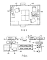
- the track motor cars 54a and 54b each include a crew attended cabin 65. As shown in FIG. 3, the cabin 65 has an operation room 66 and central monitoring room 67.
- the central monitoring room 67 has a plurality of monitors 68.
- the monitors 68 display the scraping-up state of the ballast B, unloading state of the new ballast NB, conveying state of the ballast B sent on the first belt conveyor 61 and conveying state of the new ballast NB sent on the second belt conveyor 62.
- a color camera 70 is set on the rear end of the ballast working car 52 to photograph the scraping-up state of the ballast B and unloading state of the new ballast NB.
- a color camera 71 is set at the discharge end of the discharging conveyor 61b of the respective hopper cars 53a to 53e to photograph the loading space 60 from above.
- the video signals taken by the color cameras 70, 71 are sent to a control unit 72 for image division and to a transmit/receive unit 74 via a controller 73 and transmitted from an antenna 75 of the transmit/ receive unit 74.
- a light illumination unit 76 (see FIG. 4) is set on the rear end of the ballast working car 52 and on the loading space 60 of the respective hopper cars 53a to 53e.
- the light illumination unit 76 illuminates a ballast scraping-up site and a conveying path of the ballast B. By doing so it is possible to secure a uniform illumination of an object.
- the monitors 68 of the central monitoring room 67 are connected through a controller 78 to a transmit/receive unit 79.
- the transmit/receive unit 79 has an antenna 80.
- the antenna 80 receives a video signal transmitted from the antenna 75 of the transmit/receive unit 74.
- the scraping-up state of the ballast B, unloading state of the new ballast NB, and conveying states of the ballast B and new ballast NB are displayed as video images on the monitors 68.
- the monitor 68 includes a liquid crystal display 80 having a four-segmented image screen and a touch panel type operation display 81.
- the operation display 81 has a finger actuated image screen and, upon finger actuation, an image on the screen of the liquid crystal display 80 can be switched.
- the working train 51 waiting on the track 50 is moved to a location for maintenance to be done.
- the ballast scraping-up device 56 of the ballast working car 52 is driven to cause it to slide beneath the ties 10 from the lateral sides of the rails 9a, 9b.
- the working train 51 is forwardly moved at low speeds to allow the ballast B which has already been laid beneath the railroad ties 10 to be sequentially scraped up.
- the scraped-up ballast B is conveyed through the first and second out-conveyor 57a and 57b onto the first belt conveyor 61 of the rearmost hopper car 53e and from there past the first conveyors 61 of these hopper cars 53d to 53b onto the loading space 60 of the forwardmost hopper car 53a. In this way, the scraped-up ballast B is once loaded into the loading space 60 of the forwardmost hopper car 53a.
- the new ballast NB loaded in the rearmost hopper car 53e is transported onto the unloading conveyor 58 of the ballast working car 52 through the corresponding second and third belt conveyors 62 and 63, which at the same time the ballast B is scraped up.
- the new ballast NB is unloaded through the unloading conveyor 58 into the dug-up site 21 where the ballast B has been scraped up.
- the new ballast NB loaded in the intermediate hopper cars 53b to 53d is conveyed toward a sequentially rearward hopper cars 53c to 53e through the corresponding second and third belt conveyors 62 and 63 in the respective loading spaces 60. By doing so, the new ballast NB is unloaded into the dug-up site 21 from the unloading conveyor 58 of the ballast working car 52.
- the ballast B which has been conveyed into the loading space 60 of the forwardmost hopper 53a is conveyed onto the sequentially rearward hopper cars 53b, ⁇ , 53e through the corresponding second and third belt conveyors 62 and 63.
- the new ballast NB is conveyed from the loading space 60 of the hopper cars 53b, ⁇ , 53e, while at the same time the scraped-up ballast B is loaded into that loading space 60 involved.
- the scraping-up state of the ballast B, unloading state of the new ballast NB, and conveying states of the ballast B and new ballast NB are photographed by means of color cameras 70 and 71.
- Those video signals from the color cameras 70 and 71 are transferred to the central monitoring room 67 of the track motor cars 54a, 54b where they are displayed on the monitors 68.
- ballast exchanging method it is possible to scrape up the ballast B under the railroad ties 10 while, at the same time, unloading the new ballast NB loaded on the hopper cars 53b to 53e into the dug-up site 21 where the ballast B has been scraped up. After the already laid ballast B has been scraped up, it is possible to promptly shift a working phase to a track maintenance phase with the use of the new ballast NB. It is, therefore, possible to promptly perform the ballast exchanging operation, while suppressing any warp on the track 50 to a minimal extent.
- ballast scraping-up device 56 is provided at the rear end of the ballast working car 52 and, in addition, the working train 51 is moved in a direction away from the dug-up site 21 where the laid ballast B has been scraped up, there occurs no running of the heavy working train 51 over the dug-up site 21. It is also not necessary to perform any cumbersome work by inserting the tie support bases at the dug-up site 21 and removing the tie support bases at a time of unloading the new ballast NB into the dug-up site. It is possible to suppress the working steps of the maintenance to a minimal extent and reduce the working time involved.
- the working train 51 is constructed of a one-line unit system and, in comparison with the conventional second working method in particular, it is possible to reduce the number of the track motor cars 54a, 54b and hopper cars 53a to 53e as well as the number of workers on the running of the working train 51. Therefore, any larger-scale of working with the adjacent two tracks closed is unnecessary and the ballast exchanging cost can be reduced.
- ballast exchanging operation can be efficiently done in a shorter time without any hindrance to the running of railroad trains and it is possible to reduce the cost involved in the ballast exchange.
Landscapes
- Engineering & Computer Science (AREA)
- Architecture (AREA)
- Civil Engineering (AREA)
- Structural Engineering (AREA)
- Machines For Laying And Maintaining Railways (AREA)
- Train Traffic Observation, Control, And Security (AREA)
- Circuits Of Receivers In General (AREA)
- Golf Clubs (AREA)
Applications Claiming Priority (1)
| Application Number | Priority Date | Filing Date | Title |
|---|---|---|---|
| PCT/JP2001/001916 WO2002072958A1 (fr) | 2001-03-12 | 2001-03-12 | Systeme et procede de remplacement de ballast d'assiette de voie de chemin de fer |
Publications (3)
| Publication Number | Publication Date |
|---|---|
| EP1369529A1 true EP1369529A1 (fr) | 2003-12-10 |
| EP1369529A4 EP1369529A4 (fr) | 2004-05-26 |
| EP1369529B1 EP1369529B1 (fr) | 2006-06-14 |
Family
ID=11737112
Family Applications (1)
| Application Number | Title | Priority Date | Filing Date |
|---|---|---|---|
| EP01912272A Revoked EP1369529B1 (fr) | 2001-03-12 | 2001-03-12 | Systeme et procede de remplacement de ballast d'assiette de voie de chemin de fer |
Country Status (5)
| Country | Link |
|---|---|
| EP (1) | EP1369529B1 (fr) |
| AT (1) | ATE330069T1 (fr) |
| DE (1) | DE60120778T2 (fr) |
| ES (1) | ES2265416T3 (fr) |
| WO (1) | WO2002072958A1 (fr) |
Cited By (3)
| Publication number | Priority date | Publication date | Assignee | Title |
|---|---|---|---|---|
| EP1775190A3 (fr) * | 2005-10-17 | 2007-06-20 | VolkerRail Nederland BV | Renouvellement du lit de ballast d'une voie ferrée |
| FR2897326A1 (fr) * | 2006-02-16 | 2007-08-17 | Europ De Travaux Ferroviaires | Procede et dispositif pour l'optimisation de l'agencement des elements constitutifs de trains dits de "travaux" |
| EP2708648A3 (fr) * | 2012-09-12 | 2016-04-20 | Zuercher Holding GmbH | Dispositif destiné à la réalisation et/ou à la rénovation d'une voie ferrée |
Families Citing this family (2)
| Publication number | Priority date | Publication date | Assignee | Title |
|---|---|---|---|---|
| DE102007026310B3 (de) * | 2007-06-06 | 2008-08-07 | Ralf Zürcher | Vorrichtung zur Materialförderung im Gleisbau |
| AU2014286912A1 (en) * | 2013-07-03 | 2016-01-28 | Murphy Pipe & Civil IP Pty Ltd | A pipeline padder |
Citations (4)
| Publication number | Priority date | Publication date | Assignee | Title |
|---|---|---|---|---|
| FR2238804A1 (en) * | 1973-07-27 | 1975-02-21 | Seco | System of handling old railway ballast - uses a train of wagons on which are mounted conveyor belts |
| DE2713634A1 (de) * | 1976-05-31 | 1977-12-22 | Plasser Bahnbaumasch Franz | Fahrbare maschinenanordnung zum transport von schuettgut |
| JPH03233001A (ja) * | 1990-02-08 | 1991-10-17 | Higashi Nippon Riyokaku Tetsudo Kk | 道床交換システム |
| JP2000257004A (ja) * | 1999-03-12 | 2000-09-19 | Hosen Kiki Seibi Kk | 道床更新工事の砕石取り替え装置 |
Family Cites Families (2)
| Publication number | Priority date | Publication date | Assignee | Title |
|---|---|---|---|---|
| DK0824164T3 (da) * | 1996-08-14 | 2004-06-28 | Plasser Bahnbaumasch Franz | Sporbygningsmaskine til udgravning af ballastmateriale i et spor |
| JP3794878B2 (ja) * | 1999-09-13 | 2006-07-12 | 三菱重工業株式会社 | 鉄道用道床バラスト交換システムおよびバラスト交換方法 |
-
2001
- 2001-03-12 DE DE60120778T patent/DE60120778T2/de not_active Expired - Lifetime
- 2001-03-12 ES ES01912272T patent/ES2265416T3/es not_active Expired - Lifetime
- 2001-03-12 EP EP01912272A patent/EP1369529B1/fr not_active Revoked
- 2001-03-12 AT AT01912272T patent/ATE330069T1/de active
- 2001-03-12 WO PCT/JP2001/001916 patent/WO2002072958A1/fr active IP Right Grant
Patent Citations (4)
| Publication number | Priority date | Publication date | Assignee | Title |
|---|---|---|---|---|
| FR2238804A1 (en) * | 1973-07-27 | 1975-02-21 | Seco | System of handling old railway ballast - uses a train of wagons on which are mounted conveyor belts |
| DE2713634A1 (de) * | 1976-05-31 | 1977-12-22 | Plasser Bahnbaumasch Franz | Fahrbare maschinenanordnung zum transport von schuettgut |
| JPH03233001A (ja) * | 1990-02-08 | 1991-10-17 | Higashi Nippon Riyokaku Tetsudo Kk | 道床交換システム |
| JP2000257004A (ja) * | 1999-03-12 | 2000-09-19 | Hosen Kiki Seibi Kk | 道床更新工事の砕石取り替え装置 |
Non-Patent Citations (3)
| Title |
|---|
| PATENT ABSTRACTS OF JAPAN vol. 016, no. 010 (M-1199), 13 January 1992 (1992-01-13) & JP 03 233001 A (HIGASHI NIPPON RIYOKAKU TETSUDO KK;OTHERS: 01), 17 October 1991 (1991-10-17) * |
| PATENT ABSTRACTS OF JAPAN vol. 2000, no. 12, 3 January 2001 (2001-01-03) & JP 2000 257004 A (HOSEN KIKI SEIBI KK), 19 September 2000 (2000-09-19) * |
| See also references of WO02072958A1 * |
Cited By (3)
| Publication number | Priority date | Publication date | Assignee | Title |
|---|---|---|---|---|
| EP1775190A3 (fr) * | 2005-10-17 | 2007-06-20 | VolkerRail Nederland BV | Renouvellement du lit de ballast d'une voie ferrée |
| FR2897326A1 (fr) * | 2006-02-16 | 2007-08-17 | Europ De Travaux Ferroviaires | Procede et dispositif pour l'optimisation de l'agencement des elements constitutifs de trains dits de "travaux" |
| EP2708648A3 (fr) * | 2012-09-12 | 2016-04-20 | Zuercher Holding GmbH | Dispositif destiné à la réalisation et/ou à la rénovation d'une voie ferrée |
Also Published As
| Publication number | Publication date |
|---|---|
| EP1369529B1 (fr) | 2006-06-14 |
| WO2002072958A1 (fr) | 2002-09-19 |
| ES2265416T3 (es) | 2007-02-16 |
| DE60120778T2 (de) | 2007-05-24 |
| DE60120778D1 (de) | 2006-07-27 |
| ATE330069T1 (de) | 2006-07-15 |
| EP1369529A4 (fr) | 2004-05-26 |
Similar Documents
| Publication | Publication Date | Title |
|---|---|---|
| US8818550B2 (en) | Horizontal circuit storage system | |
| KR101222219B1 (ko) | 선로의 리뉴잉을 위한 기계 | |
| EP1369529B1 (fr) | Systeme et procede de remplacement de ballast d'assiette de voie de chemin de fer | |
| JPH0481356A (ja) | ばら積み用ワゴン車 | |
| DE112012001508T5 (de) | Positionseinstellsystem für eine Beförderungsmaschine | |
| CZ232594A3 (en) | Track ballastway working machine | |
| GB2207165A (en) | A railway sleeper changing machine | |
| CZ284389B6 (cs) | Nákladní vůz na sypký materiál | |
| CZ155294A3 (en) | Method of exchange old track sleepers for new sleepers and apparatus for making the same | |
| JP2006525906A (ja) | 作業列車を監視するコントロール装置および方法 | |
| NL8602182A (nl) | Verrijdbare anode-reinigingsmachine. | |
| JP3794878B2 (ja) | 鉄道用道床バラスト交換システムおよびバラスト交換方法 | |
| JP4108575B2 (ja) | 軌道を撤去するための機械と方法 | |
| JP2001130750A (ja) | 積込み車両の荷積み及び荷降し法、並びに、積込み車両 | |
| US5729868A (en) | Can storage device for rectangular cans at a can filling station | |
| DE202020102392U1 (de) | Schienengebundener Plattformwagen mit Förderband und Ladefläche | |
| JP3172704U (ja) | 交通規制車 | |
| US20090025261A1 (en) | Storage Car | |
| JP2004001949A (ja) | ピッキングシステム | |
| JP4664515B2 (ja) | 道床交換システム | |
| JP2000257004A (ja) | 道床更新工事の砕石取り替え装置 | |
| EP0330286A1 (fr) | Système pour l'enlèvement de ballast | |
| JP3263639B2 (ja) | 開俵原綿開繊機への原綿供給装置 | |
| ES2917373T3 (es) | Conjunto de vagones de transporte de materiales y procedimiento para cargar el conjunto de vagones de transporte de materiales | |
| JP2004113013A (ja) | 野菜収穫機の収穫物収容装置 |
Legal Events
| Date | Code | Title | Description |
|---|---|---|---|
| PUAI | Public reference made under article 153(3) epc to a published international application that has entered the european phase |
Free format text: ORIGINAL CODE: 0009012 |
|
| 17P | Request for examination filed |
Effective date: 20030108 |
|
| AK | Designated contracting states |
Kind code of ref document: A1 Designated state(s): AT CH DE ES FR GB IT LI |
|
| RIN1 | Information on inventor provided before grant (corrected) |
Inventor name: MIYAJI, HARUYOSHI,NIPPON SHARYO LTD. Inventor name: TAMAI, AKIRA,THE JAPAN M W & M OF W CO LTD Inventor name: KATO, YOSHINORI,THE JAPAN MECH.WORKS&MAINTENAN Inventor name: TANAKA, MASAYUKI,MITSUBISHI HEAVY INDUSTRIE LTD. Inventor name: ODA, HIDEKATU,CENTRAL JAPAN RAILWAY COMPANY Inventor name: ABE, KINICHI,CENTRAL JAPAN RAILWAY COMPANY Inventor name: OJIMA, TOMOYUKI,MIZUTANI-GUMI CO. LTD Inventor name: MIYAMOTO, TAKASHI,CENTRAL JAPAN RAILWAY COMPANY |
|
| A4 | Supplementary search report drawn up and despatched |
Effective date: 20040415 |
|
| 17Q | First examination report despatched |
Effective date: 20040910 |
|
| GRAP | Despatch of communication of intention to grant a patent |
Free format text: ORIGINAL CODE: EPIDOSNIGR1 |
|
| GRAS | Grant fee paid |
Free format text: ORIGINAL CODE: EPIDOSNIGR3 |
|
| GRAA | (expected) grant |
Free format text: ORIGINAL CODE: 0009210 |
|
| AK | Designated contracting states |
Kind code of ref document: B1 Designated state(s): AT CH DE ES FR GB IT LI |
|
| PG25 | Lapsed in a contracting state [announced via postgrant information from national office to epo] |
Ref country code: IT Free format text: LAPSE BECAUSE OF FAILURE TO SUBMIT A TRANSLATION OF THE DESCRIPTION OR TO PAY THE FEE WITHIN THE PRESCRIBED TIME-LIMIT;WARNING: LAPSES OF ITALIAN PATENTS WITH EFFECTIVE DATE BEFORE 2007 MAY HAVE OCCURRED AT ANY TIME BEFORE 2007. THE CORRECT EFFECTIVE DATE MAY BE DIFFERENT FROM THE ONE RECORDED. Effective date: 20060614 |
|
| REG | Reference to a national code |
Ref country code: GB Ref legal event code: FG4D |
|
| REG | Reference to a national code |
Ref country code: CH Ref legal event code: EP |
|
| REF | Corresponds to: |
Ref document number: 60120778 Country of ref document: DE Date of ref document: 20060727 Kind code of ref document: P |
|
| REG | Reference to a national code |
Ref country code: CH Ref legal event code: NV Representative=s name: E. BLUM & CO. PATENTANWAELTE |
|
| ET | Fr: translation filed | ||
| PLBI | Opposition filed |
Free format text: ORIGINAL CODE: 0009260 |
|
| REG | Reference to a national code |
Ref country code: ES Ref legal event code: FG2A Ref document number: 2265416 Country of ref document: ES Kind code of ref document: T3 |
|
| 26 | Opposition filed |
Opponent name: FRANZ PLASSER BAHNBAUMASCHINEN-INDUSTRIEGESELLSCHA Effective date: 20070123 |
|
| PLAX | Notice of opposition and request to file observation + time limit sent |
Free format text: ORIGINAL CODE: EPIDOSNOBS2 |
|
| PLAF | Information modified related to communication of a notice of opposition and request to file observations + time limit |
Free format text: ORIGINAL CODE: EPIDOSCOBS2 |
|
| PLBB | Reply of patent proprietor to notice(s) of opposition received |
Free format text: ORIGINAL CODE: EPIDOSNOBS3 |
|
| REG | Reference to a national code |
Ref country code: CH Ref legal event code: PFA Owner name: MITSUBISHI HEAVY INDUSTRIES, LTD. Free format text: MITSUBISHI HEAVY INDUSTRIES, LTD.#5-1, MARUNOUCHI 2-CHOME, CHIYODA-KU,#TOKYO 100-8315 (JP) $ CENTRAL JAPAN RAILWAY COMPANY#1-4, MEIEKI 1-CHOME, NAKAMURA-KU#NAGOYA-SHI, AICHI 450-6101 (JP) $ NIPPON SHARYO LTD.#1-1, SAMBONMATSU-CHO, ATSUTA-KU#NAGOYA-SHI, AICHI 456-8691 (JP) $ THE JAPAN MECHANISED WORKS AND MAINTENANCE OF WAY. CO. LTD.#3-36-10, SINJUKU, SINJUKU-KU#TOKYO 160-0022 (JP) $ MIZUTANI-GUMI CO. LTD#10-15, UNEJIMA 1-CHOME, ADACHI-KU#TOKYO 121-0816 (JP) -TRANSFER TO- MITSUBISHI HEAVY INDUSTRIES, LTD.#5-1, MARUNOUCHI 2-CHOME, CHIYODA-KU,#TOKYO 100-8315 (JP) $ CENTRAL JAPAN RAILWAY COMPANY#1-4, MEIEKI 1-CHOME, NAKAMURA-KU#NAGOYA-SHI, AICHI 450-6101 (JP) $ NIPPON SHARYO LTD.#1-1, SAMB |
|
| PLAY | Examination report in opposition despatched + time limit |
Free format text: ORIGINAL CODE: EPIDOSNORE2 |
|
| PLBC | Reply to examination report in opposition received |
Free format text: ORIGINAL CODE: EPIDOSNORE3 |
|
| PLCK | Communication despatched that opposition was rejected |
Free format text: ORIGINAL CODE: EPIDOSNREJ1 |
|
| APBM | Appeal reference recorded |
Free format text: ORIGINAL CODE: EPIDOSNREFNO |
|
| APBP | Date of receipt of notice of appeal recorded |
Free format text: ORIGINAL CODE: EPIDOSNNOA2O |
|
| APAH | Appeal reference modified |
Free format text: ORIGINAL CODE: EPIDOSCREFNO |
|
| APBQ | Date of receipt of statement of grounds of appeal recorded |
Free format text: ORIGINAL CODE: EPIDOSNNOA3O |
|
| PGFP | Annual fee paid to national office [announced via postgrant information from national office to epo] |
Ref country code: AT Payment date: 20110228 Year of fee payment: 11 Ref country code: FR Payment date: 20110317 Year of fee payment: 11 Ref country code: IT Payment date: 20110321 Year of fee payment: 11 Ref country code: CH Payment date: 20110314 Year of fee payment: 11 |
|
| APBU | Appeal procedure closed |
Free format text: ORIGINAL CODE: EPIDOSNNOA9O |
|
| REG | Reference to a national code |
Ref country code: DE Ref legal event code: R103 Ref document number: 60120778 Country of ref document: DE Ref country code: DE Ref legal event code: R064 Ref document number: 60120778 Country of ref document: DE |
|
| PGFP | Annual fee paid to national office [announced via postgrant information from national office to epo] |
Ref country code: ES Payment date: 20110318 Year of fee payment: 11 Ref country code: GB Payment date: 20110309 Year of fee payment: 11 Ref country code: DE Payment date: 20110309 Year of fee payment: 11 |
|
| RDAF | Communication despatched that patent is revoked |
Free format text: ORIGINAL CODE: EPIDOSNREV1 |
|
| RDAG | Patent revoked |
Free format text: ORIGINAL CODE: 0009271 |
|
| STAA | Information on the status of an ep patent application or granted ep patent |
Free format text: STATUS: PATENT REVOKED |
|
| REG | Reference to a national code |
Ref country code: CH Ref legal event code: PL |
|
| 27W | Patent revoked |
Effective date: 20110713 |
|
| GBPR | Gb: patent revoked under art. 102 of the ep convention designating the uk as contracting state |
Effective date: 20110713 |
|
| REG | Reference to a national code |
Ref country code: AT Ref legal event code: MA03 Ref document number: 330069 Country of ref document: AT Kind code of ref document: T Effective date: 20110713 |
|
| PG25 | Lapsed in a contracting state [announced via postgrant information from national office to epo] |
Ref country code: LI Free format text: LAPSE BECAUSE OF THE APPLICANT RENOUNCES Effective date: 20060614 Ref country code: CH Free format text: LAPSE BECAUSE OF THE APPLICANT RENOUNCES Effective date: 20060614 |
|
| REG | Reference to a national code |
Ref country code: DE Ref legal event code: R107 Ref document number: 60120778 Country of ref document: DE Effective date: 20120510 |