EP1369207A1 - Modiwahlschalter für kombinierte elektrohandwerkzeugmaschine - Google Patents
Modiwahlschalter für kombinierte elektrohandwerkzeugmaschine Download PDFInfo
- Publication number
- EP1369207A1 EP1369207A1 EP03405384A EP03405384A EP1369207A1 EP 1369207 A1 EP1369207 A1 EP 1369207A1 EP 03405384 A EP03405384 A EP 03405384A EP 03405384 A EP03405384 A EP 03405384A EP 1369207 A1 EP1369207 A1 EP 1369207A1
- Authority
- EP
- European Patent Office
- Prior art keywords
- lubricant
- electric hand
- assembly
- lubricated
- tight
- Prior art date
- Legal status (The legal status is an assumption and is not a legal conclusion. Google has not performed a legal analysis and makes no representation as to the accuracy of the status listed.)
- Granted
Links
Images

Classifications
-
- B—PERFORMING OPERATIONS; TRANSPORTING
- B25—HAND TOOLS; PORTABLE POWER-DRIVEN TOOLS; MANIPULATORS
- B25D—PERCUSSIVE TOOLS
- B25D16/00—Portable percussive machines with superimposed rotation, the rotational movement of the output shaft of a motor being modified to generate axial impacts on the tool bit
-
- B—PERFORMING OPERATIONS; TRANSPORTING
- B25—HAND TOOLS; PORTABLE POWER-DRIVEN TOOLS; MANIPULATORS
- B25D—PERCUSSIVE TOOLS
- B25D16/00—Portable percussive machines with superimposed rotation, the rotational movement of the output shaft of a motor being modified to generate axial impacts on the tool bit
- B25D16/006—Mode changers; Mechanisms connected thereto
-
- B—PERFORMING OPERATIONS; TRANSPORTING
- B25—HAND TOOLS; PORTABLE POWER-DRIVEN TOOLS; MANIPULATORS
- B25D—PERCUSSIVE TOOLS
- B25D2211/00—Details of portable percussive tools with electromotor or other motor drive
- B25D2211/003—Crossed drill and motor spindles
-
- B—PERFORMING OPERATIONS; TRANSPORTING
- B25—HAND TOOLS; PORTABLE POWER-DRIVEN TOOLS; MANIPULATORS
- B25D—PERCUSSIVE TOOLS
- B25D2211/00—Details of portable percussive tools with electromotor or other motor drive
- B25D2211/06—Means for driving the impulse member
- B25D2211/068—Crank-actuated impulse-driving mechanisms
-
- B—PERFORMING OPERATIONS; TRANSPORTING
- B25—HAND TOOLS; PORTABLE POWER-DRIVEN TOOLS; MANIPULATORS
- B25D—PERCUSSIVE TOOLS
- B25D2250/00—General details of portable percussive tools; Components used in portable percussive tools
- B25D2250/255—Switches
- B25D2250/261—Means for locking an operative switch on
Definitions
- the invention relates to a rotationally displaceable mode selector switch for at least one partially rotating and / or striking combined electric hand machine tool, especially a combination hammer.
- combi hammers have a manually rotatable one Mode selector switch, some or all of the modes: «rotary drilling», «impact drilling», "Chisels”, “Chisel positioning” selected and the gear or Striking mechanism assembly combined mechanically switched accordingly.
- the combination Several clutches are made via a shift plate in the lubricated interior of the Gear and impact mechanism assembly.
- DE4000822 is a rotatable mode selector switch with an eccentric pin Lubricant-tight between a gear assembly filled with grease and the arranged dry exterior. All switching functions take place inside the gearbox and Percussion mechanism.
- some operating modes are further electrical and mechanical Special functions assigned, which via a, between the gear assembly and the Outer housing arranged and from the mode selector switch with an eccentric pin displaceable, shift linkage engages in the motor switch and with an end Magnets via a Hall sensor control electronics of the drive motor in the Lubricant-free motor housing, which affects the motor switch when chiseling locked and the engine speed increased. It's just a lubricated gear and Striking mechanism assembly available.
- the task is to implement a mode switch with others Special functions for a combined electric hand machine tool with several switchable clutches in at least two differently lubricated, Lubricant-tight gear and impact mechanism assemblies.
- a combined electric hand machine tool preferably has one rotatable mode selector switch with further, via a between a lubricated Assembly arranged with a clutch and the outer housing and from Mode selector switchable shift linkage, switchable special functions, whereby in at least two separately lubricant-tight assemblies each have at least one switchable There is a clutch, which in each case has an outwardly extending Lubricant-tight actuators can be moved.
- the actuating means is advantageous as a rotationally displaceable in a module housing, Lubricant-tight rotary actuator designed, for example. With O-rings is technologically easy to seal.
- the rotary actuation means advantageously has an eccentrically arranged eccentric pin on which can be guided into a further advantageously elongated opening of the shift linkage engages, whereby a movement of the shift linkage in a rotation of the Rotary actuator is transformable.
- a first lubricant-tight assembly as grease-lubricated is advantageous Gear assembly and a second lubricant-tight assembly as oil-lubricated Percussion mechanism assembly designed, whereby an optimal wear protection is achieved.
- the special functions conveyed mechanically via the shift linkage are advantageous Motor switch lockable and / or electronically the motor speed can be changed, whereby the Utility of the combined electric hand machine tool is increased.
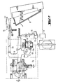
- FIG. 1 or FIG. 2 a combined, only partially shown, at least partially rotating and / or striking electric hand tool one rotatable mode selector switch 1 on.
- the mode selector switch 1 is between one Lubricated assembly 2a with a clutch 3a and an outer housing 4th arranged shift linkage 5 displaceable.
- each of the two separate lubricant tightness Assemblies 2a, 2b in the form of a grease-lubricated gear assembly and one Oil-lubricated hammer mechanism assembly is a switchable clutch 3a, 3b available, each of which is located outside of a module housing 7 extending actuating means 6a, 6b which are mounted in a lubricant-tight manner with O-rings 12a, 12b are rotatably displaceable in the module housing 7.
- the actuating means 6a, 6b are with eccentrically arranged eccentric pin 8a, 8b, each in an opening of the Engage shift linkage 5 feasible, as well as engaging in the shift clutches 3a, 3b Control projections 13a, 13b formed.
- the mode selector switch 1 Via the special functions of the mode selector switch 1 is mediated via the shift linkage 5 and a locking lever arrangement 15 mechanically Motor switch 9 lockable when switched on and electronically via a non-contact, in the form of a Hall switch controlled by a magnetic rocker 16 trained sensor switch 10 and engine electronics 11, the engine speed variable.
Landscapes
- Engineering & Computer Science (AREA)
- Mechanical Engineering (AREA)
- Percussive Tools And Related Accessories (AREA)
- Drilling And Boring (AREA)
- Portable Power Tools In General (AREA)
Abstract
Description
- Fig. 1
- als kombinierte Elektrohandwerkzeugmaschine
- Fig. 2
- als Modiwahlschalter mit Sonderfunktionen
Claims (5)
- Kombinierte Elektrohandwerkzeugmaschine mit einem Modiwahlschalter (1) mit weiteren, über ein zwischen einer geschmierten Baugruppe (2a) mit einer Schaltkupplung (3a) und dem Aussengehäuse (4) angeordnetes sowie vom Modiwahlschalter (1) versetzbares Schaltgestänge (5), schaltbaren Sonderfunktionen, dadurch gekennzeichnet, dass in zumindest zwei getrennt schmiermitteldichten Baugruppen (2a, 2b) jeweils zumindest eine schaltbare Schaltkupplung (3a, 3b) vorhanden ist, welche jeweils über ein sich nach ausserhalb erstreckendes, schmiermitteldicht gelagertes Betätigungsmittel (6a, 6b) versetzbar sind.
- Elektrohandwerkzeugmaschine nach Anspruch 1, dadurch gekennzeichnet, dass das Betätigungsmittel (6a, 6b) als in einem Baugruppengehäuse (7) drehversetzbares, schmiermitteldicht gelagertes Drehbetätigungsmittel ausgebildet ist.
- Elektrohandwerkzeugmaschine nach Anspruch 2, dadurch gekennzeichnet, dass das Drehbetätigungsmittel einen exzentrisch angeordneten Exzenterzapfen (8a, 8b) aufweist, welcher in eine, optional längliche, Öffnung des Schaltgestänges (5) führbar eingreift.
- Elektrohandwerkzeugmaschine nach Anspruch 1, dadurch gekennzeichnet, dass eine erste schmiermitteldichte Baugruppe (2a) als fettgeschmierte Getriebebaugruppe und eine zweite schmiermitteldichte Baugruppe (2b) als ölgeschmierte Schlagwerksbaugruppe ausgebildet ist.
- Elektrohandwerkzeugmaschine nach einem der vorherigen Ansprüche, dadurch gekennzeichnet, dass über eine Sonderfunktion des Modiwahlschalters (1) vermittelt mit dem Schaltgestänge (5) ein Motorschalter (9) arretierbar und/oder elektronisch über einen Sensorschalter (10) und eine Motorelektronik (11) die Motordrehzahl veränderbar ist.
Applications Claiming Priority (2)
| Application Number | Priority Date | Filing Date | Title |
|---|---|---|---|
| DE10225239 | 2002-06-06 | ||
| DE10225239A DE10225239A1 (de) | 2002-06-06 | 2002-06-06 | Modiwahlschalter für kombinierte Elektrohandwerkzeugmaschine |
Publications (2)
| Publication Number | Publication Date |
|---|---|
| EP1369207A1 true EP1369207A1 (de) | 2003-12-10 |
| EP1369207B1 EP1369207B1 (de) | 2009-07-29 |
Family
ID=29432686
Family Applications (1)
| Application Number | Title | Priority Date | Filing Date |
|---|---|---|---|
| EP03405384A Expired - Lifetime EP1369207B1 (de) | 2002-06-06 | 2003-05-27 | Kombinierte elektrohandwerkzeugmaschine mit einem Modiwahlschalter |
Country Status (5)
| Country | Link |
|---|---|
| US (1) | US6725944B2 (de) |
| EP (1) | EP1369207B1 (de) |
| JP (1) | JP4570337B2 (de) |
| CN (1) | CN1467057A (de) |
| DE (2) | DE10225239A1 (de) |
Cited By (4)
| Publication number | Priority date | Publication date | Assignee | Title |
|---|---|---|---|---|
| US7174969B2 (en) | 2003-05-14 | 2007-02-13 | Black & Decker Inc. | Rotary hammer |
| EP1792692A3 (de) * | 2005-12-02 | 2009-04-01 | Makita Corporation | Kraftwerkzeug |
| EP2030738A3 (de) * | 2007-08-29 | 2012-09-12 | HILTI Aktiengesellschaft | Vibrierende Handwerkzeugmaschine mit einem Arretierschalter des Motorschalters |
| EP3593951A1 (de) * | 2018-07-11 | 2020-01-15 | Hilti Aktiengesellschaft | Handwerkzeugmaschine |
Families Citing this family (28)
| Publication number | Priority date | Publication date | Assignee | Title |
|---|---|---|---|---|
| DE10240361A1 (de) * | 2002-09-02 | 2004-03-11 | Hilti Ag | Drehende und schlagende Elektrohandwerkzeugmaschine |
| DE102004018084B3 (de) * | 2004-04-08 | 2005-11-17 | Hilti Ag | Hammerbohrgerät |
| JP4509662B2 (ja) * | 2004-06-16 | 2010-07-21 | 株式会社マキタ | 電動打撃工具 |
| JP4527468B2 (ja) * | 2004-08-17 | 2010-08-18 | 株式会社マキタ | 電動工具 |
| EP1640118B1 (de) * | 2004-09-22 | 2007-11-14 | BLACK & DECKER INC. | Verriegelbare Drucktaste für einen Bohrhammer |
| GB0428210D0 (en) * | 2004-12-23 | 2005-01-26 | Black & Decker Inc | Mode change mechanism |
| GB0503558D0 (en) * | 2005-02-22 | 2005-03-30 | Black & Decker Inc | Actuation apparatus for power tool |
| GB0503784D0 (en) * | 2005-02-24 | 2005-03-30 | Black & Decker Inc | Hammer drill |
| JP4812471B2 (ja) * | 2006-03-09 | 2011-11-09 | 株式会社マキタ | 作業工具 |
| DE102006000287A1 (de) * | 2006-06-09 | 2007-12-13 | Hilti Ag | Handwerkzeuggerät mit Vibrationsminderungseinrichtung |
| JP4981506B2 (ja) * | 2007-04-12 | 2012-07-25 | 株式会社マキタ | ハンマードリル |
| DE102007000362A1 (de) | 2007-07-02 | 2009-01-08 | Hilti Aktiengesellschaft | Vibrierende Handwerkzeugmaschine mit einem Arretierschalter des Motorschalters |
| US7798245B2 (en) | 2007-11-21 | 2010-09-21 | Black & Decker Inc. | Multi-mode drill with an electronic switching arrangement |
| US7854274B2 (en) | 2007-11-21 | 2010-12-21 | Black & Decker Inc. | Multi-mode drill and transmission sub-assembly including a gear case cover supporting biasing |
| US7762349B2 (en) | 2007-11-21 | 2010-07-27 | Black & Decker Inc. | Multi-speed drill and transmission with low gear only clutch |
| US7735575B2 (en) | 2007-11-21 | 2010-06-15 | Black & Decker Inc. | Hammer drill with hard hammer support structure |
| US7717192B2 (en) | 2007-11-21 | 2010-05-18 | Black & Decker Inc. | Multi-mode drill with mode collar |
| US7717191B2 (en) | 2007-11-21 | 2010-05-18 | Black & Decker Inc. | Multi-mode hammer drill with shift lock |
| US7770660B2 (en) | 2007-11-21 | 2010-08-10 | Black & Decker Inc. | Mid-handle drill construction and assembly process |
| US7861799B2 (en) * | 2008-03-21 | 2011-01-04 | Makita Corporation | Impact tool |
| JP5405864B2 (ja) * | 2009-03-23 | 2014-02-05 | 株式会社マキタ | 打撃工具 |
| DE102010038750A1 (de) * | 2010-08-02 | 2012-02-02 | Robert Bosch Gmbh | Elektrowerkzeugmaschine mit arretierbarer Schaltwippe |
| US9630307B2 (en) | 2012-08-22 | 2017-04-25 | Milwaukee Electric Tool Corporation | Rotary hammer |
| JP6912224B2 (ja) * | 2017-03-03 | 2021-08-04 | 株式会社マキタ | 作業工具 |
| WO2019094247A1 (en) | 2017-11-07 | 2019-05-16 | Milwaukee Electric Tool Corporation | Non-contact speed selector swtich in rotary power tool |
| JP7601555B2 (ja) * | 2020-02-03 | 2024-12-17 | 株式会社マキタ | ハンマドリル |
| JP2022158636A (ja) * | 2021-04-02 | 2022-10-17 | 株式会社マキタ | 電動工具及びインパクト工具 |
| EP4257293A1 (de) * | 2022-04-08 | 2023-10-11 | Milwaukee Electric Tool Corporation | Bohrhammer |
Citations (7)
| Publication number | Priority date | Publication date | Assignee | Title |
|---|---|---|---|---|
| EP0437716A1 (de) * | 1990-01-13 | 1991-07-24 | Robert Bosch Gmbh | Elektrisch betriebene Handwerkzeugmaschine |
| DE4216808A1 (de) * | 1992-05-21 | 1993-11-25 | Hilti Ag | Bohr- und Meisselgerät |
| EP0775555A1 (de) * | 1995-11-24 | 1997-05-28 | Black & Decker Inc. | Drehbohrhammer |
| US5664634A (en) * | 1995-10-23 | 1997-09-09 | Waxing Corporation Of America, Inc. | Power tool |
| DE19716976A1 (de) * | 1997-04-23 | 1998-10-29 | Bosch Gmbh Robert | Elektrowerkzeugmaschine |
| US6015017A (en) * | 1997-04-18 | 2000-01-18 | Black & Decker Inc. | Rotary hammer |
| US6176321B1 (en) * | 1998-09-16 | 2001-01-23 | Makita Corporation | Power-driven hammer drill having an improved operating mode switch-over mechanism |
Family Cites Families (7)
| Publication number | Priority date | Publication date | Assignee | Title |
|---|---|---|---|---|
| ZA803409B (en) * | 1979-06-18 | 1981-05-27 | Kango Electric Hammers Ltd | Hammer drill |
| DE3807078A1 (de) * | 1988-03-04 | 1989-09-14 | Black & Decker Inc | Bohrhammer |
| JPH0362712U (de) * | 1989-10-20 | 1991-06-19 | ||
| JP2000033507A (ja) * | 1998-07-16 | 2000-02-02 | Ryobi Ltd | ハンマードリルの打撃力調整機構 |
| JP3688943B2 (ja) * | 1999-08-26 | 2005-08-31 | 株式会社マキタ | ハンマードリル |
| DE10033100A1 (de) * | 2000-07-07 | 2002-01-17 | Hilti Ag | Kombiniertes Elektrohandwerkzeuggerät |
| JP4281273B2 (ja) * | 2000-10-20 | 2009-06-17 | 日立工機株式会社 | ハンマドリル |
-
2002
- 2002-06-06 DE DE10225239A patent/DE10225239A1/de not_active Withdrawn
-
2003
- 2003-05-27 EP EP03405384A patent/EP1369207B1/de not_active Expired - Lifetime
- 2003-05-27 DE DE50311744T patent/DE50311744D1/de not_active Expired - Lifetime
- 2003-06-03 US US10/453,348 patent/US6725944B2/en not_active Expired - Lifetime
- 2003-06-03 JP JP2003157849A patent/JP4570337B2/ja not_active Expired - Fee Related
- 2003-06-04 CN CNA031406963A patent/CN1467057A/zh active Pending
Patent Citations (7)
| Publication number | Priority date | Publication date | Assignee | Title |
|---|---|---|---|---|
| EP0437716A1 (de) * | 1990-01-13 | 1991-07-24 | Robert Bosch Gmbh | Elektrisch betriebene Handwerkzeugmaschine |
| DE4216808A1 (de) * | 1992-05-21 | 1993-11-25 | Hilti Ag | Bohr- und Meisselgerät |
| US5664634A (en) * | 1995-10-23 | 1997-09-09 | Waxing Corporation Of America, Inc. | Power tool |
| EP0775555A1 (de) * | 1995-11-24 | 1997-05-28 | Black & Decker Inc. | Drehbohrhammer |
| US6015017A (en) * | 1997-04-18 | 2000-01-18 | Black & Decker Inc. | Rotary hammer |
| DE19716976A1 (de) * | 1997-04-23 | 1998-10-29 | Bosch Gmbh Robert | Elektrowerkzeugmaschine |
| US6176321B1 (en) * | 1998-09-16 | 2001-01-23 | Makita Corporation | Power-driven hammer drill having an improved operating mode switch-over mechanism |
Cited By (6)
| Publication number | Priority date | Publication date | Assignee | Title |
|---|---|---|---|---|
| US7174969B2 (en) | 2003-05-14 | 2007-02-13 | Black & Decker Inc. | Rotary hammer |
| EP1792692A3 (de) * | 2005-12-02 | 2009-04-01 | Makita Corporation | Kraftwerkzeug |
| EP2030738A3 (de) * | 2007-08-29 | 2012-09-12 | HILTI Aktiengesellschaft | Vibrierende Handwerkzeugmaschine mit einem Arretierschalter des Motorschalters |
| EP3593951A1 (de) * | 2018-07-11 | 2020-01-15 | Hilti Aktiengesellschaft | Handwerkzeugmaschine |
| WO2020011595A1 (de) * | 2018-07-11 | 2020-01-16 | Hilti Aktiengesellschaft | Handwerkzeugmaschine |
| US11958175B2 (en) | 2018-07-11 | 2024-04-16 | Hilti Aktiengesellschaft | Hand-held power tool |
Also Published As
| Publication number | Publication date |
|---|---|
| EP1369207B1 (de) | 2009-07-29 |
| JP2004009291A (ja) | 2004-01-15 |
| CN1467057A (zh) | 2004-01-14 |
| JP4570337B2 (ja) | 2010-10-27 |
| US20030226673A1 (en) | 2003-12-11 |
| US6725944B2 (en) | 2004-04-27 |
| DE50311744D1 (de) | 2009-09-10 |
| DE10225239A1 (de) | 2003-12-18 |
Similar Documents
| Publication | Publication Date | Title |
|---|---|---|
| EP1369207B1 (de) | Kombinierte elektrohandwerkzeugmaschine mit einem Modiwahlschalter | |
| DE10157831B4 (de) | Handwerkzeugmaschine mit einem ein Werkzeug aufnehmenden Döpper | |
| EP1940593A1 (de) | Elektrowerkzeugmaschine | |
| DE102005056205A1 (de) | Bohrhammer mit drei Betriebsarten | |
| DE102005041447A1 (de) | Bohrhammer | |
| EP2097225A1 (de) | Handwerkzeugmaschine | |
| CH695369A5 (de) | Schaltwerk für ein kombiniertes Handwerkzeuggerät. | |
| CH698255B1 (de) | Handwerkzeugmaschine zum Bohren, Hammerbohren oder Meisseln. | |
| DE102018112213B4 (de) | Getriebeaktor mit Pumpe | |
| DE10149216A1 (de) | Handwerkzeugmaschine | |
| EP1234640B1 (de) | Modenwahldrehschalter für ein Handwerkzeuggerät | |
| EP0884138A2 (de) | Bohrhammer | |
| EP1259357B1 (de) | Werkzeugmaschine | |
| WO2009083311A1 (de) | Handwerkzeugmaschine | |
| EP2700477B1 (de) | Getriebeanordnung für eine Werkzeugmaschine sowie Werkzeugmaschine | |
| EP1420921B1 (de) | Handwerkzeugmaschine, insbesondere bohr- und/oder meisselhammer | |
| DE102004055236A1 (de) | Handwerkzeugmaschine mit wählbaren Betriebarten | |
| EP2097224A1 (de) | Handwerkzeugmaschine | |
| DE10357962B3 (de) | Bohrhammer | |
| DE102006061600A1 (de) | Elektrohandwerkzeuggerät | |
| CH692777A5 (de) | Elektrowerkzeugmaschine. | |
| DE10249139A1 (de) | Luftpolsterschlagwerk | |
| DE10115119A1 (de) | Handwerkzeuggerät mit Schaltwerk | |
| EP1127644A2 (de) | Elektrohandwerkzeug | |
| DE102004056411A1 (de) | Handwerkzeugmaschine mit Betriebsartumschaltung |
Legal Events
| Date | Code | Title | Description |
|---|---|---|---|
| PUAI | Public reference made under article 153(3) epc to a published international application that has entered the european phase |
Free format text: ORIGINAL CODE: 0009012 |
|
| AK | Designated contracting states |
Kind code of ref document: A1 Designated state(s): AT BE BG CH CY CZ DE DK EE ES FI FR GB GR HU IE IT LI LU MC NL PT RO SE SI SK TR |
|
| AX | Request for extension of the european patent |
Extension state: AL LT LV MK |
|
| 17P | Request for examination filed |
Effective date: 20040611 |
|
| AKX | Designation fees paid |
Designated state(s): CH DE FR GB IT LI SE |
|
| 17Q | First examination report despatched |
Effective date: 20041029 |
|
| 17Q | First examination report despatched |
Effective date: 20041029 |
|
| RTI1 | Title (correction) |
Free format text: ELECTRIC HAND TOOL WITH MODE SELECTION SWITCH |
|
| GRAP | Despatch of communication of intention to grant a patent |
Free format text: ORIGINAL CODE: EPIDOSNIGR1 |
|
| GRAS | Grant fee paid |
Free format text: ORIGINAL CODE: EPIDOSNIGR3 |
|
| GRAA | (expected) grant |
Free format text: ORIGINAL CODE: 0009210 |
|
| AK | Designated contracting states |
Kind code of ref document: B1 Designated state(s): CH DE FR GB IT LI SE |
|
| REG | Reference to a national code |
Ref country code: GB Ref legal event code: FG4D Free format text: NOT ENGLISH |
|
| REG | Reference to a national code |
Ref country code: CH Ref legal event code: EP |
|
| REF | Corresponds to: |
Ref document number: 50311744 Country of ref document: DE Date of ref document: 20090910 Kind code of ref document: P |
|
| REG | Reference to a national code |
Ref country code: SE Ref legal event code: TRGR |
|
| PLBE | No opposition filed within time limit |
Free format text: ORIGINAL CODE: 0009261 |
|
| STAA | Information on the status of an ep patent application or granted ep patent |
Free format text: STATUS: NO OPPOSITION FILED WITHIN TIME LIMIT |
|
| 26N | No opposition filed |
Effective date: 20100503 |
|
| PGFP | Annual fee paid to national office [announced via postgrant information from national office to epo] |
Ref country code: CH Payment date: 20120514 Year of fee payment: 10 |
|
| PGFP | Annual fee paid to national office [announced via postgrant information from national office to epo] |
Ref country code: SE Payment date: 20120511 Year of fee payment: 10 Ref country code: GB Payment date: 20120523 Year of fee payment: 10 Ref country code: FR Payment date: 20120608 Year of fee payment: 10 |
|
| PGFP | Annual fee paid to national office [announced via postgrant information from national office to epo] |
Ref country code: IT Payment date: 20120518 Year of fee payment: 10 |
|
| REG | Reference to a national code |
Ref country code: CH Ref legal event code: PL |
|
| REG | Reference to a national code |
Ref country code: SE Ref legal event code: EUG |
|
| GBPC | Gb: european patent ceased through non-payment of renewal fee |
Effective date: 20130527 |
|
| PG25 | Lapsed in a contracting state [announced via postgrant information from national office to epo] |
Ref country code: SE Free format text: LAPSE BECAUSE OF NON-PAYMENT OF DUE FEES Effective date: 20130528 Ref country code: LI Free format text: LAPSE BECAUSE OF NON-PAYMENT OF DUE FEES Effective date: 20130531 Ref country code: CH Free format text: LAPSE BECAUSE OF NON-PAYMENT OF DUE FEES Effective date: 20130531 |
|
| PG25 | Lapsed in a contracting state [announced via postgrant information from national office to epo] |
Ref country code: IT Free format text: LAPSE BECAUSE OF NON-PAYMENT OF DUE FEES Effective date: 20130527 |
|
| REG | Reference to a national code |
Ref country code: FR Ref legal event code: ST Effective date: 20140131 |
|
| PG25 | Lapsed in a contracting state [announced via postgrant information from national office to epo] |
Ref country code: GB Free format text: LAPSE BECAUSE OF NON-PAYMENT OF DUE FEES Effective date: 20130527 |
|
| PG25 | Lapsed in a contracting state [announced via postgrant information from national office to epo] |
Ref country code: FR Free format text: LAPSE BECAUSE OF NON-PAYMENT OF DUE FEES Effective date: 20130531 |
|
| PGFP | Annual fee paid to national office [announced via postgrant information from national office to epo] |
Ref country code: DE Payment date: 20220519 Year of fee payment: 20 |
|
| REG | Reference to a national code |
Ref country code: DE Ref legal event code: R071 Ref document number: 50311744 Country of ref document: DE |