EP1369200B1 - Device for polishing optical disk - Google Patents
Device for polishing optical disk Download PDFInfo
- Publication number
- EP1369200B1 EP1369200B1 EP02701709A EP02701709A EP1369200B1 EP 1369200 B1 EP1369200 B1 EP 1369200B1 EP 02701709 A EP02701709 A EP 02701709A EP 02701709 A EP02701709 A EP 02701709A EP 1369200 B1 EP1369200 B1 EP 1369200B1
- Authority
- EP
- European Patent Office
- Prior art keywords
- polishing
- optical disk
- disk
- sheet
- elastic
- Prior art date
- Legal status (The legal status is an assumption and is not a legal conclusion. Google has not performed a legal analysis and makes no representation as to the accuracy of the status listed.)
- Expired - Lifetime
Links
- 238000005498 polishing Methods 0.000 title claims abstract description 171
- 230000003287 optical effect Effects 0.000 title claims abstract description 59
- 230000037431 insertion Effects 0.000 claims 1
- 238000003780 insertion Methods 0.000 claims 1
- 238000007599 discharging Methods 0.000 abstract 1
- 230000002093 peripheral effect Effects 0.000 abstract 1
- 238000010008 shearing Methods 0.000 abstract 1
- 230000008030 elimination Effects 0.000 description 7
- 238000003379 elimination reaction Methods 0.000 description 7
- 229920003051 synthetic elastomer Polymers 0.000 description 6
- 239000005061 synthetic rubber Substances 0.000 description 6
- 239000006061 abrasive grain Substances 0.000 description 5
- 239000000758 substrate Substances 0.000 description 5
- 230000007423 decrease Effects 0.000 description 4
- 238000009991 scouring Methods 0.000 description 4
- 239000002184 metal Substances 0.000 description 3
- 230000000694 effects Effects 0.000 description 2
- 239000004744 fabric Substances 0.000 description 2
- 239000000463 material Substances 0.000 description 2
- 229920000515 polycarbonate Polymers 0.000 description 2
- 239000004417 polycarbonate Substances 0.000 description 2
- 239000000843 powder Substances 0.000 description 2
- 230000001105 regulatory effect Effects 0.000 description 2
- 239000007788 liquid Substances 0.000 description 1
- 238000005259 measurement Methods 0.000 description 1
- XLYOFNOQVPJJNP-UHFFFAOYSA-N water Substances O XLYOFNOQVPJJNP-UHFFFAOYSA-N 0.000 description 1
Images



Classifications
-
- G—PHYSICS
- G11—INFORMATION STORAGE
- G11B—INFORMATION STORAGE BASED ON RELATIVE MOVEMENT BETWEEN RECORD CARRIER AND TRANSDUCER
- G11B23/00—Record carriers not specific to the method of recording or reproducing; Accessories, e.g. containers, specially adapted for co-operation with the recording or reproducing apparatus ; Intermediate mediums; Apparatus or processes specially adapted for their manufacture
- G11B23/50—Reconditioning of record carriers; Cleaning of record carriers ; Carrying-off electrostatic charges
- G11B23/505—Reconditioning of record carriers; Cleaning of record carriers ; Carrying-off electrostatic charges of disk carriers
-
- B—PERFORMING OPERATIONS; TRANSPORTING
- B24—GRINDING; POLISHING
- B24B—MACHINES, DEVICES, OR PROCESSES FOR GRINDING OR POLISHING; DRESSING OR CONDITIONING OF ABRADING SURFACES; FEEDING OF GRINDING, POLISHING, OR LAPPING AGENTS
- B24B7/00—Machines or devices designed for grinding plane surfaces on work, including polishing plane glass surfaces; Accessories therefor
- B24B7/20—Machines or devices designed for grinding plane surfaces on work, including polishing plane glass surfaces; Accessories therefor characterised by a special design with respect to properties of the material of non-metallic articles to be ground
- B24B7/22—Machines or devices designed for grinding plane surfaces on work, including polishing plane glass surfaces; Accessories therefor characterised by a special design with respect to properties of the material of non-metallic articles to be ground for grinding inorganic material, e.g. stone, ceramics, porcelain
- B24B7/228—Machines or devices designed for grinding plane surfaces on work, including polishing plane glass surfaces; Accessories therefor characterised by a special design with respect to properties of the material of non-metallic articles to be ground for grinding inorganic material, e.g. stone, ceramics, porcelain for grinding thin, brittle parts, e.g. semiconductors, wafers
-
- B—PERFORMING OPERATIONS; TRANSPORTING
- B24—GRINDING; POLISHING
- B24D—TOOLS FOR GRINDING, BUFFING OR SHARPENING
- B24D13/00—Wheels having flexibly-acting working parts, e.g. buffing wheels; Mountings therefor
- B24D13/14—Wheels having flexibly-acting working parts, e.g. buffing wheels; Mountings therefor acting by the front face
-
- B—PERFORMING OPERATIONS; TRANSPORTING
- B24—GRINDING; POLISHING
- B24D—TOOLS FOR GRINDING, BUFFING OR SHARPENING
- B24D13/00—Wheels having flexibly-acting working parts, e.g. buffing wheels; Mountings therefor
- B24D13/20—Mountings for the wheels
Definitions
- the present invention relates to a polishing apparatus for restoring optical disks, such as CD, DVD, VD and LD.
- US 5,938,510 which is regarded to represent the closest state of the art according to the preamble of claim 1, discloses a disc cleaner/scourer/polisher device comprising two holders, one holder holding a scouring member for scratch removal and one holder holding a scouring member for polishing, both scouring the annular portion of the planar side of the supported disc.
- Each holder has a respective pressing/lifting mechanism for moving the respective holder relative to the planar side of the supported disc for effecting/breaking the contact of the respective scouring member with an annular portion of the planar side of the supported disc, independent of at least one other of the holders.
- US 5,860,851 discloses a polishing apparatus comprising an elastic member interposed between a polishing table and a polishing cloth, with that polishing cloth being moveable independent of the elastic member.
- US 4,825,497 discloses a disk cleaner comprising a driving mechanism which is operated when a lid is positioned in a closed condition relative to a main casing.
- the driving mechanism is operatively connected to another mechanism for rotating and revolving a cleaner body to clean the disk.
- optical disks have been selling in large quantities. When a flaw or flaws are made on its surface, it is sometimes impossible to read data from the disk. It is therefore desirable to repair the disk and restore it to a readable state. In view of resource saving, it is not desirable to dispose of such reusable optical disks in large quantities.
- Fig. 5 shows an example of a conventional disk polishing apparatus.
- the apparatus is composed of a disk rotator A2 for rotating an object 31 and a polishing mechanism B2 for polishing the surface of the object 31.
- a polishing pad C2 is attached to a rotating substrate 33 fixed to a rotation shaft 32 via such an attachment means as "Velcro" (registered trademark).
- a polishing sheet 36 is attached to the bottom of a spongy elastic body 35.
- Fig. 6a shows the case of polishing the surface of an optical disk with the above-constructed polishing apparatus.
- the elastic body 35 of the polishing pad C2 is too soft, deformation occurs in the polishing face.
- roundness E is formed on the outer edge of the optical disk 31.
- the elastic body 35 of the polishing pad C2 When, on the other hand, the elastic body 35 of the polishing pad C2 is not pliable, the pressure contact between the polishing face and the surface of the optical disk is tightened in part. It is therefore difficult to eliminate abrasive filings (e.g. polycarbonate powder), which clog the surface of the polishing sheet. Thus, the polishing power decreases and the accumulated filings cause small shallow cuts (i.e. scratches) on the surface of the optical disk.
- abrasive filings e.g. polycarbonate powder
- the problems to be solved by the present invention are as follows: (1) to obtain an appropriate pressure required for polishing; (2) to correct the accuracy of parallelism between the rotation planes of an optical disk and a polishing sheet; (3) to remove roundness formed on the outer edge of an optical disk and unevenness in polishing; and (4) to prevent clogging of the surface of a polishing sheet by the active elimination of abrasive filings and an occurrence of scratches on the surface of an optical disk due to the clogging.
- the polishing mechanism B has an elastic mechanism D for elastically holding a polishing pad C and the elastic mechanism D is constructed to have elasticity in the direction perpendicular to the rotation plane of the optical disk and rigidity in the direction parallel to the rotation plane of the optical disk.
- an apparatus for polishing an optical disk composed of a disk rotator A for rotating an optical disk and a polishing mechanism B for polishing the surface of the optical disk wherein the ratio of the disk angular speed omega a of the disk rotator A to the polishing sheet angular speed omega b of the polishing mechanism B satisfies the range of 0.2 ⁇ ⁇ a/ ⁇ b ⁇ 1.5.
- a wet polishing apparatus is used in the present embodiment.
- the wet polishing apparatus when the surface 2a of a polishing sheet of a polishing pad C is pressed into contact with the surface 1a of an optical disk for the purpose of polishing, such liquid as water is supplied to the interface between the surfaces 1a and 2a. Thereby, frictional heat is eased and the elimination of filings is attained in the course of polishing.
- Figs. 1 and 2 show an apparatus for polishing an optical disk according to the present embodiment.
- the apparatus is composed of a disk rotator A for rotating an optical disk 1 and a polishing mechanism B for polishing the surface of the optical disk.
- the polishing mechanism B has an elastic mechanism D for elastically holding a polishing pad C.
- the optical disk 1 is mounted on a rotating substrate 4 coupled with a rotation shaft 3.
- the elastic mechanism D is constructed so that a second rigid body 7 is connected to a first rigid body 6 in a floating state, as shown in Figs. 2 and 3.
- the polishing pad C is attached to the second rigid body 7.
- plural shafts 7a project upward from its circumferential vicinity.
- the first rigid body 6 is coupled with a rotation shaft 5.
- plural shaft holes 6a are provided in its circumferential vicinity.
- the shaft 7a is fitted into the shaft hole 6a through a coil spring 8 between rigid bodies 6 and 7.
- the shaft 7a is capable of sliding and is fixed by a fixing member 9.
- the elastic mechanism D is therefore constructed to have elasticity in the direction perpendicular to the rotation plane of the optical disk 1 and rigidity in the direction parallel to the rotation plane of the optical disk 1.
- a magnetic body 10 is provided on the bottom of the second rigid body 7. The magnetic body 10 is magnetically joined with a metal substrate 11 of the polishing pad C as described later.
- a polishing sheet 2 is attached via an elastic sheet 12 to the metal substrate 11 joined with the magnetic body 10.
- the polishing pad C can be attached to the second rigid body 7 by a Hook-and-Loop fastener, such as "Velcro” (registered trademark), in addition to the magnetic attachment/detachment means.
- a Hook-and-Loop fastener such as "Velcro” (registered trademark)
- the integrated elastic mechanism D and polishing pad C may be attached to and detached from the rotation shaft 5.
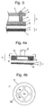
- Figs. 4a and 4b show another type of the elastic mechanism D.
- a magnetic body 20 is attached via a ring 29 to a ribbed elastic body 28 fixed to a rotation shaft 25 of a polishing mechanism B1.
- Fig. 4b which is a plan view of the elastic mechanism shown in Fig. 4a
- the ribbed elastic body 28 is formed so that an inner part 28a is connected to an outer part 28b by ribs 28d while creating a space 28c.
- the elastic mechanism D1 is thus constructed. Therefore, the elastic mechanism D 1 is also constructed to have elasticity in the direction perpendicular to the rotation plane of the optical disk and rigidity in the direction parallel to the rotation plane of the optical disk.
- the polishing pads were prepared by using the elastic sheets that differed in material and thickness. Next, these polishing pads were attached to the polishing mechanism B of the polishing apparatus according to the present embodiment. The surface of the polishing sheet of each polishing pad was pressed into contact with the surface of the optical disk with a pressure required for polishing. Samples 1-6 were thus obtained. Reference is made to Table 1, which shows the deformation amount ⁇ x of the surface of the polishing sheet in this case. Table 1 also shows the comprehensive as well as the individual rating regarding clogging of the surface of the polishing sheet and roundness formed on the outer edge of the optical disk. In the present experiment, the rotation speed of the disk rotator A is 500 rpm and that of the polishing mechanism B is 1200 rpm. The disk rotator A and the polishing mechanism B rotate in the same direction.
- the deformation amount (depression amount) ⁇ x when the deformation amount (depression amount) ⁇ x is small, the surface of the polishing sheet is likely to be clogged; when it is large, roundness is likely to be formed on the outer edge of the optical disk; and it is preferable to set the deformation amount (depression amount) ⁇ x within the range of 0.005 mm to 0.3 mm, more preferably within the range of 0.01 mm to 0.1 mm.
- the disk angular speed ⁇ a of the disk rotator A and the polishing sheet angular speed ⁇ b of the polishing mechanism B were regulated to set the angular speed ratio at the values shown in Table 2.
- Samples 1-7 were thus obtained. As for these samples, an amount of polishing was measured. In the meantime, the elimination of filings, an occurrence of clogging, etc. were rated. These measurement and ratings are comprehensively shown in the column of "Rating of Amount of Polishing" of Table 2.
- TABLE 2 Sample No. Disk Angular Speed / Polishing Sheet Angular Speed ( ⁇ a/ ⁇ b) Rating of Amount of Polishing 1 0.1 ⁇ 2 0.2 ⁇ 3 0.4 ⁇ 4 0.6 ⁇ 5 1.0 ⁇ 6 1.5 ⁇ 7 2.0 ⁇
- the polishing sheet always effects polishing in the direction La parallel to a trace of polishing Ka, as shown in Fig. 7a.
- the same abrasive grains of the polishing sheet always polish a peak part Y of the traces of polishing Ka
- the other ones always polish a valley part T thereof. Therefore, the polishing efficiency is low and the amount of polishing decreases. Further, the polishing sheet is likely to be clogged because it is difficult to eliminate the filings. Thereby, endurance of the polishing sheet decreases.
- the polishing sheet effects polishing in the direction Lc nearly perpendicular to a trace of polishing Kc, as shown in Fig. 7c. Therefore, differently from the case of the sample No. 1, the same part of the abrasive grains does not polish the peak part Y. That is, the peak part Y and valley part T are polished alternatively. In this case, the filings produced by polishing the peak part T are actively eliminated through the valley part T and thereby an occurrence of clogging is prevented.
Landscapes
- Engineering & Computer Science (AREA)
- Mechanical Engineering (AREA)
- Chemical & Material Sciences (AREA)
- Ceramic Engineering (AREA)
- Inorganic Chemistry (AREA)
- Finish Polishing, Edge Sharpening, And Grinding By Specific Grinding Devices (AREA)
- Manufacturing Optical Record Carriers (AREA)
- Optical Head (AREA)
Abstract
Description
- The present invention relates to a polishing apparatus for restoring optical disks, such as CD, DVD, VD and LD.
-
US 5,938,510 , which is regarded to represent the closest state of the art according to the preamble of claim 1, discloses a disc cleaner/scourer/polisher device comprising two holders, one holder holding a scouring member for scratch removal and one holder holding a scouring member for polishing, both scouring the annular portion of the planar side of the supported disc. Each holder has a respective pressing/lifting mechanism for moving the respective holder relative to the planar side of the supported disc for effecting/breaking the contact of the respective scouring member with an annular portion of the planar side of the supported disc, independent of at least one other of the holders. -
US 5,860,851 discloses a polishing apparatus comprising an elastic member interposed between a polishing table and a polishing cloth, with that polishing cloth being moveable independent of the elastic member. -
US 4,825,497 discloses a disk cleaner comprising a driving mechanism which is operated when a lid is positioned in a closed condition relative to a main casing. The driving mechanism is operatively connected to another mechanism for rotating and revolving a cleaner body to clean the disk. - Recently, optical disks have been selling in large quantities. When a flaw or flaws are made on its surface, it is sometimes impossible to read data from the disk. It is therefore desirable to repair the disk and restore it to a readable state. In view of resource saving, it is not desirable to dispose of such reusable optical disks in large quantities.
- Reference is made to Fig. 5, which shows an example of a conventional disk polishing apparatus. The apparatus is composed of a disk rotator A2 for rotating an
object 31 and a polishing mechanism B2 for polishing the surface of theobject 31. In the polishing mechanism B2, a polishing pad C2 is attached to a rotatingsubstrate 33 fixed to arotation shaft 32 via such an attachment means as "Velcro" (registered trademark). In the polishing pad C2, apolishing sheet 36 is attached to the bottom of a spongyelastic body 35. - Reference is made to Fig. 6a, which shows the case of polishing the surface of an optical disk with the above-constructed polishing apparatus. When the
elastic body 35 of the polishing pad C2 is too soft, deformation occurs in the polishing face. Thus, in the course of polishing, roundness E is formed on the outer edge of theoptical disk 31. - When, on the other hand, the
elastic body 35 of the polishing pad C2 is not pliable, the pressure contact between the polishing face and the surface of the optical disk is tightened in part. It is therefore difficult to eliminate abrasive filings (e.g. polycarbonate powder), which clog the surface of the polishing sheet. Thus, the polishing power decreases and the accumulated filings cause small shallow cuts (i.e. scratches) on the surface of the optical disk. - Further, when the rotation plane of the optical disk is not kept parallel to that of the
polishing sheet 36, it is impossible to adequately correct the planar accuracy of the polished face in the course of polishing, as shown in Fig. 6b. - Accordingly, the problems to be solved by the present invention are as follows: (1) to obtain an appropriate pressure required for polishing; (2) to correct the accuracy of parallelism between the rotation planes of an optical disk and a polishing sheet; (3) to remove roundness formed on the outer edge of an optical disk and unevenness in polishing; and (4) to prevent clogging of the surface of a polishing sheet by the active elimination of abrasive filings and an occurrence of scratches on the surface of an optical disk due to the clogging.
- It is an objective of the present invention to provide an apparatus for polishing an optical disk composed of a disk rotator A for rotating an optical disk and a polishing mechanism B for polishing the surface of the optical disk, wherein the polishing mechanism B has an elastic mechanism D for elastically holding a polishing pad C and a polishing sheet of the polishing pad C has such an elasticity that the deformation amount Δx is 0.005 mm to 0.3 mm when the polishing sheet contacts the surface of the optical disk with a pressure required for polishing.
- In this invention, it is possible to prevent clogging of the surface of the polishing sheet by the active elimination of abrasive filings and an occurrence of scratches on the surface of the optical disk due to the clogging. It is also possible to remove roundness formed on the outer edge of the optical disk and unevenness in polishing by regulating elasticity of the polishing sheet.
- In accordance with the invention, the polishing mechanism B has an elastic mechanism D for elastically holding a polishing pad C and the elastic mechanism D is constructed to have elasticity in the direction perpendicular to the rotation plane of the optical disk and rigidity in the direction parallel to the rotation plane of the optical disk.
- In this invention, it is possible to correct the accuracy of parallelism between the rotation planes of the optical disk and the polishing sheet. Thereby, the pressure contact between the polishing face and the surface of the optical disk can be appropriately equalised. Thus, it is possible to remove roundness formed on the outer edge of the optical disk and unevenness in polishing.
- In an embodiment of the invention, an apparatus for polishing an optical disk composed of a disk rotator A for rotating an optical disk and a polishing mechanism B for polishing the surface of the optical disk is provided, wherein the ratio of the disk angular speed omega a of the disk rotator A to the polishing sheet angular speed omega b of the polishing mechanism B satisfies the range of 0.2<
ω a/ω b<1.5. - Such, it is possible to increase the polishing efficiency and thus obtain an adequate amount of polishing by setting the ratio of the disk angular speed of the disk rotator A and the polishing sheet angular speed of the polishing mechanism B within a predetermined range. It is also possible to prevent an occurrence of clogging by facilitating the elimination of filings. Further, endurance of the polishing sheet can be improved.
-
- Fig. 1 is a perspective view showing the configuration of the disk rotator and the polishing mechanism.
- Fig. 2 is a side view of the polishing mechanism with a polishing pad attached.
- Fig. 3 is a partial sectional view of the polishing mechanism with a polishing pad unattached.
- Fig. 4a is a partial sectional view of another type of elastic mechanism.
- Fig. 4b is a plan view of the elastic mechanism shown in Fig. 4a.
- Fig. 5 is a side view showing the configuration of the conventional disk rotator and polishing mechanism.
- Fig. 6a is a partial sectional view explaining the function of the conventional polishing mechanism.
- Fig. 6b is a partial sectional view explaining the function of the conventional polishing mechanism.
- Fig. 7a is a plan view of a disk of a sample 1 in experiment example 2 and a perspective view of traces of polishing.
- Fig. 7b is a plan view of a disk of a
sample 7 in experiment example 2. - Fig. 7c is a plan view of a disk of a sample 4 in experiment example 2 and a perspective view of traces of polishing.
- An embodiment of the present invention is described according to the drawings. A wet polishing apparatus is used in the present embodiment. In the wet polishing apparatus, when the
surface 2a of a polishing sheet of a polishing pad C is pressed into contact with the surface 1a of an optical disk for the purpose of polishing, such liquid as water is supplied to the interface between thesurfaces 1a and 2a. Thereby, frictional heat is eased and the elimination of filings is attained in the course of polishing. - Reference is made to Figs. 1 and 2, which show an apparatus for polishing an optical disk according to the present embodiment. The apparatus is composed of a disk rotator A for rotating an optical disk 1 and a polishing mechanism B for polishing the surface of the optical disk. The polishing mechanism B has an elastic mechanism D for elastically holding a polishing pad C.
- In the disk rotator A, the optical disk 1 is mounted on a rotating substrate 4 coupled with a
rotation shaft 3. - In the polishing mechanism B, the elastic mechanism D is constructed so that a second
rigid body 7 is connected to a first rigid body 6 in a floating state, as shown in Figs. 2 and 3. The polishing pad C is attached to the secondrigid body 7. In the secondrigid body 7,plural shafts 7a project upward from its circumferential vicinity. The first rigid body 6 is coupled with arotation shaft 5. In the first rigid body 6,plural shaft holes 6a are provided in its circumferential vicinity. Theshaft 7a is fitted into theshaft hole 6a through acoil spring 8 betweenrigid bodies 6 and 7. Theshaft 7a is capable of sliding and is fixed by a fixing member 9. - The elastic mechanism D is therefore constructed to have elasticity in the direction perpendicular to the rotation plane of the optical disk 1 and rigidity in the direction parallel to the rotation plane of the optical disk 1. A
magnetic body 10 is provided on the bottom of the secondrigid body 7. Themagnetic body 10 is magnetically joined with ametal substrate 11 of the polishing pad C as described later. - In the polishing pad C, as shown in Fig. 3, a polishing
sheet 2 is attached via anelastic sheet 12 to themetal substrate 11 joined with themagnetic body 10. - The polishing pad C can be attached to the second
rigid body 7 by a Hook-and-Loop fastener, such as "Velcro" (registered trademark), in addition to the magnetic attachment/detachment means. Instead of the polishing pad C being attached to and detached from the secondrigid body 7, the integrated elastic mechanism D and polishing pad C may be attached to and detached from therotation shaft 5. - Reference is made to Figs. 4a and 4b, which show another type of the elastic mechanism D. In this type elastic mechanism D, a
magnetic body 20 is attached via aring 29 to a ribbedelastic body 28 fixed to arotation shaft 25 of a polishing mechanism B1. As shown in Fig. 4b (which is a plan view of the elastic mechanism shown in Fig. 4a), the ribbedelastic body 28 is formed so that aninner part 28a is connected to anouter part 28b byribs 28d while creating aspace 28c. The elastic mechanism D1 is thus constructed. Therefore, the elastic mechanism D 1 is also constructed to have elasticity in the direction perpendicular to the rotation plane of the optical disk and rigidity in the direction parallel to the rotation plane of the optical disk. - The polishing pads were prepared by using the elastic sheets that differed in material and thickness. Next, these polishing pads were attached to the polishing mechanism B of the polishing apparatus according to the present embodiment. The surface of the polishing sheet of each polishing pad was pressed into contact with the surface of the optical disk with a pressure required for polishing. Samples 1-6 were thus obtained. Reference is made to Table 1, which shows the deformation amount Δx of the surface of the polishing sheet in this case. Table 1 also shows the comprehensive as well as the individual rating regarding clogging of the surface of the polishing sheet and roundness formed on the outer edge of the optical disk. In the present experiment, the rotation speed of the disk rotator A is 500 rpm and that of the polishing mechanism B is 1200 rpm. The disk rotator A and the polishing mechanism B rotate in the same direction.
- In the sample 1, the polishing sheet is directly attached to the
metal substrate 11 of the polishing pad. That is, the elastic sheet is not in use. In the samples 2-6, various kinds of synthetic rubber are used as the elastic sheet. Also, the elastic sheets differ in thickness.TABLE 1 Sample No. Material of Polishing Sheet Deformation Amount Δx (mm) Rating of Clogging Rating of Roundness Comprehensive Rating 1 --- 0.000 × ○ × 2 Synthetic Rubber 0.005 Δ ○ Δ 3 Synthetic Rubber 0.01 ○ ○ ○ 4 Synthetic Rubber 0.1 ○ ○ ○ 5 Synthetic Rubber 0.3 ○ Δ Δ 6 Synthetic Rubber 0.5 ○ × × - Based on this result, the following facts were found: when the deformation amount (depression amount) Δx is small, the surface of the polishing sheet is likely to be clogged; when it is large, roundness is likely to be formed on the outer edge of the optical disk; and it is preferable to set the deformation amount (depression amount) Δx within the range of 0.005 mm to 0.3 mm, more preferably within the range of 0.01 mm to 0.1 mm.
- With the polishing apparatus according to the present embodiment, the disk angular speed ωa of the disk rotator A and the polishing sheet angular speed ωb of the polishing mechanism B were regulated to set the angular speed ratio at the values shown in Table 2. Samples 1-7 were thus obtained. As for these samples, an amount of polishing was measured. In the meantime, the elimination of filings, an occurrence of clogging, etc. were rated. These measurement and ratings are comprehensively shown in the column of "Rating of Amount of Polishing" of Table 2.
TABLE 2 Sample No. Disk Angular Speed / Polishing Sheet Angular Speed (ωa/ωb) Rating of Amount of Polishing 1 0.1 × 2 0.2 Δ 3 0.4 ○ 4 0.6 ⊚ 5 1.0 ○ 6 1.5 Δ 7 2.0 × - As for the sample No. 1 (ratio of 0.1) where the disk angular speed is low and the polishing sheet angular speed is high, the polishing sheet always effects polishing in the direction La parallel to a trace of polishing Ka, as shown in Fig. 7a. In this case, while the same abrasive grains of the polishing sheet always polish a peak part Y of the traces of polishing Ka, the other ones always polish a valley part T thereof. Therefore, the polishing efficiency is low and the amount of polishing decreases. Further, the polishing sheet is likely to be clogged because it is difficult to eliminate the filings. Thereby, endurance of the polishing sheet decreases.
- As for the sample No. 7 (ratio of 2.0) where the disk angular speed is high and the polishing sheet angular speed is low, long-distance polishing is effected while an abrasive grain on the surface of the polishing sheet rotates once, as shown in Fig. 7b. The abrasive grain is therefore likely to have polishing heat. Consequently, when the softened filings stick to the surface of the abrasive grain (i.e. polycarbonate powder), frictional resistance increases due to the clogging and thereby the polishing efficiency decreases.
- As for the sample No. 4 where the ratio of the disk angular speed and the polishing sheet angular speed is 0.6, the polishing sheet effects polishing in the direction Lc nearly perpendicular to a trace of polishing Kc, as shown in Fig. 7c. Therefore, differently from the case of the sample No. 1, the same part of the abrasive grains does not polish the peak part Y. That is, the peak part Y and valley part T are polished alternatively. In this case, the filings produced by polishing the peak part T are actively eliminated through the valley part T and thereby an occurrence of clogging is prevented.
- Based on the above result, the following facts were found: while it is desired to set the ratio of the disk angular speed and the polishing sheet angular speed appropriately, it is preferable to set the angular speed ratio within the range of 0.2<ωa/ωb<1.5, more preferably within the range of 0.4<ωa/ωb<1.0.
- As described above, in this invention, it is possible to prevent clogging of the surface of the polishing sheet by the active elimination of abrasive filings and an occurrence of scratches on the surface of the optical disk due to the clogging. It is also possible to correct the accuracy of parallelism between the rotation planes of the optical disk and the polishing sheet. Thereby, the pressure contact between the polishing face and the surface of the optical disk can be appropriately equalized. Thus, it is possible to remove roundness formed on the outer edge of the optical disk and unevenness in polishing. It is further possible to increase polishing efficiency and thus obtain an adequate amount of polishing by setting the ratio of the disk angular speed of the disk rotator A and the polishing sheet angular speed of the polishing mechanism B within a predetermined range. Furthermore, it is possible to prevent an occurrence of clogging by facilitating the elimination of filings and thereby endurance of the polishing sheet can be improved.
Claims (6)
- An apparatus for polishing an optical disk composed of a disk rotator (A) for rotating an optical disk (1) and a single polishing mechanism (B) for polishing the surface of the optical disk, wherein:the polishing mechanism (B) has an elastic mechanism (D) for elastically holding a polishing pad (C);a polishing sheet of the polishing pad (C) ;the elastic mechanism (D) is constructed to have elasticity in the direction perpendicular to the rotation plane of the optical disk (1) and rigidity in the direction parallel to the rotation plane of the optical disk (1), characterised in thatthe elastic mechanism (D) has elastic members (8) in its circumferential vicinity and the polishing sheet of the polishing pad (C) has such an elasticity that the deformation amount Δx is 0.005 mm to 0.3 mm when the polishing sheet contacts the surface of the optical disk (1) with a pressure required for polishing.
- The apparatus according to claim 1 for polishing an optical disk (1), wherein the ratio of the disk angular speed
ω a of the disk rotator (A) to the polishing sheet angular speedω b of the polishing mechanism (B) satisfies the range of 0.2<ω a/ω b<1.5. - The apparatus for polishing an optical disk (1) according to claim 1 or 2, wherein the elastic mechanism (D) includes:a) a first plate member (7);b) a second plate member (6) sliding against a bar member (7d) provided on the first plate member (7); andc) an elastic member (8) with the bar member (7a) fitted by insertion between the first (7) and second (6) plate members.
- The apparatus for polishing an optical disk (1) according to claim 1 or 2, wherein the elastic mechanism (D) is a ribbed elastic body.
- The apparatus for polishing an optical disk (1) according to one of claims 1 to 4, wherein the polishing pad (C) is attached to and detached from the elastic mechanism (D) by a magnetic attachment/detachment means or a Hook-and-Loop fastener.
- The apparatus for polishing an optical disk (1) according to one of claims 1 to 5, wherein the integrated elastic mechanism (D) and polishing pad (C) are attached to and detached from a rotation shaft (5).
Applications Claiming Priority (3)
| Application Number | Priority Date | Filing Date | Title |
|---|---|---|---|
| JP2001111994 | 2001-03-05 | ||
| JP2001111994 | 2001-03-05 | ||
| PCT/JP2002/001981 WO2002070199A1 (en) | 2001-03-05 | 2002-03-04 | Device for polishing optical disk |
Publications (3)
| Publication Number | Publication Date |
|---|---|
| EP1369200A1 EP1369200A1 (en) | 2003-12-10 |
| EP1369200A4 EP1369200A4 (en) | 2005-11-23 |
| EP1369200B1 true EP1369200B1 (en) | 2007-08-01 |
Family
ID=18963484
Family Applications (1)
| Application Number | Title | Priority Date | Filing Date |
|---|---|---|---|
| EP02701709A Expired - Lifetime EP1369200B1 (en) | 2001-03-05 | 2002-03-04 | Device for polishing optical disk |
Country Status (6)
| Country | Link |
|---|---|
| US (1) | US6869344B2 (en) |
| EP (1) | EP1369200B1 (en) |
| JP (1) | JPWO2002070199A1 (en) |
| DE (1) | DE60221502T2 (en) |
| ES (1) | ES2287242T3 (en) |
| WO (1) | WO2002070199A1 (en) |
Cited By (1)
| Publication number | Priority date | Publication date | Assignee | Title |
|---|---|---|---|---|
| CN109531338A (en) * | 2018-12-29 | 2019-03-29 | 重庆荣成玻璃制品有限公司 | Glass blow pressure process units |
Families Citing this family (30)
| Publication number | Priority date | Publication date | Assignee | Title |
|---|---|---|---|---|
| US7104871B1 (en) * | 1997-06-20 | 2006-09-12 | Kennedy Michael S | Method and apparatus for reconditioning compact discs |
| DE102004001546A1 (en) * | 2004-01-10 | 2005-08-04 | August Rüggeberg Gmbh & Co. Kg | Tool |
| FR2900356B1 (en) * | 2006-04-27 | 2008-07-18 | Essilor Int | TOOL FOR SURFACING AN OPTICAL SURFACE |
| ATE512314T1 (en) * | 2007-04-23 | 2011-06-15 | Htc Sweden Ab | GRINDING HOLDER OF A PROCESSING DEVICE |
| KR100893067B1 (en) * | 2008-02-22 | 2009-04-17 | 이중호 | Flexible Wrapping Machine |
| FR2935628B1 (en) * | 2008-09-10 | 2011-10-14 | Essilor Int | SURFACE TOOL WITH OPTICAL QUALITY |
| US20100087124A1 (en) * | 2008-10-07 | 2010-04-08 | Farzad Saghian | Cd repair apparatus |
| KR101034506B1 (en) * | 2008-11-28 | 2011-05-17 | 세메스 주식회사 | Polishing unit, substrate polishing apparatus having same, and substrate polishing method using same |
| JP5408790B2 (en) * | 2009-03-06 | 2014-02-05 | エルジー・ケム・リミテッド | Float glass polishing system |
| JP5408788B2 (en) * | 2009-03-06 | 2014-02-05 | エルジー・ケム・リミテッド | Float glass polishing system |
| JP5408789B2 (en) * | 2009-03-06 | 2014-02-05 | エルジー・ケム・リミテッド | Float glass polishing system |
| JP5388212B2 (en) * | 2009-03-06 | 2014-01-15 | エルジー・ケム・リミテッド | Lower unit for float glass polishing system |
| US20100330890A1 (en) * | 2009-06-30 | 2010-12-30 | Zine-Eddine Boutaghou | Polishing pad with array of fluidized gimballed abrasive members |
| KR101342952B1 (en) * | 2009-10-08 | 2013-12-18 | 주식회사 엘지화학 | method and system for polishing glass |
| CN101884981B (en) * | 2010-06-10 | 2012-12-26 | 北京中电科电子装备有限公司 | Wafer cleaning device |
| US20130181465A1 (en) * | 2012-01-17 | 2013-07-18 | Elm Inc. | Optical disc restoration method and system |
| DE202012002267U1 (en) * | 2012-03-07 | 2012-04-18 | Jakob Löwer Inh. von Schumann GmbH & Co. KG | Disc grinder of a device for deburring and / or rounding of metal workpieces in a continuous process |
| USD673591S1 (en) | 2012-05-18 | 2013-01-01 | Venmill Industries Incorporated | Optical disc restoration machine |
| US9620166B2 (en) | 2012-05-18 | 2017-04-11 | Venmill Industries | Methods for restoring optical discs |
| USD673985S1 (en) | 2012-05-18 | 2013-01-08 | Venmill Industries Incorporated | Optical disc restoration machine with door open |
| US9754622B2 (en) | 2014-03-07 | 2017-09-05 | Venmill Industries Incorporated | Methods for optimizing friction between a pad and a disc in an optical disc restoration device |
| DE102012213749A1 (en) * | 2012-08-03 | 2014-02-06 | Robert Bosch Gmbh | Sanding pad spring plate |
| US9387569B2 (en) * | 2013-04-27 | 2016-07-12 | John Blick | Leather head finishing system having plurality of apertures and angled shoe rails |
| US10449651B2 (en) * | 2017-05-16 | 2019-10-22 | Diamond Productions Ltd. | Quick attachment abrasive assembly for power concrete treating machines |
| CN107262412A (en) * | 2017-07-26 | 2017-10-20 | 谢剑和 | A kind of brake clutch piece production dust arrester |
| CN108406506A (en) * | 2018-02-12 | 2018-08-17 | 广西农垦糖业集团星星制糖有限公司 | A kind of shut-off valve bat repair machine |
| CN109605198B (en) * | 2018-11-30 | 2020-07-03 | 天津大学 | A flexible polishing device for robotic polishing |
| EP3800008B1 (en) | 2019-10-02 | 2024-12-04 | Optikron GmbH | Device and method for grinding and / or polishing planar surfaces of workpieces |
| CN112222989B (en) * | 2020-09-28 | 2026-04-07 | 万华化学集团电子材料有限公司 | Adjustable grinding device based on monocrystalline silicon wafers and grinding method for monocrystalline silicon wafers |
| CN117549151B (en) * | 2023-12-21 | 2026-03-17 | 东莞市顺怡隆机械科技有限公司 | repair machine |
Citations (1)
| Publication number | Priority date | Publication date | Assignee | Title |
|---|---|---|---|---|
| US4825497A (en) * | 1986-03-24 | 1989-05-02 | Kyushu Hitachi Maxell, Ltd. | Disc cleaner |
Family Cites Families (14)
| Publication number | Priority date | Publication date | Assignee | Title |
|---|---|---|---|---|
| US4956944A (en) * | 1987-03-19 | 1990-09-18 | Canon Kabushiki Kaisha | Polishing apparatus |
| JP3024417B2 (en) * | 1992-02-12 | 2000-03-21 | 住友金属工業株式会社 | Polishing equipment |
| US5334254A (en) * | 1992-10-21 | 1994-08-02 | Paul J. Gelardi | Non-abrasive disc cleaner |
| US5643053A (en) * | 1993-12-27 | 1997-07-01 | Applied Materials, Inc. | Chemical mechanical polishing apparatus with improved polishing control |
| EP0756917A4 (en) * | 1994-04-22 | 1997-12-17 | Toshiba Kk | Separation type grinding surface plate and grinding apparatus using same |
| JPH081504A (en) * | 1994-06-20 | 1996-01-09 | Hitachi Ltd | How to polish painted putty |
| US5607341A (en) * | 1994-08-08 | 1997-03-04 | Leach; Michael A. | Method and structure for polishing a wafer during manufacture of integrated circuits |
| JP3329644B2 (en) * | 1995-07-21 | 2002-09-30 | 株式会社東芝 | Polishing pad, polishing apparatus and polishing method |
| JP3007566B2 (en) * | 1996-02-16 | 2000-02-07 | 株式会社共立 | Disk cleaner |
| TW378166B (en) * | 1996-10-25 | 2000-01-01 | Toshiba Machine Co Ltd | Headstock of a polishing machine |
| JPH1190815A (en) * | 1997-09-25 | 1999-04-06 | Fujitsu Ltd | Polishing equipment |
| US5827111A (en) * | 1997-12-15 | 1998-10-27 | Micron Technology, Inc. | Method and apparatus for grinding wafers |
| JP3070917B2 (en) * | 1998-06-16 | 2000-07-31 | 株式会社共立 | Disk cleaner |
| JP3124276B1 (en) * | 2000-03-28 | 2001-01-15 | 株式会社共立 | Disk cleaner |
-
2002
- 2002-03-04 ES ES02701709T patent/ES2287242T3/en not_active Expired - Lifetime
- 2002-03-04 JP JP2002569349A patent/JPWO2002070199A1/en active Pending
- 2002-03-04 WO PCT/JP2002/001981 patent/WO2002070199A1/en not_active Ceased
- 2002-03-04 EP EP02701709A patent/EP1369200B1/en not_active Expired - Lifetime
- 2002-03-04 US US10/468,893 patent/US6869344B2/en not_active Expired - Lifetime
- 2002-03-04 DE DE60221502T patent/DE60221502T2/en not_active Expired - Lifetime
Patent Citations (1)
| Publication number | Priority date | Publication date | Assignee | Title |
|---|---|---|---|---|
| US4825497A (en) * | 1986-03-24 | 1989-05-02 | Kyushu Hitachi Maxell, Ltd. | Disc cleaner |
Cited By (2)
| Publication number | Priority date | Publication date | Assignee | Title |
|---|---|---|---|---|
| CN109531338A (en) * | 2018-12-29 | 2019-03-29 | 重庆荣成玻璃制品有限公司 | Glass blow pressure process units |
| CN109531338B (en) * | 2018-12-29 | 2020-06-30 | 重庆荣成玻璃制品有限公司 | Glass pressure blowing production device |
Also Published As
| Publication number | Publication date |
|---|---|
| US6869344B2 (en) | 2005-03-22 |
| JPWO2002070199A1 (en) | 2004-07-02 |
| EP1369200A4 (en) | 2005-11-23 |
| DE60221502T2 (en) | 2008-04-17 |
| WO2002070199A1 (en) | 2002-09-12 |
| ES2287242T3 (en) | 2007-12-16 |
| EP1369200A1 (en) | 2003-12-10 |
| US20040072515A1 (en) | 2004-04-15 |
| DE60221502D1 (en) | 2007-09-13 |
Similar Documents
| Publication | Publication Date | Title |
|---|---|---|
| US6869344B2 (en) | Apparatus for polishing optical disk | |
| US4179852A (en) | Method and apparatus for polishing floppy discs | |
| US7275311B2 (en) | Apparatus and system for precise lapping of recessed and protruding elements in a workpiece | |
| JPS63162155A (en) | Work mounting method for grinding | |
| WO2004058451A1 (en) | Glass substrate for information recording medium and method for producing same | |
| CN102152194A (en) | Polishing wheel | |
| JP2002160147A (en) | Polishing method for edge of sheet glass | |
| KR20010013346A (en) | Methods and apparatus for conditioning grinding stones | |
| US6398623B1 (en) | Processing method of device and processing method of slider | |
| JP2002100031A (en) | Glass substrate for magnetic recording medium and magnetic recording medium | |
| JP2000185927A (en) | Polishing method and apparatus therefor, and glass substrate for magnetic recording medium, and magnetic recording medium | |
| JPH11265506A (en) | Glass substrate for magnetic disk and magnetic disk | |
| WO2004022283A1 (en) | Optical disk polishing device | |
| JP3782346B2 (en) | End face polishing method | |
| JP4905238B2 (en) | Polishing method of glass substrate for magnetic recording medium | |
| JP4994213B2 (en) | Glass substrate for magnetic disk, magnetic disk, and method for manufacturing glass substrate for magnetic disk | |
| JP2001191247A (en) | Both surface grinding method of disc-like substrate, manufacturing method of substrate for information recording medium and manufacturing method of information recording medium | |
| JPH03295017A (en) | Forming method for head slider of magnetic head | |
| JP4780607B2 (en) | A method for manufacturing a glass substrate for a magnetic disk, a glass substrate for a magnetic disk, and a method for manufacturing a magnetic disk. | |
| US12377514B2 (en) | Carrier and method for manufacturing substrate | |
| CN105163908B (en) | Method for manufacturing tray, substrate for magnetic disk, and method for manufacturing magnetic disk | |
| JP2001246536A (en) | Method of mirror-finishing edge of recording medium disc original plate | |
| JPH03294160A (en) | Grinding stone and grinding device | |
| JP2000317792A (en) | Polishing device for inner circumferential surface edge of workpiece | |
| US7189150B2 (en) | System and method for edge blending hard drive head sliders |
Legal Events
| Date | Code | Title | Description |
|---|---|---|---|
| PUAI | Public reference made under article 153(3) epc to a published international application that has entered the european phase |
Free format text: ORIGINAL CODE: 0009012 |
|
| 17P | Request for examination filed |
Effective date: 20030903 |
|
| AK | Designated contracting states |
Kind code of ref document: A1 Designated state(s): AT BE CH CY DE DK ES FI FR GB GR IE IT LI LU MC NL PT SE TR |
|
| AX | Request for extension of the european patent |
Extension state: AL LT LV MK RO SI |
|
| RIC1 | Information provided on ipc code assigned before grant |
Ipc: 7B 24B 37/04 A Ipc: 7B 08B 1/04 B |
|
| A4 | Supplementary search report drawn up and despatched |
Effective date: 20051006 |
|
| 17Q | First examination report despatched |
Effective date: 20060210 |
|
| GRAP | Despatch of communication of intention to grant a patent |
Free format text: ORIGINAL CODE: EPIDOSNIGR1 |
|
| RAP1 | Party data changed (applicant data changed or rights of an application transferred) |
Owner name: ELM INC. |
|
| GRAS | Grant fee paid |
Free format text: ORIGINAL CODE: EPIDOSNIGR3 |
|
| GRAA | (expected) grant |
Free format text: ORIGINAL CODE: 0009210 |
|
| AK | Designated contracting states |
Kind code of ref document: B1 Designated state(s): DE ES FR GB IT |
|
| REG | Reference to a national code |
Ref country code: GB Ref legal event code: FG4D |
|
| REF | Corresponds to: |
Ref document number: 60221502 Country of ref document: DE Date of ref document: 20070913 Kind code of ref document: P |
|
| REG | Reference to a national code |
Ref country code: ES Ref legal event code: FG2A Ref document number: 2287242 Country of ref document: ES Kind code of ref document: T3 |
|
| EN | Fr: translation not filed | ||
| PLBE | No opposition filed within time limit |
Free format text: ORIGINAL CODE: 0009261 |
|
| STAA | Information on the status of an ep patent application or granted ep patent |
Free format text: STATUS: NO OPPOSITION FILED WITHIN TIME LIMIT |
|
| 26N | No opposition filed |
Effective date: 20080506 |
|
| PG25 | Lapsed in a contracting state [announced via postgrant information from national office to epo] |
Ref country code: FR Free format text: LAPSE BECAUSE OF FAILURE TO SUBMIT A TRANSLATION OF THE DESCRIPTION OR TO PAY THE FEE WITHIN THE PRESCRIBED TIME-LIMIT Effective date: 20080328 |
|
| PG25 | Lapsed in a contracting state [announced via postgrant information from national office to epo] |
Ref country code: IT Free format text: LAPSE BECAUSE OF NON-PAYMENT OF DUE FEES Effective date: 20080331 |
|
| REG | Reference to a national code |
Ref country code: DE Ref legal event code: R082 Ref document number: 60221502 Country of ref document: DE Representative=s name: HOEGER, STELLRECHT & PARTNER PATENTANWAELTE MB, DE |
|
| PGFP | Annual fee paid to national office [announced via postgrant information from national office to epo] |
Ref country code: ES Payment date: 20170214 Year of fee payment: 16 |
|
| PGFP | Annual fee paid to national office [announced via postgrant information from national office to epo] |
Ref country code: DE Payment date: 20170427 Year of fee payment: 16 |
|
| PGFP | Annual fee paid to national office [announced via postgrant information from national office to epo] |
Ref country code: GB Payment date: 20180228 Year of fee payment: 17 |
|
| REG | Reference to a national code |
Ref country code: DE Ref legal event code: R119 Ref document number: 60221502 Country of ref document: DE |
|
| PG25 | Lapsed in a contracting state [announced via postgrant information from national office to epo] |
Ref country code: DE Free format text: LAPSE BECAUSE OF NON-PAYMENT OF DUE FEES Effective date: 20181002 |
|
| REG | Reference to a national code |
Ref country code: ES Ref legal event code: FD2A Effective date: 20190904 |
|
| PG25 | Lapsed in a contracting state [announced via postgrant information from national office to epo] |
Ref country code: ES Free format text: LAPSE BECAUSE OF NON-PAYMENT OF DUE FEES Effective date: 20180305 |
|
| GBPC | Gb: european patent ceased through non-payment of renewal fee |
Effective date: 20190304 |
|
| PG25 | Lapsed in a contracting state [announced via postgrant information from national office to epo] |
Ref country code: GB Free format text: LAPSE BECAUSE OF NON-PAYMENT OF DUE FEES Effective date: 20190304 |