EP1369020A1 - Verfahren zur Erstellung eines Schnitthöhenprotokolls im laufenden Arbeitsprozess von Erntemaschinen - Google Patents
Verfahren zur Erstellung eines Schnitthöhenprotokolls im laufenden Arbeitsprozess von Erntemaschinen Download PDFInfo
- Publication number
- EP1369020A1 EP1369020A1 EP03012706A EP03012706A EP1369020A1 EP 1369020 A1 EP1369020 A1 EP 1369020A1 EP 03012706 A EP03012706 A EP 03012706A EP 03012706 A EP03012706 A EP 03012706A EP 1369020 A1 EP1369020 A1 EP 1369020A1
- Authority
- EP
- European Patent Office
- Prior art keywords
- cutting height
- average
- harvesting machine
- cutting
- measured values
- Prior art date
- Legal status (The legal status is an assumption and is not a legal conclusion. Google has not performed a legal analysis and makes no representation as to the accuracy of the status listed.)
- Granted
Links
- 238000000034 method Methods 0.000 title claims abstract description 62
- 238000003306 harvesting Methods 0.000 title claims abstract description 27
- 238000011156 evaluation Methods 0.000 claims description 9
- 240000008042 Zea mays Species 0.000 claims description 7
- 235000002017 Zea mays subsp mays Nutrition 0.000 claims description 7
- 235000005824 Zea mays ssp. parviglumis Nutrition 0.000 claims description 2
- 235000005822 corn Nutrition 0.000 claims description 2
- 238000013507 mapping Methods 0.000 claims description 2
- 238000012800 visualization Methods 0.000 claims description 2
- 238000012935 Averaging Methods 0.000 claims 1
- 238000005259 measurement Methods 0.000 abstract description 10
- 239000004459 forage Substances 0.000 description 6
- 235000016383 Zea mays subsp huehuetenangensis Nutrition 0.000 description 5
- 235000009973 maize Nutrition 0.000 description 5
- 230000006870 function Effects 0.000 description 4
- 241001124569 Lycaenidae Species 0.000 description 3
- 230000001419 dependent effect Effects 0.000 description 3
- 238000013500 data storage Methods 0.000 description 2
- 238000011161 development Methods 0.000 description 2
- 238000010586 diagram Methods 0.000 description 2
- 238000012545 processing Methods 0.000 description 2
- 239000004460 silage Substances 0.000 description 2
- 239000013598 vector Substances 0.000 description 2
- 241001057636 Dracaena deremensis Species 0.000 description 1
- 241000282372 Panthera onca Species 0.000 description 1
- 235000013339 cereals Nutrition 0.000 description 1
- 238000001514 detection method Methods 0.000 description 1
- 238000006073 displacement reaction Methods 0.000 description 1
- 230000010354 integration Effects 0.000 description 1
- 230000007774 longterm Effects 0.000 description 1
- 238000000691 measurement method Methods 0.000 description 1
- 230000015654 memory Effects 0.000 description 1
- 238000005457 optimization Methods 0.000 description 1
- 238000004886 process control Methods 0.000 description 1
- 230000002250 progressing effect Effects 0.000 description 1
- 230000000750 progressive effect Effects 0.000 description 1
- 239000004576 sand Substances 0.000 description 1
- 239000002689 soil Substances 0.000 description 1
- 238000009331 sowing Methods 0.000 description 1
- 238000003971 tillage Methods 0.000 description 1
- 230000036962 time dependent Effects 0.000 description 1
- 230000000007 visual effect Effects 0.000 description 1
Images


Classifications
-
- A—HUMAN NECESSITIES
- A01—AGRICULTURE; FORESTRY; ANIMAL HUSBANDRY; HUNTING; TRAPPING; FISHING
- A01D—HARVESTING; MOWING
- A01D41/00—Combines, i.e. harvesters or mowers combined with threshing devices
- A01D41/12—Details of combines
- A01D41/127—Control or measuring arrangements specially adapted for combines
-
- A—HUMAN NECESSITIES
- A01—AGRICULTURE; FORESTRY; ANIMAL HUSBANDRY; HUNTING; TRAPPING; FISHING
- A01B—SOIL WORKING IN AGRICULTURE OR FORESTRY; PARTS, DETAILS, OR ACCESSORIES OF AGRICULTURAL MACHINES OR IMPLEMENTS, IN GENERAL
- A01B79/00—Methods for working soil
- A01B79/005—Precision agriculture
Definitions
- the invention describes a method for determining data for creation documentation in the form of a cutting height log during the ongoing work process of a harvesting machine according to the generic term of Claim 1.
- the ploughless tillage is combined with the Direct sowing is becoming increasingly important. This in turn calls for one stubble length as short as possible and thus as short as possible Cutting height.
- silage maize harvest is increasingly being used by contractors Contractor carried out.
- Date capture and time and options Route measurement when processing an order as part of the Operating data acquisition available during the ongoing work process which is one of the basic requirements for ongoing documentation in the Form the meaning of the invention.
- preselectable variables such as the working width of a front-end device can be specified for operating data acquisition. This is used, for example, to determine the working area in the ongoing work process.
- the distances covered are recorded at clocked intervals by the number of impulses per distance covered, for example by the number of pulses / 100.
- This exemplary embodiment shows how path-dependent pulses are used can be used to get operational data in the ongoing work process to record systematically.
- the object of the invention is to provide a method for creating a Cutting height log during the ongoing work process within the To create the harvesting process of a harvesting machine with a work unit, whereby this should be permanently documented by means of documentation.
- FIG. 1 is an example of an application of a method according to the invention
- Harvester 1 as a forage harvester with a front attachment as a work unit 3 shown.
- a harvesting machine 1 on which the method in the inventive sense has a system for data acquisition, which the Cutting height H is recorded depending on the path or time during mowing and stores.
- the process is implemented in conjunction with a mobile harvester 1, the cutting height H by a sensor sensor recorded, fed to a microprocessor, stored in data memories and via Input or output devices such as Evaluation units 11 and / or display and Input units 12 can be visualized and edited.
- Input / output units such as terminals and / or multifunction handles Control, allow the influence on the system variables and thus on the overall process flow.
- An application example according to the invention is in the following Harvester 1 as a forage harvester 4 with an attachment 2, explained and shown in more detail.
- a header 2 includes a mower as Work unit 3, which is performed with the cutting height H above the floor.
- the cutting height H is measured with a sensor 6, which can be designed, for example, as a laser sensor.
- the sensor 6 delivers distance or time-dependent predetermined measuring distances .DELTA.X, the currently measured cutting height H mi to the input of a microprocessor, which is accommodated on board the harvesting machine 1, for example in the driver's cab 5.
- the sensor 6 can generate both analog and digital measurement values. In the event that the sensor 6 generates an analog signal, this is converted into a digital signal.
- Such measuring systems can directly or indirectly with the mower 3 one Attachment device, such as that of a forage harvester's maize header in Connected so that the measurement result is direct, as shown in the Example in Fig.1, can be determined. But it can also be indirect, for example by means of a difference measurement.
- Indirect measurements can also be generated, for example, by calibrated ones Displacement sensor on a hydraulic cylinder of the hoist of an attachment, without measuring the direct distance between the cutting unit and the ground becomes.
- analog signals can also be generated directly using an analog computer be integrated depending on the route or time and on the result of such Integration can be based on the value of the in predetermined path or time intervals current cutting height can be closed as an average value.
- Such measuring systems can be used for such measurements and Measured value evaluations can be used. The detection of such Measured values, such as those of the current cutting height, can therefore both continuously as well as discontinuously, analog or digital.
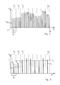
- 2 and 3 are an example of a path-dependent measurement method and using the example of a fictitious measured value curve, the recording and Evaluation method according to the invention in the diagrams presented in more detail explained.
- the abscissa axis of the diagrams shown in FIGS. 2 and 3 represents part of the distance S covered in FIG. 1 shown harvesting machine 1 during the work process.
- the The ordinate axis represents the cutting height H of the one shown in FIG. 1 Harvester 1.
- the measuring section S is located, starting at the starting point 7 of the work process, the current cutting height H mi is measured and stored periodically, at a distance ⁇ X, by the sensor 6.
- a measured value is represented symbolically by a bar, the length of a bar representing the amount of the measured value of the cutting height H mi .
- the continuous measurement values H mi are assigned to their associated interval class K 1 , K 2 , K 3 , ... K n .
- a mean value for example the arithmetic mean, H 1 , H 2 , H 3 to H N , which now represents the individual measured values H mi , its associated interval class K 1 , K 2 , K 3 , to K n this is assigned.
- the individual measured values H mi can then be deleted.
- the mean values of the cutting heights H 1 , H 2 , H 3 to H N are stored as representative of the individual measured values of the current cutting heights H mi
- the mean values H 1 , H 2 , H 3 to H N , the cutting height of the respective interval class K 1 , K 2 , K 3 , to K n are now in the form of the measuring distance S in FIG. 3 assigned to a bar chart and displayed.
- An average value as the average cutting height H 1 , H 2 , H 3 to H N is each represented symbolically by a bar, the length of a bar representing the amount of an average value H 1 , H 2 , H 3 to H N.
- a continuously averaged cutting height E 1 , E 2 , E 3 to E N can also be determined as the mean values of the mean values, which also continuously of the respective interval class K 1 , K 2 , K 3 until K n is assigned. These values indicate the current average cutting height until the respective interval class is reached.
- the value of the average cutting height E N last determined in the current work process thus always indicates the average value of the cutting height over the work process processed up to that point, calculated from the starting point 7.
- This value can continuously provide the driver of the harvesting machine 1 with a visual display in visualized form about the average cutting height E N achieved in the progressing harvesting process.
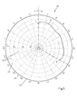
- 4 and 5 are basic exemplary embodiments for cutting height protocols 10 explained in a graphical representation.
- FIG. 4 shows a form of representation based on a Cartesian Coordinate system.
- FIG. 5 shows an illustration based on a polar Coordinate system.
- the time T is plotted on the abscissa, and the average cutting height E is plotted on the ordinate based on the function values as the average cutting height E 1 , E 2 , E 3 to E N.
- the course of the function graph 9 is defined by the values of the average cutting heights E 1 , E 2 , E 3 to E N.
- the radian as a time axis is on the circumference 13 of a full circle time T is defined.
- the full circle includes the time interval one Calendar day and is defined by a 24 scale.
- the average cutting height E is on the radius vectors of the polar coordinate system Length specifications, e.g. defined in centimeters. Concentric circles for The origin of the coordinates represent the equidistance lines 15 as line equals Cutting height H.
- the course of the function graph 9 is defined by the values of the average cutting heights E 1 , E 2 , E 3 to E N , these values characterizing the amount of the respective radius vector of the average cutting height H.
- the measuring points E 1 , E 2 , E 3 to E N are spaced apart from one another in time, the measuring points on the time axis can be represented at a distance from one another in such a way that they give the impression of an approximately closed curve purely optically.
- Another advantage of this evaluation method according to the invention is in that the individual measured value fluctuations as peaks, as for example in Pick up on the headlands or due to disturbances that a short-term Make it necessary to interrupt with lifting of the front attachment, none or hardly noticeable influence on the informative value of such a protocol have. This for the overall assessment of the average cutting height insignificant peaks lose their importance.
- More data as a parent variable which is also part of the Documentation process can be information about the Client and contractor, about the land name, the harvested good, about the driver, the make and type designation of the used Be a harvester. These can be the cutting height protocol according to FIG. 4 or complete Fig. 5 further.
- the cutting height as Process control variable in automatic mode in the sense of a control loop to be specified so that this can be adhered to.
- this documentation can also be found in Connected with a yield mapping GPS-based, thereby doing so
- exact terrestrial information on the harvested field is documented can be, which the informative value of the documentation improved ..
- the results of the measured values can either be on an internal or external data storage in the form of a log on board the harvester get saved. You can also directly on board the carrier vehicle suitable software on a monitor, e.g. on a display and Input unit 12 are mapped and also equally by means of a On-board printer are shown on a paper printout. Is too it is possible to save the data using a suitable data carrier. e.g. by means of a Floppy disk to an external computer to be transferred from this to be evaluated and printed out.
- the result can also be printed out there in paper form or for documentary purposes there on internal or external data storage digitized form can be saved in a corresponding file in the long term.
- the driver can use, for example, at least one evaluation unit 11 to determine the cutting height H, H mi , H 1 , H 2 , H 3 , H N , E 1 , E 2 , E 2 , E N , E N combined with a display and input unit 12 for visualization and editability of the determined cutting height H, H mi , H 1 , H 2 , H 3 , H N , (E 1 , E 2 , E 2 , E N ), E N are in operative connection.
- each work unit 3 can have a sensor 6 and an evaluation unit 11 for determining the cutting height with a display and input unit 12 for visualizing and editing the determined cutting heights H, H mi , H 1 , H 2 , H 3 , H N , (E 1 , E 2 , E 2 , E N ), E N can be assigned.
- Another advantage of the invention is that the contractor, for example a contractor, this documentation of the now due Can include billing as proof of the cutting height observed. On the other hand, the producer can also do this for his customer Cutting height achieved during the maize harvest in documented form prove.
- the average cutting height E N can be used on the basis of a cutting height log 10 in the sense of the invention as a documented assessment variable for the average cutting height H of a completed work process in the sense of an order.
Landscapes
- Life Sciences & Earth Sciences (AREA)
- Environmental Sciences (AREA)
- Engineering & Computer Science (AREA)
- Mechanical Engineering (AREA)
- Soil Sciences (AREA)
- Combines (AREA)
- Harvester Elements (AREA)
Abstract
Description
- 1
- Erntemaschine
- 2
- Vorsatzgerät
- 3
- Arbeitseinheit
- 4
- Feldhäcksler
- 5
- Fahrerkabine
- 6
- Sensor zur Schnitthöhenmessung
- 7
- Startpunkt
- 8
- Endpunkt
- 9
- Funktionsgraph
- 10
- Schnitthöhen-Protokoll
- 11
- Auswerteeinheit
- 12
- Anzeige und Eingabeeinheit
- 13
- Umfang
- 14
- Radius
- 15
- Äquidistanzlinie
- E1,E2,E2,EN
- fortlaufend gemittelte Schnitthöhe als Effektivschnitthöhe über die Mittelwerte der Intervall-Schnitthöhen
- F
- Fahrtrichtung
- H
- Schnitthöhe
- Hmi
- momentan gemessene Schnitthöhe im fortschreitenden Ernteprozess
- H1
- mittlere Schnitthöhe im 1. Intervall
- H2
- mittlere Schnitthöhe im 2. Intervall
- H3
- mittlere Schnitthöhe im 3. Intervall
- HN
- mittlere Schnitthöhe im n. Intervall
- K1
- 1. Intervallklasse
- K2
- 2. Intervallklasse
- K3
- 3. Intervallklasse
- KN
- n-te Intervallklasse
- S
- Messtrecke
- ΔS
- Intervallbreite
- T
- Zeit
- ΔX
- Messabstand
Claims (25)
- Verfahren zur Ermittlung von Daten zur Erstellung einer Dokumentation als Schnitthöhen-Protokoll während des laufenden Arbeitsprozesses einer Erntemaschine (1) mit zumindest einer Arbeitseinheit (3) zum Ernten von stängeligem Erntegut, dadurch gekennzeichnet, dass die momentane Schnitthöhe (Hmi) im laufenden Arbeitsprozess messtechnisch erfasst und fortlaufend gespeichert werden kann.
- Verfahren nach Anspruch 1, dadurch gekennzeichnet, dass die Messwerte der Schnitthöhen (Hmi) kumulativ erfasst und gespeichert werden.
- Verfahren nach Anspruch 1 und 2, dadurch gekennzeichnet, dass die kumulativ erfassten Messwerte (Hmi) zur Bildung von Mittelwerten (H1,H2,H3,HN), (E1,E2,E2,EN) bezüglich der Schnitthöhe (H) genutzt werden.
- Verfahren nach einem oder mehreren der vorhergehenden Ansprüche, dadurch gekennzeichnet, dass die Messwerte (Hmi) Intervallklassen (K1 K2 K3 bis KN) zugeordnet werden.
- Verfahren nach einem oder mehreren der vorhergehenden Ansprüche, dadurch gekennzeichnet, dass die kumulierten Messwerte (Hmi) einer Intervallklasse (K1,K2,K3,bis Kn) zur Bildung einer mittleren Schnitthöhe (H1,H2,H3,HN) als Mittelwert der jeweiligen Intervallklasse (K1,K2,K3, bis Kn) genutzt werden.
- Verfahren nach einem oder mehreren der vorhergehenden Ansprüche, dadurch gekennzeichnet, dass die Beträge der mittleren Schnitthöhe (H1,H2,H3,HN) der jeweiligen Intervallklasse (K1,K2,K3,bis Kn) zugeordnet, fortlaufend gespeichert werden.
- Verfahren nach einem oder mehreren der vorhergehenden Ansprüche, dadurch gekennzeichnet, dass die Beträge der mittleren Schnitthöhe (H1,H2,H3,HN) erfasst und fortlaufend gespeichert werden.
- Verfahren nach einem oder mehreren der vorhergehenden Ansprüche, dadurch gekennzeichnet, dass die Anzahl der Messpunkte der momentanen Schnitthöhe (Hmi) und/oder die Anzahl der gebildeten Intervallklassen (K1,K2,K3,KN) momentan erfasst und fortlaufend gespeichert werden.
- Verfahren nach einem oder mehreren der vorhergehenden Ansprüche, dadurch gekennzeichnet, dass die Schnitthöhen (Hmi) und/oder (H1,H2,H3, bis HN) zur fortlaufenden Mittelwertbildung der gemittelten Schnitthöhe (E1,E2,E2, bis EN) genutzt werden.
- Verfahren nach einem oder mehreren der vorhergehenden Ansprüche, dadurch gekennzeichnet, dass die Beträge der gemittelten Schnitthöhe (E1,E2,E2, bis EN) fortlaufend ermittelt und gespeichert werden.
- Verfahren nach einem oder mehreren der vorhergehenden Ansprüche, dadurch gekennzeichnet, dass der im laufenden Arbeitsprozess ermittelte Wert der gemittelten Schnitthöhe (EN) die momentane mittelte Schnitthöhe (H) des Arbeitsfortschritts von Beginn des Startpunkts (7) an darstellt.
- Verfahren nach einem oder mehreren der vorhergehenden Ansprüche, dadurch gekennzeichnet, dass die ermittelten Messwerte (H1,H2,H3 bis ,HN) und/oder (E1,E2,E3, bis EN) in digitalisierter Form abrufbar gespeichert werden.
- Verfahren nach einem oder mehreren der vorhergehenden Ansprüche, dadurch gekennzeichnet, dass die gebildeten Messwerte (Hmi) hinsichtlich des Schnitthöhenverlaufs sensorisch mit Messwertgebern mit analogem oder digitalem Ausgangssignal erfasst werden.
- Verfahren nach einem oder mehreren der vorhergehenden Ansprüche, dadurch gekennzeichnet, dass die gebildeten Messwerte (Hmi) wegabhängig erfasst und gespeichert werden.
- Verfahren nach einem oder mehreren der vorhergehenden Ansprüche, dadurch gekennzeichnet, dass die gebildeten Messwerte (Hmi) zeitabhängig erfasst und gespeichert werden.
- Verfahren nach einem oder mehreren der vorhergehenden Ansprüche, dadurch gekennzeichnet, dass die mittlere Schnitthöhe (EN) über die Schnitthöhe (Hmi) während des Arbeitsprozesses fortlaufend und visualisiert am Arbeitsplatz des Fahrers angezeigt werden kann.
- Verfahren nach einem oder mehreren der vorhergehenden Ansprüche, dadurch gekennzeichnet, dass ein Schnitthöhenprotokoll (10) durch Betriebserfassungsdaten der Erntemaschine (1) und/oder Auftraggeberund Auftragnehmerdaten ergänzt werden kann.
- Verfahren nach einem oder mehreren der vorhergehenden Ansprüche, dadurch gekennzeichnet, dass das Schnitthöhenprotokoll (10) an Bord der Erntemaschine (1) speicherbar abgerufen und ausgelesen werden kann.
- Verfahren nach einem oder mehreren der vorhergehenden Ansprüche, dadurch gekennzeichnet, dass das Schnitthöhenprotokoll über den Weg und/oder die Zeit als Mittelwert-Graph (9) auf einem Monitor an Bord der Erntemaschine (1) darstellbar ist.
- Verfahren nach einem oder mehreren der vorhergehenden Ansprüche, dadurch gekennzeichnet, dass das Schnitthöhenprotokoll über den Weg und/oder die Zeit als Mittelwert-Graph (9) als Papierausdruck an Bord der Erntemaschine (1) abrufbar ausgelesen werden kann.
- Verfahren nach einem oder mehreren der vorhergehenden Ansprüche, dadurch gekennzeichnet, dass ein Schnitthöhenprotokoll (10) in Verbindung mit eine GPS-Gestützten Ertragskartierung gespeichert und/oder abrufbar und/oder ausgelesen werden kann.
- Verfahren nach einem oder mehreren der vorhergehenden Ansprüche, dadurch gekennzeichnet, dass die gemittelte Schnitthöhe (EN) auf der Basis einen Schnitthöhen-Protokolls (10) als Beurteilungsgröße für die durchschnittliche Schnitthöhe (H) eines abgeschlossenen Arbeitsprozesses herangezogen werden kann.
- Erntemaschine zur Anwendung des Verfahrens nach einem oder mehreren der vorhergehenden Ansprüche, dadurch gekennzeichnet, dass der Fahrer über zumindest eine Auswerteeinheit (11) zur Ermittlung der Schnitthöhe (H) mit einer Anzeige- und Eingabeeinheit (12) zur Visualisierung und Editierbarkeit der ermittelten Schnitthöhen (H), in Wirkverbindung steht.
- Erntemaschine zur Anwendung des Verfahrens nach einem oder mehreren der vorhergehenden Ansprüche, dadurch gekennzeichnet, dass die landwirtschaftliche Erntemaschine (1) eine Vielzahl von Arbeitseinheiten (3) aufnimmt und jeder Arbeitseinheit (3) zumindest einen Sensor (6) und eine Auswerteeinheit (11) zur Ermittlung der Schnitthöhe (H) mit einer Anzeigeund Eingabeeinheit (12) zur Visualisierung und Editierbarkeit der ermittelten Schnitthöhen (H) zugeordnet ist.
- Erntemaschine zur Anwendung des Verfahrens nach einem oder mehreren der vorhergehenden Ansprüche, dadurch gekennzeichnet, dass die Erntemaschine (1) einen Maishäcksler, einen Mähdrescher oder ein selbstfahrendes Mähwerk umfasst.
Applications Claiming Priority (2)
| Application Number | Priority Date | Filing Date | Title |
|---|---|---|---|
| DE10225098A DE10225098A1 (de) | 2002-06-05 | 2002-06-05 | Verfahren zur Erstellung eines Schnitthöhen-Protokolls im laufenden Arbeitsprozess von Erntemaschinen |
| DE10225098 | 2002-06-05 |
Publications (2)
| Publication Number | Publication Date |
|---|---|
| EP1369020A1 true EP1369020A1 (de) | 2003-12-10 |
| EP1369020B1 EP1369020B1 (de) | 2005-11-09 |
Family
ID=29432670
Family Applications (1)
| Application Number | Title | Priority Date | Filing Date |
|---|---|---|---|
| EP03012706A Expired - Lifetime EP1369020B1 (de) | 2002-06-05 | 2003-06-04 | Verfahren zur Erstellung eines Schnitthöhenprotokolls im laufenden Arbeitsprozess von Erntemaschinen |
Country Status (3)
| Country | Link |
|---|---|
| EP (1) | EP1369020B1 (de) |
| AT (1) | ATE308875T1 (de) |
| DE (2) | DE10225098A1 (de) |
Cited By (1)
| Publication number | Priority date | Publication date | Assignee | Title |
|---|---|---|---|---|
| EP4197312A1 (de) * | 2021-12-20 | 2023-06-21 | Deere & Company | Erntegutbestandteile, prädiktive kartierung und steuerung einer landwirtschaftlichen erntemaschine |
Families Citing this family (3)
| Publication number | Priority date | Publication date | Assignee | Title |
|---|---|---|---|---|
| DE102004038404B4 (de) | 2004-08-07 | 2021-01-07 | Deere & Company | Einrichtung zur selbsttätigen Einstellung der Schnitthöhe eines Erntevorsatzes zur Ernte stängelartiger Pflanzen |
| DE102007042295A1 (de) * | 2007-09-06 | 2009-03-12 | Volkswagen Ag | Verfahren und Vorrichtung zur Anzeige von Emissionen eines Kraftfahrzeuges |
| DE102008049009A1 (de) * | 2008-09-25 | 2010-04-01 | Dr. Ing. H.C. F. Porsche Aktiengesellschaft | Anzeigeeinrichtung |
Citations (3)
| Publication number | Priority date | Publication date | Assignee | Title |
|---|---|---|---|---|
| US5524424A (en) * | 1994-12-13 | 1996-06-11 | Case Corporation | Electronic area counter for a combine |
| US5978720A (en) * | 1993-12-08 | 1999-11-02 | Claas Ohg | Agricultural machine, especially combine harvester, with multi-processor guide system |
| US6272819B1 (en) * | 1998-11-17 | 2001-08-14 | Case Corporation | Sugar cane yield monitor |
-
2002
- 2002-06-05 DE DE10225098A patent/DE10225098A1/de not_active Withdrawn
-
2003
- 2003-06-04 EP EP03012706A patent/EP1369020B1/de not_active Expired - Lifetime
- 2003-06-04 AT AT03012706T patent/ATE308875T1/de active
- 2003-06-04 DE DE50301593T patent/DE50301593D1/de not_active Expired - Lifetime
Patent Citations (3)
| Publication number | Priority date | Publication date | Assignee | Title |
|---|---|---|---|---|
| US5978720A (en) * | 1993-12-08 | 1999-11-02 | Claas Ohg | Agricultural machine, especially combine harvester, with multi-processor guide system |
| US5524424A (en) * | 1994-12-13 | 1996-06-11 | Case Corporation | Electronic area counter for a combine |
| US6272819B1 (en) * | 1998-11-17 | 2001-08-14 | Case Corporation | Sugar cane yield monitor |
Cited By (2)
| Publication number | Priority date | Publication date | Assignee | Title |
|---|---|---|---|---|
| EP4197312A1 (de) * | 2021-12-20 | 2023-06-21 | Deere & Company | Erntegutbestandteile, prädiktive kartierung und steuerung einer landwirtschaftlichen erntemaschine |
| US12302791B2 (en) | 2021-12-20 | 2025-05-20 | Deere & Company | Crop constituents, predictive mapping, and agricultural harvester control |
Also Published As
| Publication number | Publication date |
|---|---|
| DE10225098A1 (de) | 2003-12-18 |
| EP1369020B1 (de) | 2005-11-09 |
| ATE308875T1 (de) | 2005-11-15 |
| DE50301593D1 (de) | 2005-12-15 |
Similar Documents
| Publication | Publication Date | Title |
|---|---|---|
| EP3456167B1 (de) | Landwirtschaftliche arbeitsmaschine | |
| DE60215124T2 (de) | Verfahren zur optimierung von ernteertragsabbildung | |
| CN104737214B (zh) | 联合收割机、以及联合收割机管理系统 | |
| DE4322293C2 (de) | Verfahren zum elektronischen Managen von landwirtschaftlichen Maschinen | |
| DE60132018T2 (de) | Verfahren zur schätzung des ernteertrages | |
| DE10306726A1 (de) | Methode zur Optimierung von einstellbaren Parametern | |
| DE102008061252A1 (de) | Verfahren zur Unterstützung der Automatisierung landwirtschaftlicher Leistungen | |
| EP3707988A1 (de) | Verfahren zum betreiben einer erntemaschine mit hilfe eines pflanzenwachstumsmodells | |
| DE112014000918T5 (de) | Ernteguterfassungsanzeige | |
| DE112014000906T5 (de) | Pflanzenweise Ernteguterfassungsauflösung | |
| DE102021107320A1 (de) | Informationenbereitstellungsvorrichtung, mähfahrzeug und mähverwaltungssystem | |
| DE102019121052A1 (de) | Verfahren zur Ertragskartierung | |
| DE102015114568A1 (de) | Verfahren zum Betreiben von landwirtschaftlichen Arbeitsmaschinen | |
| EP2197171A2 (de) | Verfahren zur Unterstützung der Automatisierung landwirtschaftlicher Leistungen | |
| DE69631148T2 (de) | Schlepper mit überwachungssystem | |
| EP1369020B1 (de) | Verfahren zur Erstellung eines Schnitthöhenprotokolls im laufenden Arbeitsprozess von Erntemaschinen | |
| DE102020125434A1 (de) | Landwirtschaftliche Maschine mit NIR-Sensor und Datenverarbeitungssystem | |
| EP2130422B1 (de) | Selbstfahrendes Fahrzeug zur Bearbeitung landwirtschaftlicher Flächen und Verfahren zum Betreiben eines selbstfahrenden Fahrzeugs zur Bearbeitung landwirtschaftlicher Flächen | |
| EP1900272A1 (de) | Anzeigeeinheit einer landwirtschaftlichen Arbeitsmaschine | |
| EP3974810A1 (de) | Nir-sensor-kalibriermethode | |
| DE102017127648B3 (de) | Landwirtschaftsmaschine sowie Verfahren zum Betreiben einer solchen Maschine | |
| EP4310744A1 (de) | Assistenzsystem zur ernteunterstützung | |
| Andrade-Sanchez et al. | Yield monitoring technology for irrigated cotton and grains in Arizona: hardware and software selection | |
| EP3258431A1 (de) | Verfahren zur zustandsakquisition einer landwirtschaftlichen arbeitseinheit | |
| DE10154874A1 (de) | Durchsatzmeßvorrichtung in einer Erntemaschine |
Legal Events
| Date | Code | Title | Description |
|---|---|---|---|
| PUAI | Public reference made under article 153(3) epc to a published international application that has entered the european phase |
Free format text: ORIGINAL CODE: 0009012 |
|
| AK | Designated contracting states |
Kind code of ref document: A1 Designated state(s): AT BE BG CH CY CZ DE DK EE ES FI FR GB GR HU IE IT LI LU MC NL PT RO SE SI SK TR |
|
| AX | Request for extension of the european patent |
Extension state: AL LT LV MK |
|
| 17P | Request for examination filed |
Effective date: 20040611 |
|
| AKX | Designation fees paid |
Designated state(s): AT BE BG CH CY CZ DE DK EE ES FI FR GB GR HU IE IT LI LU MC NL PT RO SE SI SK TR |
|
| 17Q | First examination report despatched |
Effective date: 20040817 |
|
| GRAP | Despatch of communication of intention to grant a patent |
Free format text: ORIGINAL CODE: EPIDOSNIGR1 |
|
| GRAS | Grant fee paid |
Free format text: ORIGINAL CODE: EPIDOSNIGR3 |
|
| GRAA | (expected) grant |
Free format text: ORIGINAL CODE: 0009210 |
|
| AK | Designated contracting states |
Kind code of ref document: B1 Designated state(s): AT BE BG CH CY CZ DE DK EE ES FI FR GB GR HU IE IT LI LU MC NL PT RO SE SI SK TR |
|
| PG25 | Lapsed in a contracting state [announced via postgrant information from national office to epo] |
Ref country code: SK Free format text: LAPSE BECAUSE OF FAILURE TO SUBMIT A TRANSLATION OF THE DESCRIPTION OR TO PAY THE FEE WITHIN THE PRESCRIBED TIME-LIMIT Effective date: 20051109 Ref country code: SI Free format text: LAPSE BECAUSE OF FAILURE TO SUBMIT A TRANSLATION OF THE DESCRIPTION OR TO PAY THE FEE WITHIN THE PRESCRIBED TIME-LIMIT Effective date: 20051109 Ref country code: CZ Free format text: LAPSE BECAUSE OF FAILURE TO SUBMIT A TRANSLATION OF THE DESCRIPTION OR TO PAY THE FEE WITHIN THE PRESCRIBED TIME-LIMIT Effective date: 20051109 Ref country code: RO Free format text: LAPSE BECAUSE OF FAILURE TO SUBMIT A TRANSLATION OF THE DESCRIPTION OR TO PAY THE FEE WITHIN THE PRESCRIBED TIME-LIMIT Effective date: 20051109 Ref country code: FI Free format text: LAPSE BECAUSE OF FAILURE TO SUBMIT A TRANSLATION OF THE DESCRIPTION OR TO PAY THE FEE WITHIN THE PRESCRIBED TIME-LIMIT Effective date: 20051109 |
|
| REG | Reference to a national code |
Ref country code: GB Ref legal event code: FG4D Free format text: NOT ENGLISH |
|
| REG | Reference to a national code |
Ref country code: CH Ref legal event code: EP |
|
| REG | Reference to a national code |
Ref country code: IE Ref legal event code: FG4D Free format text: LANGUAGE OF EP DOCUMENT: GERMAN |
|
| REF | Corresponds to: |
Ref document number: 50301593 Country of ref document: DE Date of ref document: 20051215 Kind code of ref document: P |
|
| GBT | Gb: translation of ep patent filed (gb section 77(6)(a)/1977) |
Effective date: 20060111 |
|
| PG25 | Lapsed in a contracting state [announced via postgrant information from national office to epo] |
Ref country code: SE Free format text: LAPSE BECAUSE OF FAILURE TO SUBMIT A TRANSLATION OF THE DESCRIPTION OR TO PAY THE FEE WITHIN THE PRESCRIBED TIME-LIMIT Effective date: 20060209 Ref country code: GR Free format text: LAPSE BECAUSE OF FAILURE TO SUBMIT A TRANSLATION OF THE DESCRIPTION OR TO PAY THE FEE WITHIN THE PRESCRIBED TIME-LIMIT Effective date: 20060209 Ref country code: DK Free format text: LAPSE BECAUSE OF FAILURE TO SUBMIT A TRANSLATION OF THE DESCRIPTION OR TO PAY THE FEE WITHIN THE PRESCRIBED TIME-LIMIT Effective date: 20060209 Ref country code: BG Free format text: LAPSE BECAUSE OF FAILURE TO SUBMIT A TRANSLATION OF THE DESCRIPTION OR TO PAY THE FEE WITHIN THE PRESCRIBED TIME-LIMIT Effective date: 20060209 |
|
| PG25 | Lapsed in a contracting state [announced via postgrant information from national office to epo] |
Ref country code: ES Free format text: LAPSE BECAUSE OF FAILURE TO SUBMIT A TRANSLATION OF THE DESCRIPTION OR TO PAY THE FEE WITHIN THE PRESCRIBED TIME-LIMIT Effective date: 20060220 |
|
| REG | Reference to a national code |
Ref country code: HU Ref legal event code: AG4A Ref document number: E000198 Country of ref document: HU |
|
| PG25 | Lapsed in a contracting state [announced via postgrant information from national office to epo] |
Ref country code: PT Free format text: LAPSE BECAUSE OF FAILURE TO SUBMIT A TRANSLATION OF THE DESCRIPTION OR TO PAY THE FEE WITHIN THE PRESCRIBED TIME-LIMIT Effective date: 20060410 |
|
| PG25 | Lapsed in a contracting state [announced via postgrant information from national office to epo] |
Ref country code: MC Free format text: LAPSE BECAUSE OF NON-PAYMENT OF DUE FEES Effective date: 20060630 |
|
| ET | Fr: translation filed | ||
| PLBE | No opposition filed within time limit |
Free format text: ORIGINAL CODE: 0009261 |
|
| STAA | Information on the status of an ep patent application or granted ep patent |
Free format text: STATUS: NO OPPOSITION FILED WITHIN TIME LIMIT |
|
| 26N | No opposition filed |
Effective date: 20060810 |
|
| REG | Reference to a national code |
Ref country code: CH Ref legal event code: PL |
|
| PG25 | Lapsed in a contracting state [announced via postgrant information from national office to epo] |
Ref country code: LI Free format text: LAPSE BECAUSE OF NON-PAYMENT OF DUE FEES Effective date: 20070630 Ref country code: CH Free format text: LAPSE BECAUSE OF NON-PAYMENT OF DUE FEES Effective date: 20070630 |
|
| PG25 | Lapsed in a contracting state [announced via postgrant information from national office to epo] |
Ref country code: EE Free format text: LAPSE BECAUSE OF FAILURE TO SUBMIT A TRANSLATION OF THE DESCRIPTION OR TO PAY THE FEE WITHIN THE PRESCRIBED TIME-LIMIT Effective date: 20051109 |
|
| PG25 | Lapsed in a contracting state [announced via postgrant information from national office to epo] |
Ref country code: LU Free format text: LAPSE BECAUSE OF NON-PAYMENT OF DUE FEES Effective date: 20060604 Ref country code: TR Free format text: LAPSE BECAUSE OF FAILURE TO SUBMIT A TRANSLATION OF THE DESCRIPTION OR TO PAY THE FEE WITHIN THE PRESCRIBED TIME-LIMIT Effective date: 20051109 |
|
| PG25 | Lapsed in a contracting state [announced via postgrant information from national office to epo] |
Ref country code: CY Free format text: LAPSE BECAUSE OF FAILURE TO SUBMIT A TRANSLATION OF THE DESCRIPTION OR TO PAY THE FEE WITHIN THE PRESCRIBED TIME-LIMIT Effective date: 20051109 |
|
| PGFP | Annual fee paid to national office [announced via postgrant information from national office to epo] |
Ref country code: IE Payment date: 20140625 Year of fee payment: 12 |
|
| PGFP | Annual fee paid to national office [announced via postgrant information from national office to epo] |
Ref country code: NL Payment date: 20140618 Year of fee payment: 12 Ref country code: AT Payment date: 20140611 Year of fee payment: 12 |
|
| PGFP | Annual fee paid to national office [announced via postgrant information from national office to epo] |
Ref country code: HU Payment date: 20140618 Year of fee payment: 12 |
|
| REG | Reference to a national code |
Ref country code: AT Ref legal event code: MM01 Ref document number: 308875 Country of ref document: AT Kind code of ref document: T Effective date: 20150604 |
|
| REG | Reference to a national code |
Ref country code: NL Ref legal event code: MM Effective date: 20150701 |
|
| REG | Reference to a national code |
Ref country code: IE Ref legal event code: MM4A |
|
| PG25 | Lapsed in a contracting state [announced via postgrant information from national office to epo] |
Ref country code: NL Free format text: LAPSE BECAUSE OF NON-PAYMENT OF DUE FEES Effective date: 20150701 Ref country code: IE Free format text: LAPSE BECAUSE OF NON-PAYMENT OF DUE FEES Effective date: 20150604 |
|
| PG25 | Lapsed in a contracting state [announced via postgrant information from national office to epo] |
Ref country code: HU Free format text: LAPSE BECAUSE OF NON-PAYMENT OF DUE FEES Effective date: 20150605 Ref country code: AT Free format text: LAPSE BECAUSE OF NON-PAYMENT OF DUE FEES Effective date: 20150604 |
|
| REG | Reference to a national code |
Ref country code: FR Ref legal event code: PLFP Year of fee payment: 14 |
|
| REG | Reference to a national code |
Ref country code: FR Ref legal event code: PLFP Year of fee payment: 15 |
|
| PGFP | Annual fee paid to national office [announced via postgrant information from national office to epo] |
Ref country code: DE Payment date: 20170621 Year of fee payment: 15 Ref country code: GB Payment date: 20170620 Year of fee payment: 15 Ref country code: FR Payment date: 20170621 Year of fee payment: 15 |
|
| PGFP | Annual fee paid to national office [announced via postgrant information from national office to epo] |
Ref country code: IT Payment date: 20170622 Year of fee payment: 15 Ref country code: BE Payment date: 20170620 Year of fee payment: 15 |
|
| REG | Reference to a national code |
Ref country code: DE Ref legal event code: R119 Ref document number: 50301593 Country of ref document: DE |
|
| GBPC | Gb: european patent ceased through non-payment of renewal fee |
Effective date: 20180604 |
|
| REG | Reference to a national code |
Ref country code: BE Ref legal event code: MM Effective date: 20180630 |
|
| PG25 | Lapsed in a contracting state [announced via postgrant information from national office to epo] |
Ref country code: IT Free format text: LAPSE BECAUSE OF NON-PAYMENT OF DUE FEES Effective date: 20180604 Ref country code: DE Free format text: LAPSE BECAUSE OF NON-PAYMENT OF DUE FEES Effective date: 20190101 Ref country code: FR Free format text: LAPSE BECAUSE OF NON-PAYMENT OF DUE FEES Effective date: 20180630 Ref country code: GB Free format text: LAPSE BECAUSE OF NON-PAYMENT OF DUE FEES Effective date: 20180604 |
|
| PG25 | Lapsed in a contracting state [announced via postgrant information from national office to epo] |
Ref country code: BE Free format text: LAPSE BECAUSE OF NON-PAYMENT OF DUE FEES Effective date: 20180630 |
|
| P01 | Opt-out of the competence of the unified patent court (upc) registered |
Effective date: 20230511 |