EP1369000B1 - Verfahren zur herstellung einer verbundelektrode für einen lichtbogen-plasmabrenner - Google Patents
Verfahren zur herstellung einer verbundelektrode für einen lichtbogen-plasmabrenner Download PDFInfo
- Publication number
- EP1369000B1 EP1369000B1 EP02713801A EP02713801A EP1369000B1 EP 1369000 B1 EP1369000 B1 EP 1369000B1 EP 02713801 A EP02713801 A EP 02713801A EP 02713801 A EP02713801 A EP 02713801A EP 1369000 B1 EP1369000 B1 EP 1369000B1
- Authority
- EP
- European Patent Office
- Prior art keywords
- electrode
- silver
- welding
- mating surface
- forward portion
- Prior art date
- Legal status (The legal status is an assumption and is not a legal conclusion. Google has not performed a legal analysis and makes no representation as to the accuracy of the status listed.)
- Expired - Lifetime
Links
Images


Classifications
-
- H—ELECTRICITY
- H05—ELECTRIC TECHNIQUES NOT OTHERWISE PROVIDED FOR
- H05H—PLASMA TECHNIQUE; PRODUCTION OF ACCELERATED ELECTRICALLY-CHARGED PARTICLES OR OF NEUTRONS; PRODUCTION OR ACCELERATION OF NEUTRAL MOLECULAR OR ATOMIC BEAMS
- H05H1/00—Generating plasma; Handling plasma
- H05H1/24—Generating plasma
- H05H1/26—Plasma torches
- H05H1/32—Plasma torches using an arc
- H05H1/34—Details, e.g. electrodes, nozzles
- H05H1/3436—Hollow cathodes with internal coolant flow
-
- H—ELECTRICITY
- H05—ELECTRIC TECHNIQUES NOT OTHERWISE PROVIDED FOR
- H05H—PLASMA TECHNIQUE; PRODUCTION OF ACCELERATED ELECTRICALLY-CHARGED PARTICLES OR OF NEUTRONS; PRODUCTION OR ACCELERATION OF NEUTRAL MOLECULAR OR ATOMIC BEAMS
- H05H1/00—Generating plasma; Handling plasma
- H05H1/24—Generating plasma
- H05H1/26—Plasma torches
- H05H1/32—Plasma torches using an arc
- H05H1/34—Details, e.g. electrodes, nozzles
-
- B—PERFORMING OPERATIONS; TRANSPORTING
- B23—MACHINE TOOLS; METAL-WORKING NOT OTHERWISE PROVIDED FOR
- B23K—SOLDERING OR UNSOLDERING; WELDING; CLADDING OR PLATING BY SOLDERING OR WELDING; CUTTING BY APPLYING HEAT LOCALLY, e.g. FLAME CUTTING; WORKING BY LASER BEAM
- B23K20/00—Non-electric welding by applying impact or other pressure, with or without the application of heat, e.g. cladding or plating
- B23K20/12—Non-electric welding by applying impact or other pressure, with or without the application of heat, e.g. cladding or plating the heat being generated by friction; Friction welding
- B23K20/129—Non-electric welding by applying impact or other pressure, with or without the application of heat, e.g. cladding or plating the heat being generated by friction; Friction welding specially adapted for particular articles or workpieces
-
- B—PERFORMING OPERATIONS; TRANSPORTING
- B23—MACHINE TOOLS; METAL-WORKING NOT OTHERWISE PROVIDED FOR
- B23K—SOLDERING OR UNSOLDERING; WELDING; CLADDING OR PLATING BY SOLDERING OR WELDING; CUTTING BY APPLYING HEAT LOCALLY, e.g. FLAME CUTTING; WORKING BY LASER BEAM
- B23K35/00—Rods, electrodes, materials, or media, for use in soldering, welding, or cutting
- B23K35/02—Rods, electrodes, materials, or media, for use in soldering, welding, or cutting characterised by mechanical features, e.g. shape
- B23K35/0211—Rods, electrodes, materials, or media, for use in soldering, welding, or cutting characterised by mechanical features, e.g. shape for use in cutting
- B23K35/0216—Rods, electrodes, wires
-
- H—ELECTRICITY
- H05—ELECTRIC TECHNIQUES NOT OTHERWISE PROVIDED FOR
- H05H—PLASMA TECHNIQUE; PRODUCTION OF ACCELERATED ELECTRICALLY-CHARGED PARTICLES OR OF NEUTRONS; PRODUCTION OR ACCELERATION OF NEUTRAL MOLECULAR OR ATOMIC BEAMS
- H05H1/00—Generating plasma; Handling plasma
- H05H1/24—Generating plasma
- H05H1/26—Plasma torches
- H05H1/32—Plasma torches using an arc
- H05H1/34—Details, e.g. electrodes, nozzles
- H05H1/3442—Cathodes with inserted tip
Definitions
- the present invention relates to a method of manufacturing a composite electrode for a plasma arc torch, in particular, a composite electrode for a plasma arc torch in which a forward portion of the electrode body comprises a first metallic material having high thermal conductivity and the remaining aft portion of the electrode body comprises a second low cost, metallic material with good thermal and electrical conductivity.
- a plasma torch generally includes an electrode mounted therein, a nozzle with a central exit orifice mounted within a torch body, electrical connections, passages for cooling and arc control fluids, a swirl ring to control fluid flow patterns in the plasma chamber formed between the electrode and nozzle, and a power supply.
- the torch produces a plasma arc, which is a constricted ionized jet of a plasma gas with high temperature and high momentum.
- Gases used in the torch can be non-reactive (e.g. argon or nitrogen), or reactive (e.g. oxygen or air).
- a pilot arc is first generated between the electrode (cathode) and the nozzle (anode).
- Generation of the pilot arc may be by means of a high frequency, high voltage signal coupled to a DC power supply and the torch or any of a variety of contact starting methods.
- an electrode for a plasma arc torch includes an emitting insert (e.g., hafnium) which is press fit into a bore in the electrode.
- An objective in electrode design is to transfer heat from the hafnium insert and into a cooling medium, which is usually water.
- Another objective is to control arc root attachment to minimize erosion caused by undesirable arc root attachment to the electrode instead of the hafnium insert.
- Electrodes for plasma arc torches are commonly made from copper. Copper is a low cost material that offers good thermal and electrical conductivity. Electrodes for plasma arc torches can also be made from silver. While silver electrodes provide excellent heat transfer characteristics, they tend to be very expensive and not cost effective to use. Copper electrodes are cost effective, but do not have the superior heat transfer characteristics of a silver electrode and thus have a shorter electrode life than silver electrodes.
- silver and silver/copper composite electrodes using a variety of manufacturing techniques including brazing, soldering, swaging, press fitting and other methods.
- One company has developed a vacuum brazed copper/silver composite design with a through-hole hafnium insert (such as part number C10-963 manufactured by Centricut of New Hampshire, USA for the PT - 15XL torch).
- Another company has developed a press-fitted silver annulus design with a blind hole hafnium insert ( US 5, 023, 452 ).
- Another company has developed a swaged silver annulus design in a copper holder with copper on the front portion ( US 5, 767, 478 ).
- Another company has developed coined silver electrode design such as the K2XL cathode manufactured by Kjellberg of Germany US 5 628 924 shows soldering, press-fitting and diffusion bonding as joining techniques for silver with copper.
- these methods of manufacturing silver/copper electrodes do not produce a sufficiently high-strength joint at the silver/copper interface.
- these manufacturing methods result in electrodes that can leak cooling fluid at the silver/copper interface. More significantly, these silver/composite electrodes do not offer the heat transfer characteristics of an all silver electrode.
- Another object of the present invention is to provide a method of manufacturing an improved composite electrode that does not leak cooling fluid.
- the present invention provides a method of manufacturing an electrode as defined in claim 1.
- the torch includes a torch body having a nozzle amounted relative to a composite electrode in the body to define a plasma chamber.
- the torch body includes a plasma flow path for directing a plasma gas to the plasma chamber.
- the torch can also include a shield attached to the torch body.
- the nozzle, composite electrode and shield are consumable parts that wear out and require periodic replacement
- the composite electrode has two portions made from different material.
- the forward portion of the electrode comprises a metallic material with excellent heat transfer properties (e.g., high thermal conductivity) (e.g., silver).
- An emissive insert e.g., hafnium, zirconium, tungsten, thorium, lanthanum, strontium, or alloys thereof
- the aft portion of the electrode comprises a low cost, metallic material with good heat transfer properties (e.g., good thermal conductivity) (e.g., copper).
- the high thermal conductivity, forward portion is joined onto an end of the good thermal conductivity, aft portion to form the composite electrode.
- the two portions are joined by a direct welding process including at least one of friction welding, inertia friction welding; direct drive friction welding, CD percussive welding, percussive welding, ultrasonic welding, or explosion welding, that forms a hermetic seal between the two portions of the electrode.
- the forward portion also extends back to the area of cooling fluid flow and is therefore directly cooled by the fluid.
- This construction in contrast to known electrode designs having a relatively small diameter, high thermal conductivity sleeve inserted into a cavity formed in the front end for surrounding an emissive insert, is believed to provide an electrode that has superior heat transfer properties and does not leak cooling fluid.
- the composite electrode includes a forward portion comprising a metallic material with excellent heat transfer material properties (e.g., high thermal conductivity) (e.g., silver):
- the aft portion of the electrode comprises a low cost, metallic material with good heat transfer material properties (e.g., good thermal conductivity) (e.g., copper).
- the high thermal conductivity, forward portion is joined onto an end of the good thermal conductivity, aft portion to form the composite electrode.
- the forward and aft portions are in direct contact at the mating surface.
- the two portions are joined together by a direct welding technique including at least one of friction welding, inertia friction welding, direct drive friction welding, CD percussive welding, percussive welding, ultrasonic welding, or explosion welding.
- the direct welding process forms a high strength, hermetic seal between the two portions of the electrode.
- the forward portion also extends back to the area of cooling fluid flow and is therefore directly cooled by the fluid.
- the present claimed invention features a method of manufacturing an electrode for cutting or marking a workpiece.
- An electrode is provided including a forward portion comprising a metallic material with excellent heat transfer material properties (e.g., high thermal conductivity) (e.g., silver).
- An aft portion of the electrode body is also provided, comprising a low cost, metallic material with good heat transfer material properties (e.g., good thermal conductivity (e.g., copper).
- the two portions of the electrode are joined by a direct welding technique.
- the direct welding technique includes at least one of friction welding, inertia friction welding, direct drive friction welding, CD percussive welding, percussive welding, ultrasonic welding, or explosion welding, thereby forming a high strength, hermetic seal between the forward and aft portions of the electrode.
- Cooling fluid flow can be used to cool the forward portion of the electrode, and an insert with high thermionic emissivity can be located in a bore in the forward portion of the electrode body.
- FIG. 1 is a cross-sectional view of one embodiment of a plasma arc torch
- FIG. 1A is a cross-sectional view of one embodiment of a composite electrode for use in the plasma arc torch of FIG. 1 .
- FIG. 2 is a cross-sectional view of another embodiment of a composite electrode for use in the plasma arc torch of FIG. 1 .
- FIG. 3 is a graph comparing the number of starts vs. pit wear from various electrode configurations.
- FIG. 4 is a graph comparing the performance of electrodes made according to the present invention with other electrodes, using 4 second testing.
- FIG. 5 is a graph comparing the performance of electrodes made according to the present invention with other electrodes, using 60 second testing.
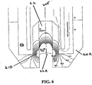
- FIG. 6 is a graphical representation showing a temperature contour plot in a model, of a silver tip electrode during torch operation, based on a computational fluid dynamics model.
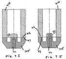
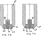
- FIG.'s 7A-7Q show various embodiments of electrode tip configurations of the invention.
- FIG. 7R shows an aft portion of an electrode having a receiving portion.
- FIG. 1 shows a plasma arc torch 10 embodying the principles of the invention.
- the torch has a body 12, which is typically cylindrical with an exit orifice 14 at a lower end 16.
- a plasma arc 18, i.e. an ionized gas jet passes through the exit orifice and attaches to a workpiece 19 being cut.
- the torch is designed to pierce, cut, or mark metal, particularly mild steel, or other materials in a transferred arc mode. In cutting mild steel, the torch operates with a reactive gas, such as oxygen or air, as the plasma gas to form the transferred plasma arc 18.
- a reactive gas such as oxygen or air
- the torch body 12 supports a composite electrode 20 having a generally cylindrical body 21.
- a hafnium insert 22 is disposed in the lower end 21 a of the composite electrode 20 so that a planar emission surface 22a is exposed.
- the insert 22 can also be made of other materials possessing suitable physical properties, such as corrosion resistance and a high thermionic emissivity.
- the insert material has an electron work function of about 5.5 electron volts or less. Suitable materials include hafnium, zirconium, tungsten, yttrium, iridium, and alloys thereof.
- the torch body also supports a nozzle 24, which is spaced from the composite electrode. The space between the nozzle 24 and the composite electrode 20 defines a plasma chamber 30.
- the nozzle 24 has a central orifice that defines the exit orifice 14.
- a swirl ring 26 mounted to the torch body has a set of radially offset (or canted) gas distribution holes 26a that impart a tangential velocity component to the plasma gas flow causing it to swirl. This swirl creates a vortex that constricts the arc and stabilizes the position of the arc on the insert.
- HFHV high frequency, high voltage
- a HFHV generator is usually incorporated in a power supply or in a "console" located remotely from the torch and connected to the torch by a lead set.
- the arc between the electrode and nozzle is a pilot arc
- the arc between the composite electrode and the workpiece is a transferred arc.
- the gas flow through the nozzle is ionized by the pilot arc so that the electrical resistance between the composite electrode and the workpiece becomes very small.
- a pilot resistor Using a pilot resistor, a higher voltage is applied across the composite electrode and the workpiece to induce the arc to transfer to the workpiece after the gap is ionized.
- the time between starting the pilot arc and transferring to the work is a function of the distance of the torch above the work, the pilot arc current level, and the gas flow rate when the traditional start circuits are used.
- Electrodes have been commonly manufactured from copper. Copper has been chosen because of its good heat transfer capabilities and low cost. Applicants have determined that significant improvements in the service life of electrodes can be achieved using a high purity all-silver or coined silver electrode (e.g., 90% silver, 10% copper) with a swaged hafnium emitting element. Test results have shown over 2000 starts for such an electrode in laboratory testing with a plasma arc torch operating using a non-ramp-down process. This type of electrode allows direct water cooling of the silver surrounding the hafnium. However, due to the high material cost of silver, this electrode design is very expensive and has not achieved wide market acceptance.
- Applicants have achieved results comparable to an all-silver electrode using a copper/silver composite electrode in accordance with the present invention. To accomplish this, Applicants have optimized the amount of silver through material analysis, steady state heat flux modeling and empirical data collection. Applicants' test results show that significant gains in electrode service life can be realized if the silver component extends from the forward portion of the electrode back into the area of the hollow mill and is directly cooled by water. In one embodiment, both the hafnium insert 22 and the silver are directly cooled by water.
- Figure 1A shows a cross-sectional view of one embodiment of a composite electrode 20, in which the hafnium insert 22 can be directly cooled by a coolant 52 such as cooling water.
- the coolant circulates through an internal flow path inside of the composite electrode, including interior surfaces of the aft portion 20B, and across interior surfaces of the forward portion 20A, including the bottom wall 42A and side walls 42B.
- the cooling fluid exits the composite electrode via the annular passage 54 defined by the tube 58 and the inner wall 59 of the electrode 20.
- the composite electrode is also preferably "hollowmilled.” That is, it has an annular recess 56 formed in the interior surface of the bottom wall 42A, to enhance the surface area of the body material, thereby promoting a heat exchanging relationship with the coolant 52.
- planar emission surface 22A is sized, in conjunction with the flow of coolant 52 and the surface areas of the bottom wall 42A and the side walls 42B and 42C, to prevent boiling of the hafnium insert 22.
- insert 22 is illustrated as being a single cylindrical piece, other geometrys are within the scope of the invention. Use of multiple inserts is also contemplated.
- Applicants' electrode includes a forward silver portion directly joined to an aft copper portion.
- a hafnium insert is disposed in a bore formed in the forward portion. See Fig. 2 , described in detail below.
- Applicants have recognized the difficulty in obtaining a high strength, leak-proof joint at the copper/silver interface when using conventional methods of joining, such as press-fit, soft-solder, vacuum brazing, torch brazing, threading, adhesive, etc.
- Use of swaged, soft soldered, silver soldered, or induction brazed techniques used to attach the forward silver portion to the aft copper portion do not result in a reliable hermetic seal. This occurs because the joint must withstand torque during assembly, high pressure coolant during operation, heat stress, thermal expansion and contraction, shear stress, thermal fatigue, etc.
- Applicants' invention includes techniques for efficiently and effectively joining the aft portion 20B directly with the forward portion 20A.
- the aft portion 20B has a first mating surface 46 that is joined with a second mating surface 47 of the forward portion 20A, using techniques such as those described below. Combination of the first and second mating surfaces 46 and 47 results in a joint.
- the mating surfaces are planar, as illustrated.
- non-planar mating surfaces can be used as well.
- the term non-planar includes any contour or shape that can be used, for example, with the joining techniques described below.
- the first or second mating surface has a circular, planar cross-sectional shape. The size of each mating surface can be the same, or they can be different.
- the invention contemplates a process to join directly (i.e., without the use of any additional material) the forward and aft portions.
- the first mating surface 46 is joined to the second mating surface 47, using a direct welding technique which results in the forward and aft portions being in direct contact with each other.
- the direct welding technique includes at least one of: friction welding, inertia friction welding, direct drive friction welding, CD percussive welding, percussive welding, ultrasonic welding, or explosion welding. Friction welding is widely used to weld dissimilar materials and minimize cost per part. Friction welding is an ideal process for joining dissimilar metals and provides high reliability, low porosity, and excellent strength.
- Friction welding is an ideal process for forming a high strength, leak-proof weld between silver and copper, resulting in a hermetic seal. In addition, friction welding does not require the use of an additional material (e.g. solder). Friction welding, inertia friction welding, and direct drive friction welding techniques, are performed, for example, by MTI Welding of South Bend, Indiana, and are described on their web site. See, for example, http://www.mtiwelding.com. Pages found at this web site describe various suitable welding techniques, and some of the associated metal combinations on which they can be used.
- these web pages describe friction welding techniques, including inertia friction welding and direct drive friction welding. These techniques can be used to create a joint between dissimilar materials that is of forged quality, and can be used to create a 100% butt joint weld throughout the contact area of the two pieces being joined.
- Direct welding techniques, and friction welding techniques in particular, have been successfully employed to join materials such as silver and copper, but are also effective for joining various combinations, for example, of the following materials, or alloys thereof aluminum, aluminum alloys, brass, bronze, carbides cemented, cast iron, ceramic, cobalt, columbiumn, copper, copper nickel, iron sintered, lead, magnesium, magnesium alloys, molybdenum, monel, nickel, nickel alloys, nimonic, niobium, niobium alloys, silver, silver alloys, steel alloys, steel-carbon, steel-free machining steel-mazaging, steel-sintered, steel-stainless, steel-tool, tantalum, thorium, titanium, titanium alloys" tungsten, tungsten carbide cemented, uranium, vanadium, valve materials (automotive), and zirconium alloys.
- Proper use of these techniques results in the significant electrode performance enhancements of the invention, as contrasted, for example, with conventional brazing, soldering,
- direct welding includes at least one of: friction welding, inertia friction welding, direct drive friction welding, CD Percussive welding, percussive welding, ultrasonic welding, and explosion welding.
- friction welding includes at least one of: friction welding, inertia friction welding, direct drive friction welding, CD Percussive welding, percussive welding, ultrasonic welding, and explosion welding.
- These manufacturing methods achieve a direct metallurgical coupling between the first and second mating surfaces, resulting in a strong bond at low cost.
- the direct contact between the mating surfaces especially in the absence of solder, flux, braze, filler materials and the like, contributes to the superior performance of the invention.
- an alloy may be formed where the first and second mating surfaces meet, resulting from the combination of these different materials. This alloy may be formed either during direct welding, and/or during subsequent operation of the torch.
- any alloy in this manner does not hinder the performance of the invention. Rather, it is the use of braze, flux, solder, welding filler materials, and the like, such as those used in other types of joining processes, that should be avoided. These types of materials are not used in the direct welding process of the invention, allowing Applicants to achieve the direct contact between the mating surfaces that is required.
- Applicants have developed by means of the claimed manufacturing method an electrode with an optimal volume and geometry of a forward silver portion and an aft copper portion based on (1) performance and (2) cost and ease of manufacturing.
- Applicants' composite electrode performs as if it is an all-silver electrode.
- the electrode approximates the material properties of the more expensive silver material.
- the electrode uses the requisite volume of silver to provide excellent heat transfer in the forward portion around the emissive insert, to achieve performance and service life equal to that of the all-silver electrode.
- the requisite geometry and volume can be determined through empirical data collection in the laboratory, and by computer modeling of the heat flux. These techniques can be used, for example, to design electrodes that minimize the amount-of silver used during electrode fabrication, thereby reducing the cost of the electrode.
- Cavities or lumens can be strategically located within portions of the forward and/or aft portions of the electrode body, for example, to enhance cooling capabilities, or to reduce the quantity of material required for fabrication.
- Applicants have also used these techniques to determine that superior cooling of the hafnium insert 22 is achieved by providing a high thermal conductivity material, such as silver, in the forward portion 20A to surround the circumference of the emissive insert 22, thereby providing contact with the excellent heat transfer property of the forward portion of the electrode along the length of the insert 22, whereby the life of the electrode is extended. Further, Applicants have determined that providing a single radial interface between the insert 22 and the forward silver portion also results in superior electrode performance.
- the aft portion 20B of the electrode can be made with a lower cost copper material which still has good heat transfer properties, but results in a composite electrode with performance characteristics comparable to an all-silver electrode for a much lower cost.
- a higher emphasis on the machinability of the aft portion can be used as a criterion in the material selection of the aft portion.
- the heat transfer property of the forward and aft portions of the electrode can be, for example, thermal conductivity or thermal diffusivity.
- the forward and aft portions of the composite electrode can be made from various combinations of materials.
- the thermal conductivity of the forward portion of the electrode e.g., silver
- the thermal conductivity of the aft portion of the electrode e.g., copper
- the materials of the forward portion of the electrode have a high thermal diffusivity, generally greater than 0.1 m2/sec., and preferably at least about 0.17 m 2 /sec.
- the thermal diffusivity of the aft portion of the electrode is less than the thermal diffusivity of the forward portion. Any material, including alloys, with physical properties such as those listed above can be suitable for use with the invention and are contemplated to be within the scope of the invention.
- composite electrode of the invention In addition to silver/copper, other composite or multi-metallic combinations with desirable characteristics for use with the composite electrode of the invention can be used. Different embodiments of the invention can use silver/aluminum, silver/brass, or brass/copper material combinations for the forward and aft portions of the electrode. Applicants usage herein of the term "composite" is intended to mean at least two metallic materials.
- FIG. 2 is an illustration of an embodiment of an electrode 200
- the main components of the electrode 200 are a forward silver portion 210 and an aft copper portion 220, which has been friction-welded to the forward silver portion 210.
- the friction-welded joint is created where the surfaces of the forward silver portion 210 and the aft copper portion 220 meet.
- the joint is described as friction-welded, the other direct welding joining techniques such as those described above can also be used, and are considered to be within the scope of the invention.
- the forward silver portion 210 can be primarily silver, other materials such as gold, palladium, silver-copper alloys, brass, rhodium and platinum, and alloys of any of these are also suitable, and are within the scope of the invention.
- the joint illustrated in Figure 2 has a cross-sectional area that extends across the width of the electrode 200.
- the diameters of these portions can be different, and these cross-sectional areas can be different.
- the shape of the forward portion 210 can be different from the shape of the aft portion 220.
- the forward portion can be in the shape of a disk or a square, and the aft portion can be in the shape of a tube, with the end of the tube being friction-welded to a surface of the forward portion.
- Many various shapes and configurations are contemplated, and provide for effective operation of the invention.
- the forward silver portion 210 comprises or is made of silver and the aft copper portion 220 comprises or is made of copper.
- the forward silver portion 210 has a bore 230 into which a hafnium insert can be press fit. As illustrated in Figure 2 , the bore 230 can be located along a central axis of the forward portion of the electrode body.
- the friction weld used to attach the forward silver portion 210 to the aft copper portion 220 results in a reliable, leak-proof hermetic seal along with a high strength weld.
- the forward portion also extends back to the area 240 of cooling fluid flow and is therefore directly cooled by the fluid.
- the electrode 200 is of a hollow-milled configuration. As shown in FIG. 2 , the hollow-milled configuration results in increased surfaces area 250A, 250B, 250C, 250D, 250E, and 250F for transferring heat from a hafnium insert to cooling area 240.
- FIG. 4 is a graph that shows pit depth versus the number of electrode starts for various electrodes.
- the performance of electrodes that are manufactured according to the invention are designated as curves 401 and 403 on the graph. This graph compares these results with those of copper electrodes (405 and 406), and with other copper-silver electrode combinations (408A-408F) that are commercially available.
- the data in Fig. 4 was obtained using 4 second life test testing measurements, i.e., multiple four second runs were made with each of the electrodes, to obtain the information displayed in this graph.
- the graph shows the superior longevity of electrodes manufactured according to Applicants' invention.
- FIG. 5 shows a graph of comparable data as Fig. 4 , but for 60 second life test measurements (i.e., multiple runs of 60 seconds duration on each of the electrodes). Electrodes according to the invention are labeled on FIG. 5 as 501 and 503. Copper electrode results are labeled as 505 and 506. Results of commercially available copper-silver combination electrodes are labeled as 508A-508F. Again, the results illustrate the superior longevity of the electrodes manufactured according to Applicants' invention.
- FIG. 6 is a plot showing temperature contours in a silver tip electrode during extended operation based on a computational fluid dynamics model.
- This plot presents a cross-sectional view of an operating electrode comprising a hafnium insert 22 within a silver forward portion 20A.
- the electrode modeled in this figure is symmetrical about a central axis 605.
- the electrode is cooled by coolant that is present in the annular recess 56.
- the temperature at and near the planar emission surface 22A is hotter than the maximum temperature reading displayed by the graph (190 deg-C), and is displayed as white (area 610).
- This figure qualitatively demonstrates the degree of radial heat conduction away from the hafnium insert 22 in the electrode, and illustrates the importance of having silver available in the radial direction to enhance conduction.
- FIG.'s 7A-7Q illustrate some different embodiments of different configurations of electrode tips that are within the scope of the invention.
- the diameter and/or quantity of the silver portion of the electrode tip 705 is sized to achieve the desired amount of radial cooling for a particular application, in combination with the amount and shape of the copper portion of the electrode 710, and the size, shape, and positioning of the hafnium insert 22 or inserts (if multiple inserts are present).
- the entire length of the hafnium insert 22 is in contact with the silver portion of the electrode tip 705, to facilitate heat removal.
- FIG. 7R shows one embodiment where the aft portion of the electrode is adapted to receive the forward portion of the electrode.
- the size and shape of the aft portion of the electrode 710 can be adjusted to allow the second mating surface 47 to fit within a receiving portion 715 formed by the first mating surface 46.
- the forward portion of the electrode tip 705 has a smaller diameter than the aft portion of the electrode tip 710, and the forward portion of the electrode tip 705 can be fabricated to fit within the receiving portion 715.
- the forward portion of the electrode can occupy substantially all of the diameter of the receiving portion 715.
- the described embodiments preferably use coolant 52 to remove heat from the hafnium insert.
- coolant 52 to remove heat from the hafnium insert.
- These geometry of the forward and aft portion of the electrode can be manipulated in combination, to optimize, for example, heat conduction requirements and manufacturing costs.
- the silver used in the electrode tip is strategically located to optimize utilization of its heat transfer property. Use of direct welding allows less expensive materials (e.g., copper) to be used where the properties of the more expensive materials are not required.
Claims (15)
- Verfahren zum Herstellen einer Verbundelektrode (20, 200), mit den Schritten:Bereitstellen eines hinteren Teiles (20B, 220, 710) eines Elektrodenkörpers, wobei der hintere Teil einen ersten metallischen Werkstoff aufweist und eine erste Berührungsfläche (46) hat;Bereitstellen eines vorderen Teiles (20A, 210, 705) des Elektrodenkörpers, wobei der vordere Teil einen zweiten metallischen Werkstoff aufweist und eine zweite Berührungsfläche (47) hat, die ausgebildet ist, um sich mit der ersten Berührungsfläche zu verbinden, wobei der erste und der zweite metallische Werkstoff eine Wärmeleitfähigkeit haben, wobei der Wert der Wärmeleitfähigkeit des zweiten Werkstoffes größer als der des ersten metallischen Werkstoffes ist; undgekennzeichnet durchdirektes Verschweißen der ersten und der zweiten Berührungsfläche, um eine Verbindung zu bilden, wobei direktes Schweißen mindestens eines der folgenden Schweißverfahren enthält: Reibschweißen, Schwungradreibschweißen, Direktantriebreibschweißen, CD-Schlagschweißen, Schlagschweißen, Ultraschallschweißen, Explosionsschweißen.
- Verfahren nach Anspruch 1, bei dem die erste Berührungsfläche und die zweite Berührungsfläche verschiedene Größen haben.
- Verfahren nach Anspruch 1, bei dem der hintere Teil des Elektrodenkörpers einen Hohlraum hat.
- Verfahren nach Anspruch 1, bei dem die erste Berührungsfläche und die zweite Berührungsfläche verschiedene Formen haben.
- Verfahren nach Anspruch 1, bei dem der hintere Teil (710) der Elektrode einen Aufnahmeteil (715) zum Aufnehmen des vorderen Teiles (705) der Elektrode aufweist.
- Verfahren nach Anspruch 1, bei dem die erste oder zweite Berührungsfläche eben ist.
- Verfahren nach Anspruch 1, bei dem die erste oder zweite Berührungsfläche nicht eben ist.
- Verfahren nach Anspruch 1, bei dem der zweite metallische Werkstoff aus der aus Silber, Messing, Silber-KupferLegierungen, Platin, Gold, Palladium, Rhodium und daraus bestehende Legierungen bestehenden Gruppe ausgewählt ist.
- Verfahren nach Anspruch 1, bei dem die Elektrode ferner einen inneren Strömungsweg (240) aufweist, der einen Kühlmittelstrom zulässt, derart, dass die Strömung des Kühlmittels den vorderen Teil der Elektrode kühlt.
- Verfahren nach Anspruch 9, bei dem der Kühlmittelstrom ein Einsatzstück (22) direkt kühlt, das in einer Bohrung (230) an einem ersten Ende des vorderen Teiles des Elektrodenkörpers angeordnet ist.
- Verfahren nach Anspruch 1, bei dem die Verbindung zwischen der ersten und der zweiten Berührungsfläche eine hermetische Dichtung bildet.
- Verfahren nach Anspruch 1, bei dem der vordere Teil des Elektrodenkörpers ferner eine Bohrung (230) aufweist, die in einem ersten Ende des vorderen Teiles des Elektrodenkörpers entlang einer durch den vorderen Teil des Elektrodenkörpers gehenden Mittelachse angeordnet ist, und ein Einsatzstück (22) aufweist, das in der Bohrung angeordnet ist.
- Verfahren nach Anspruch 12, bei dem das Einsatzstück einen Werkstoff mit einem hohen thermionischen Emissionsvermögen aufweist, der Hafnium, Zirkonium, Wolfram, Thorium, Lanthan, Strontium oder daraus bestehende Legierungen aufweist.
- Verfahren nach Anspruch 1, bei dem die erste Berührungsfläche und die zweite Berührungsfläche verschiedene Formen haben.
- Verfahren nach Anspruch 12, bei dem nur eine einzelne radiale Schnittstelle zwischen dem Einsatzstück und dem vorderen Teil des Elektrodenkörpers bereitgestellt ist.
Applications Claiming Priority (3)
| Application Number | Priority Date | Filing Date | Title |
|---|---|---|---|
| US27483701P | 2001-03-09 | 2001-03-09 | |
| US274837P | 2001-03-09 | ||
| PCT/US2002/007064 WO2002074023A2 (en) | 2001-03-09 | 2002-03-08 | Composite electrode for a plasma arc torch |
Publications (2)
| Publication Number | Publication Date |
|---|---|
| EP1369000A2 EP1369000A2 (de) | 2003-12-10 |
| EP1369000B1 true EP1369000B1 (de) | 2012-04-18 |
Family
ID=23049794
Family Applications (1)
| Application Number | Title | Priority Date | Filing Date |
|---|---|---|---|
| EP02713801A Expired - Lifetime EP1369000B1 (de) | 2001-03-09 | 2002-03-08 | Verfahren zur herstellung einer verbundelektrode für einen lichtbogen-plasmabrenner |
Country Status (6)
| Country | Link |
|---|---|
| US (4) | US6841754B2 (de) |
| EP (1) | EP1369000B1 (de) |
| JP (1) | JP2004527878A (de) |
| KR (2) | KR100909330B1 (de) |
| CA (1) | CA2440562C (de) |
| WO (1) | WO2002074023A2 (de) |
Families Citing this family (64)
| Publication number | Priority date | Publication date | Assignee | Title |
|---|---|---|---|---|
| WO2002074023A2 (en) | 2001-03-09 | 2002-09-19 | Hypertherm, Inc. | Composite electrode for a plasma arc torch |
| WO2003066516A2 (en) * | 2001-11-14 | 2003-08-14 | Blacklight Power, Inc. | Hydrogen power, plasma, and reactor for lasing, and power conversion |
| US6805055B1 (en) | 2003-06-25 | 2004-10-19 | Gamma Recherches & Technologies Patent Sa | Plasma firing mechanism and method for firing ammunition |
| US7225967B2 (en) * | 2003-12-16 | 2007-06-05 | The Boeing Company | Structural assemblies and preforms therefor formed by linear friction welding |
| US7398911B2 (en) * | 2003-12-16 | 2008-07-15 | The Boeing Company | Structural assemblies and preforms therefor formed by friction welding |
| US7375303B2 (en) * | 2004-11-16 | 2008-05-20 | Hypertherm, Inc. | Plasma arc torch having an electrode with internal passages |
| US7375302B2 (en) * | 2004-11-16 | 2008-05-20 | Hypertherm, Inc. | Plasma arc torch having an electrode with internal passages |
| US7538294B2 (en) * | 2005-05-17 | 2009-05-26 | Huys Industries Limited | Welding electrode and method |
| US20070045241A1 (en) * | 2005-08-29 | 2007-03-01 | Schneider Joseph C | Contact start plasma torch and method of operation |
| US8101882B2 (en) * | 2005-09-07 | 2012-01-24 | Hypertherm, Inc. | Plasma torch electrode with improved insert configurations |
| US7342197B2 (en) * | 2005-09-30 | 2008-03-11 | Phoenix Solutions Co. | Plasma torch with corrosive protected collimator |
| KR100853428B1 (ko) * | 2005-11-30 | 2008-08-21 | 주식회사 엘지화학 | 회전식 플라즈마를 이용한 가스전환장치 |
| US20070173907A1 (en) * | 2006-01-26 | 2007-07-26 | Thermal Dynamics Corporation | Hybrid electrode for a plasma arc torch and methods of manufacture thereof |
| TW200740306A (en) * | 2006-04-03 | 2007-10-16 | Yueh-Yun Kuo | Low temperature normal pressure non-equilibrium plasma jet electrode component |
| US9662747B2 (en) | 2006-09-13 | 2017-05-30 | Hypertherm, Inc. | Composite consumables for a plasma arc torch |
| US10194516B2 (en) | 2006-09-13 | 2019-01-29 | Hypertherm, Inc. | High access consumables for a plasma arc cutting system |
| US10098217B2 (en) * | 2012-07-19 | 2018-10-09 | Hypertherm, Inc. | Composite consumables for a plasma arc torch |
| US9560732B2 (en) | 2006-09-13 | 2017-01-31 | Hypertherm, Inc. | High access consumables for a plasma arc cutting system |
| KR100891343B1 (ko) * | 2007-06-21 | 2009-03-31 | 이일호 | 플라즈마 절단기의 전극 및 이 전극의 제조방법 |
| TWI352368B (en) * | 2007-09-21 | 2011-11-11 | Ind Tech Res Inst | Plasma head and plasma-discharging device using th |
| US8440142B2 (en) * | 2008-03-14 | 2013-05-14 | Atomic Energy Council—Institute of Nuclear Energy Research | Dual-mode plasma reactor |
| DE102008062731C5 (de) * | 2008-12-18 | 2012-06-14 | Kjellberg Finsterwalde Plasma Und Maschinen Gmbh | Elektrode für einen Plasmabrenner |
| US8258423B2 (en) * | 2009-08-10 | 2012-09-04 | The Esab Group, Inc. | Retract start plasma torch with reversible coolant flow |
| US8237079B2 (en) * | 2009-09-01 | 2012-08-07 | General Electric Company | Adjustable plasma spray gun |
| JP5589222B2 (ja) * | 2009-11-04 | 2014-09-17 | 株式会社安川電機 | 非消耗電極式アーク溶接装置 |
| TW201231201A (en) * | 2011-01-31 | 2012-08-01 | Wen-Yi Fang | Electrode head of the plasma cutting machine |
| EP2681974B1 (de) * | 2011-02-28 | 2020-06-17 | Victor Equipment Company | Plasmaschneidspitze mit erweiterten kühlkanälen |
| US8901451B2 (en) | 2011-08-19 | 2014-12-02 | Illinois Tool Works Inc. | Plasma torch and moveable electrode |
| US8525069B1 (en) * | 2012-05-18 | 2013-09-03 | Hypertherm, Inc. | Method and apparatus for improved cutting life of a plasma arc torch |
| US9949356B2 (en) | 2012-07-11 | 2018-04-17 | Lincoln Global, Inc. | Electrode for a plasma arc cutting torch |
| US9326367B2 (en) * | 2013-07-25 | 2016-04-26 | Hypertherm, Inc. | Devices for gas cooling plasma arc torches and related systems and methods |
| US9386679B2 (en) | 2013-07-31 | 2016-07-05 | Lincoln Global, Inc. | Apparatus and method of aligning and securing components of a liquid cooled plasma arc torch using a multi-thread connection |
| US9313871B2 (en) | 2013-07-31 | 2016-04-12 | Lincoln Global, Inc. | Apparatus and method of aligning and securing components of a liquid cooled plasma arc torch and improved torch design |
| US9338872B2 (en) | 2013-07-31 | 2016-05-10 | Lincoln Global, Inc. | Apparatus and method of aligning and securing components of a liquid cooled plasma arc torch |
| CN103394798A (zh) * | 2013-07-31 | 2013-11-20 | 常州特尔玛枪嘴有限公司 | 一种钎焊式等离子电极及其制造方法 |
| CN103418918B (zh) * | 2013-08-22 | 2015-05-13 | 常州特尔玛枪嘴有限公司 | 等离子切割电极的焊接方法 |
| TR201816373T4 (tr) * | 2013-09-13 | 2018-11-21 | Kjellberg Stiftung | Plazmalı kesme şaloması için elektrot yapısı. |
| WO2015048648A1 (en) * | 2013-09-30 | 2015-04-02 | Hypertherm, Inc. | Plasma torch electrode materials and related systems and methods |
| WO2015094295A1 (en) * | 2013-12-19 | 2015-06-25 | Sulzer Metco (Us) Inc. | Long-life plasma nozzle with liner |
| US9560733B2 (en) | 2014-02-24 | 2017-01-31 | Lincoln Global, Inc. | Nozzle throat for thermal processing and torch equipment |
| US9380694B2 (en) | 2014-04-17 | 2016-06-28 | Millenium Synthfuels Corporation | Plasma torch having an externally adjustable anode and cathode |
| US9572242B2 (en) | 2014-05-19 | 2017-02-14 | Lincoln Global, Inc. | Air cooled plasma torch and components thereof |
| US9398679B2 (en) | 2014-05-19 | 2016-07-19 | Lincoln Global, Inc. | Air cooled plasma torch and components thereof |
| US9572243B2 (en) | 2014-05-19 | 2017-02-14 | Lincoln Global, Inc. | Air cooled plasma torch and components thereof |
| US9730307B2 (en) | 2014-08-21 | 2017-08-08 | Lincoln Global, Inc. | Multi-component electrode for a plasma cutting torch and torch including the same |
| US9736917B2 (en) | 2014-08-21 | 2017-08-15 | Lincoln Global, Inc. | Rotatable plasma cutting torch assembly with short connections |
| US9681528B2 (en) | 2014-08-21 | 2017-06-13 | Lincoln Global, Inc. | Rotatable plasma cutting torch assembly with short connections |
| US9457419B2 (en) | 2014-09-25 | 2016-10-04 | Lincoln Global, Inc. | Plasma cutting torch, nozzle and shield cap |
| US9686848B2 (en) | 2014-09-25 | 2017-06-20 | Lincoln Global, Inc. | Plasma cutting torch, nozzle and shield cap |
| CN104333968A (zh) * | 2014-10-18 | 2015-02-04 | 周开根 | 一种等离子体喷枪的阴极 |
| USD768096S1 (en) * | 2014-11-12 | 2016-10-04 | Medicus Engineering Aps | Electrode |
| US10863610B2 (en) | 2015-08-28 | 2020-12-08 | Lincoln Global, Inc. | Plasma torch and components thereof |
| DE102016010341A1 (de) | 2015-08-28 | 2017-03-02 | Lincoln Global, Inc. | Plasmabrenner und komponenten des plasmabrenners |
| CN105234539B (zh) * | 2015-11-18 | 2017-06-30 | 山东大学 | 一种超声辅助穿孔的等离子弧焊接装置与工艺 |
| US10639748B2 (en) * | 2017-02-24 | 2020-05-05 | Lincoln Global, Inc. | Brazed electrode for plasma cutting torch |
| USD861758S1 (en) | 2017-07-10 | 2019-10-01 | Lincoln Global, Inc. | Vented plasma cutting electrode |
| US10589373B2 (en) | 2017-07-10 | 2020-03-17 | Lincoln Global, Inc. | Vented plasma cutting electrode and torch using the same |
| KR20190085211A (ko) | 2018-01-10 | 2019-07-18 | 곽현만 | 철판절단용 플라즈마 토치 전극의 아크발생 금속재 |
| JP6684852B2 (ja) * | 2018-05-21 | 2020-04-22 | エリコン メテコ(ユーエス)インコーポレイテッド | ライニングされた長寿命プラズマ・ノズル、当該プラズマ・ノズルを製造する方法及び当該プラズマ・ノズルを取り付けた溶射銃を使用して基材をコーティングする方法 |
| US20210148481A1 (en) * | 2019-11-20 | 2021-05-20 | Xomox Corporation | Modular valve body with bimetallic option |
| KR20230098884A (ko) * | 2020-11-24 | 2023-07-04 | 매슨 테크놀로지 인크 | 열 처리 시스템을 위한 성형 가스를 갖는 아크 램프 |
| CN115121799A (zh) * | 2021-03-24 | 2022-09-30 | 新奥科技发展有限公司 | 等离子体炬阴极及其制备方法 |
| TR202106109A2 (tr) * | 2021-04-06 | 2021-04-21 | Yildirim Ahmet | Sivi soğutmali plazma kesme torcu i̇çi̇n soğutma yüzeyi̇ arttirilmiş elektrot |
| CN114789290A (zh) * | 2022-04-28 | 2022-07-26 | 重庆科技学院 | 一种钛合金等离子焊接方法 |
Family Cites Families (92)
| Publication number | Priority date | Publication date | Assignee | Title |
|---|---|---|---|---|
| US477343A (en) * | 1892-06-21 | Shears | ||
| US2082314A (en) * | 1933-04-08 | 1937-06-01 | Nat Gypsum Co | Building construction |
| US2784294A (en) | 1954-03-18 | 1957-03-05 | William H Gravert | Welding torch |
| US2923809A (en) | 1957-03-27 | 1960-02-02 | Marston Excelsior Ltd | Arc cutting of metals |
| US2898441A (en) | 1957-07-03 | 1959-08-04 | Union Carbide Corp | Arc torch push starting |
| US3082314A (en) | 1959-04-20 | 1963-03-19 | Shin Meiwa Kogyo Kabushiki Kai | Plasma arc torch |
| US3004189A (en) | 1959-10-05 | 1961-10-10 | Plasmadyne Corp | Combination automatic-starting electrical plasma torch and gas shutoff valve |
| US3131288A (en) | 1961-08-07 | 1964-04-28 | Thermal Dynamics Corp | Electric arc torch |
| BE629882A (de) | 1962-03-30 | |||
| NL290760A (de) | 1962-03-30 | |||
| US3417457A (en) * | 1962-08-30 | 1968-12-24 | Caterpillar Tractor Co | Welding method and apparatus |
| US3258573A (en) * | 1963-06-13 | 1966-06-28 | Theodore J Morin | Welding and forming method and apparatus |
| US3242305A (en) | 1963-07-03 | 1966-03-22 | Union Carbide Corp | Pressure retract arc torch |
| US3235160A (en) * | 1964-02-14 | 1966-02-15 | American Mach & Foundry | Electrical controls for friction welding machine |
| US3534388A (en) | 1968-03-13 | 1970-10-13 | Hitachi Ltd | Plasma jet cutting process |
| FR2044232A5 (en) * | 1969-05-13 | 1971-02-19 | Inst Elektroswarki Patona | Non-consumable electrode for arcing - processes |
| US3619549A (en) | 1970-06-19 | 1971-11-09 | Union Carbide Corp | Arc torch cutting process |
| US3641308A (en) | 1970-06-29 | 1972-02-08 | Chemetron Corp | Plasma arc torch having liquid laminar flow jet for arc constriction |
| US3676639A (en) | 1970-09-08 | 1972-07-11 | Inst Elektrosvariimeni E O Pat | Non-consumable electrode for electric-arc process |
| US3787247A (en) | 1972-04-06 | 1974-01-22 | Hypertherm Inc | Water-scrubber cutting table |
| US3833787A (en) | 1972-06-12 | 1974-09-03 | Hypotherm Inc | Plasma jet cutting torch having reduced noise generating characteristics |
| GB1442075A (en) | 1974-05-28 | 1976-07-07 | V N I Pk I T Chesky I Elektros | Electrodes for arc and plasma-arc working method and apparatus for coating glassware |
| US4203022A (en) | 1977-10-31 | 1980-05-13 | Hypertherm, Incorporated | Method and apparatus for positioning a plasma arc cutting torch |
| US4133987A (en) | 1977-12-07 | 1979-01-09 | Institut Elektrosvarki Imeni E.O. Patona Adakemii Nauk | Electrode assembly for plasma arc torches |
| JPS5546266A (en) | 1978-09-28 | 1980-03-31 | Daido Steel Co Ltd | Plasma torch |
| US4365136A (en) * | 1981-02-23 | 1982-12-21 | Hydril Company | Zone refinement of inertia welded tubulars to impart improved corrosion resistance |
| US4463245A (en) | 1981-11-27 | 1984-07-31 | Weldtronic Limited | Plasma cutting and welding torches with improved nozzle electrode cooling |
| FR2534106A1 (fr) | 1982-10-01 | 1984-04-06 | Soudure Autogene Francaise | Torche a plasma monogaz |
| FR2556549B1 (fr) | 1983-12-07 | 1986-10-17 | Soudure Autogene Francaise | Procede d'allumage d'un arc pour torche de soudage ou coupage et torche adaptee a mettre en oeuvre ce procede |
| FR2562748B1 (fr) | 1984-04-04 | 1989-06-02 | Soudure Autogene Francaise | Torche de soudage ou coupage a plasma |
| FR2562453B1 (fr) | 1984-04-04 | 1988-02-26 | Soudure Autogene Francaise | Equipement de coupage plasma de tres faible puissance |
| US4649992A (en) * | 1984-10-05 | 1987-03-17 | Plessey Overseas Limited | Diamond heatsink assemblies |
| GB8508758D0 (en) | 1985-04-03 | 1985-05-09 | Goodwin Eng Developments Ltd D | Plasma arc apparatus |
| SE452862B (sv) | 1985-06-05 | 1987-12-21 | Aga Ab | Ljusbagselektrod |
| GB8601083D0 (en) * | 1986-01-17 | 1986-02-19 | Welding Inst | Friction welding |
| IT1204121B (it) | 1986-02-27 | 1989-03-01 | Cebora Spa | Torcia di saldatura o taglio al plasma con arco non trasferito |
| US4748312A (en) | 1986-04-10 | 1988-05-31 | Thermal Dynamics Corporation | Plasma-arc torch with gas cooled blow-out electrode |
| US4701590A (en) | 1986-04-17 | 1987-10-20 | Thermal Dynamics Corporation | Spring loaded electrode exposure interlock device |
| US4649257A (en) | 1986-05-06 | 1987-03-10 | The Perkin-Elmer Corporation | Gas distribution ring for plasma gun |
| IT1191365B (it) | 1986-06-26 | 1988-03-16 | Cebora Spa | Circuito di comando per una apparecchiatura di talgio o saldatura al plasma ad arco trasferito |
| JPH0353803Y2 (de) | 1986-09-18 | 1991-11-26 | ||
| US4902871A (en) | 1987-01-30 | 1990-02-20 | Hypertherm, Inc. | Apparatus and process for cooling a plasma arc electrode |
| FR2623766B1 (fr) | 1987-11-30 | 1991-10-31 | Hutchinson | Dispositif de connecteur elastique articule pour chenille de vehicule |
| JPH01232475A (ja) | 1988-03-11 | 1989-09-18 | Fujitsu Ltd | 平行線結線方法 |
| US4853515A (en) | 1988-09-30 | 1989-08-01 | The Perkin-Elmer Corporation | Plasma gun extension for coating slots |
| DE3904213C1 (de) * | 1989-02-13 | 1990-04-05 | Hoesch Stahl Ag, 4600 Dortmund, De | |
| JPH0388300A (ja) | 1989-08-31 | 1991-04-12 | Idemitsu Petrochem Co Ltd | プラズマトーチ |
| US5097111A (en) | 1990-01-17 | 1992-03-17 | Esab Welding Products, Inc. | Electrode for plasma arc torch and method of fabricating same |
| US5023425A (en) | 1990-01-17 | 1991-06-11 | Esab Welding Products, Inc. | Electrode for plasma arc torch and method of fabricating same |
| US5124525A (en) | 1991-08-27 | 1992-06-23 | Esab Welding Products, Inc. | Plasma arc torch having improved nozzle assembly |
| US5464962A (en) | 1992-05-20 | 1995-11-07 | Hypertherm, Inc. | Electrode for a plasma arc torch |
| US5310988A (en) | 1992-05-20 | 1994-05-10 | Hypertherm, Inc. | Electrode for high current density plasma arc torch |
| JP2591371Y2 (ja) * | 1993-02-24 | 1999-03-03 | 株式会社小松製作所 | プラズマアークトーチ |
| JPH07130490A (ja) | 1993-11-02 | 1995-05-19 | Komatsu Ltd | プラズマトーチ |
| JP3587550B2 (ja) | 1994-04-22 | 2004-11-10 | 株式会社ダイヘン | アーク溶接用コンタクトチップ及びその製造方法 |
| US5455401A (en) * | 1994-10-12 | 1995-10-03 | Aerojet General Corporation | Plasma torch electrode |
| JPH08288095A (ja) | 1995-04-19 | 1996-11-01 | Komatsu Ltd | プラズマアークトーチ用電極 |
| US5712462A (en) * | 1995-10-13 | 1998-01-27 | Medtronic, Inc. | Implantable medical device with high reliability electrical connection using reactive metals |
| SE9504368D0 (sv) | 1995-12-05 | 1995-12-05 | Esab Ab | Hopsvetsningsanordning |
| US5676864A (en) | 1997-01-02 | 1997-10-14 | American Torch Tip Company | Electrode for plasma arc torch |
| US5767478A (en) | 1997-01-02 | 1998-06-16 | American Torch Tip Company | Electrode for plasma arc torch |
| US5767472A (en) | 1997-01-24 | 1998-06-16 | American Torch Tip Company | Method of repairing a spent electrode for plasma arc torch |
| SE511962C2 (sv) | 1997-03-12 | 1999-12-20 | Volvo Ab | Förfarande för att framställa en elektrod för motståndssvetsning |
| WO1998040533A1 (fr) | 1997-03-13 | 1998-09-17 | Komatsu Ltd. | Dispositif et procede de traitement de surface |
| US6066827A (en) | 1997-09-10 | 2000-05-23 | The Esab Group, Inc. | Electrode with emissive element having conductive portions |
| US5906758A (en) | 1997-09-30 | 1999-05-25 | The Esab Group, Inc. | Plasma arc torch |
| CA2254349C (en) * | 1997-11-19 | 2003-11-04 | Kabushiki Kaisha Toshiba | Joined structure of dissimilar metallic materials |
| JP3121309B2 (ja) * | 1998-02-16 | 2000-12-25 | 株式会社デンソー | 内燃機関用のスパークプラグ |
| US6215090B1 (en) | 1998-03-06 | 2001-04-10 | The Esab Group, Inc. | Plasma arc torch |
| JPH11291050A (ja) | 1998-04-13 | 1999-10-26 | Honda Motor Co Ltd | プラズマアークトーチ用電極 |
| US6054669A (en) | 1998-05-20 | 2000-04-25 | The Esab Group, Inc. | Plasma marking torch and method of operating same |
| US5951888A (en) | 1998-07-09 | 1999-09-14 | The Esab Group, Inc. | Plasma electrode with arc-starting grooves |
| US6130399A (en) | 1998-07-20 | 2000-10-10 | Hypertherm, Inc. | Electrode for a plasma arc torch having an improved insert configuration |
| US6020572A (en) | 1998-08-12 | 2000-02-01 | The Esab Group, Inc. | Electrode for plasma arc torch and method of making same |
| US6677551B2 (en) | 1998-10-23 | 2004-01-13 | Innerlogic, Inc. | Process for operating a plasma arc torch |
| US6156995A (en) | 1998-12-02 | 2000-12-05 | The Esab Group, Inc. | Water-injection nozzle assembly with insulated front end |
| FR2787676B1 (fr) | 1998-12-18 | 2001-01-19 | Soudure Autogene Francaise | Piece d'usure pour torche de travail a l'arc realisee en cuivre allie |
| US6191381B1 (en) | 1999-04-14 | 2001-02-20 | The Esab Group, Inc. | Tapered electrode for plasma arc cutting torches |
| US6268583B1 (en) | 1999-05-21 | 2001-07-31 | Komatsu Ltd. | Plasma torch of high cooling performance and components therefor |
| JP2001212674A (ja) | 2000-02-03 | 2001-08-07 | Koike Sanso Kogyo Co Ltd | プラズマトーチ用の電極 |
| JP2001232475A (ja) | 2000-02-21 | 2001-08-28 | Koike Sanso Kogyo Co Ltd | プラズマトーチ用の電極 |
| FR2805766B1 (fr) | 2000-03-06 | 2002-05-24 | Air Liquide | Torche double-flux pour soudage a l'arc |
| EP1202614B1 (de) | 2000-10-24 | 2012-02-29 | The Esab Group, Inc. | Elektrode mit hartgelötetem Abscheider |
| US6452130B1 (en) * | 2000-10-24 | 2002-09-17 | The Esab Group, Inc. | Electrode with brazed separator and method of making same |
| US6329627B1 (en) | 2000-10-26 | 2001-12-11 | American Torch Tip Company | Electrode for plasma arc torch and method of making the same |
| US6362450B1 (en) | 2001-01-30 | 2002-03-26 | The Esab Group, Inc. | Gas flow for plasma arc torch |
| US6657153B2 (en) | 2001-01-31 | 2003-12-02 | The Esab Group, Inc. | Electrode diffusion bonding |
| KR100420798B1 (ko) | 2001-02-10 | 2004-03-02 | (주)알에이싸이언스 | 펩타이드 벡터 |
| US6420673B1 (en) | 2001-02-20 | 2002-07-16 | The Esab Group, Inc. | Powdered metal emissive elements |
| WO2002074023A2 (en) * | 2001-03-09 | 2002-09-19 | Hypertherm, Inc. | Composite electrode for a plasma arc torch |
| US6963045B2 (en) | 2003-11-14 | 2005-11-08 | Tatras, Inc. | Plasma arc cutting torch nozzle |
| KR101371979B1 (ko) | 2005-04-19 | 2014-03-07 | 하이퍼썸, 인크. | 각진 쉴드 흐름 주입을 제공하는 플라즈마 아크 토치 |
-
2002
- 2002-03-08 WO PCT/US2002/007064 patent/WO2002074023A2/en active Application Filing
- 2002-03-08 JP JP2002571756A patent/JP2004527878A/ja active Pending
- 2002-03-08 CA CA2440562A patent/CA2440562C/en not_active Expired - Lifetime
- 2002-03-08 KR KR1020037011843A patent/KR100909330B1/ko active IP Right Grant
- 2002-03-08 KR KR1020087031497A patent/KR100933480B1/ko active IP Right Grant
- 2002-03-08 EP EP02713801A patent/EP1369000B1/de not_active Expired - Lifetime
- 2002-03-08 US US10/094,000 patent/US6841754B2/en not_active Expired - Lifetime
-
2004
- 2004-09-30 US US10/957,478 patent/US20050067387A1/en not_active Abandoned
-
2006
- 2006-07-28 US US11/495,945 patent/US7659488B2/en not_active Ceased
-
2012
- 2012-01-18 US US13/352,916 patent/USRE46925E1/en not_active Expired - Lifetime
Also Published As
| Publication number | Publication date |
|---|---|
| CA2440562A1 (en) | 2002-09-19 |
| WO2002074023A2 (en) | 2002-09-19 |
| KR100933480B1 (ko) | 2009-12-23 |
| US20020125224A1 (en) | 2002-09-12 |
| KR20090007801A (ko) | 2009-01-20 |
| US20060289407A1 (en) | 2006-12-28 |
| US6841754B2 (en) | 2005-01-11 |
| KR20030081515A (ko) | 2003-10-17 |
| JP2004527878A (ja) | 2004-09-09 |
| CA2440562C (en) | 2012-10-23 |
| US7659488B2 (en) | 2010-02-09 |
| KR100909330B1 (ko) | 2009-07-24 |
| US20050067387A1 (en) | 2005-03-31 |
| USRE46925E1 (en) | 2018-06-26 |
| EP1369000A2 (de) | 2003-12-10 |
| WO2002074023A3 (en) | 2003-01-03 |
Similar Documents
| Publication | Publication Date | Title |
|---|---|---|
| EP1369000B1 (de) | Verfahren zur herstellung einer verbundelektrode für einen lichtbogen-plasmabrenner | |
| US10098217B2 (en) | Composite consumables for a plasma arc torch | |
| US20140021172A1 (en) | Composite Consumables for a Plasma Arc Torch | |
| US9662747B2 (en) | Composite consumables for a plasma arc torch | |
| EP0980197B1 (de) | Elektrode für Plasma-Lichtbogensbrenner und Verfahren zur deren Herstellung | |
| US6452130B1 (en) | Electrode with brazed separator and method of making same | |
| JP2004527878A5 (de) | ||
| EP1263268B1 (de) | Kontakt-Übergangsverbindung einer Elektrode | |
| AU757838B2 (en) | Electrode with brazed separator and method of making same | |
| US6563075B1 (en) | Method of forming an electrode | |
| CA2357808C (en) | Electrode diffusion bonding | |
| EP1262273A2 (de) | Verfahren zur Beschichtung eines emittierenden Elementes | |
| Szulc | Improvement in the durability of electrodes used in plasma‐arc cutting in air | |
| JP2000005878A (ja) | ワイヤ溶接用コンタクトチップ |
Legal Events
| Date | Code | Title | Description |
|---|---|---|---|
| PUAI | Public reference made under article 153(3) epc to a published international application that has entered the european phase |
Free format text: ORIGINAL CODE: 0009012 |
|
| 17P | Request for examination filed |
Effective date: 20031007 |
|
| AK | Designated contracting states |
Kind code of ref document: A2 Designated state(s): AT BE CH CY DE DK ES FI FR GB GR IE IT LI LU MC NL PT SE TR |
|
| RIN1 | Information on inventor provided before grant (corrected) |
Inventor name: FERLAND, KIRK, H. Inventor name: YANG, YOUNG Inventor name: COUCH, RICHARD, W. Inventor name: COOK, DAVID, J. Inventor name: HACKETT, CHARLES, M. Inventor name: LU, ZHIPENG |
|
| RTI1 | Title (correction) |
Free format text: METHOD OF MANUFACTURING A COMPOSITE ELECTRODE FOR A PLASMA ARC TORCH |
|
| RBV | Designated contracting states (corrected) |
Designated state(s): DE FR GB IT |
|
| GRAP | Despatch of communication of intention to grant a patent |
Free format text: ORIGINAL CODE: EPIDOSNIGR1 |
|
| GRAS | Grant fee paid |
Free format text: ORIGINAL CODE: EPIDOSNIGR3 |
|
| RAP1 | Party data changed (applicant data changed or rights of an application transferred) |
Owner name: HYPERTHERM, INC. |
|
| GRAA | (expected) grant |
Free format text: ORIGINAL CODE: 0009210 |
|
| AK | Designated contracting states |
Kind code of ref document: B1 Designated state(s): DE FR GB IT |
|
| REG | Reference to a national code |
Ref country code: GB Ref legal event code: FG4D |
|
| REG | Reference to a national code |
Ref country code: DE Ref legal event code: R096 Ref document number: 60242679 Country of ref document: DE Effective date: 20120614 |
|
| PLBE | No opposition filed within time limit |
Free format text: ORIGINAL CODE: 0009261 |
|
| STAA | Information on the status of an ep patent application or granted ep patent |
Free format text: STATUS: NO OPPOSITION FILED WITHIN TIME LIMIT |
|
| 26N | No opposition filed |
Effective date: 20130121 |
|
| REG | Reference to a national code |
Ref country code: DE Ref legal event code: R097 Ref document number: 60242679 Country of ref document: DE Effective date: 20130121 |
|
| GBPC | Gb: european patent ceased through non-payment of renewal fee |
Effective date: 20130308 |
|
| REG | Reference to a national code |
Ref country code: FR Ref legal event code: ST Effective date: 20131129 |
|
| PG25 | Lapsed in a contracting state [announced via postgrant information from national office to epo] |
Ref country code: FR Free format text: LAPSE BECAUSE OF NON-PAYMENT OF DUE FEES Effective date: 20130402 Ref country code: GB Free format text: LAPSE BECAUSE OF NON-PAYMENT OF DUE FEES Effective date: 20130308 |
|
| REG | Reference to a national code |
Ref country code: DE Ref legal event code: R082 Ref document number: 60242679 Country of ref document: DE Representative=s name: FRIESE GOEDEN PATENTANWAELTE PARTGMBB, DE Ref country code: DE Ref legal event code: R082 Ref document number: 60242679 Country of ref document: DE Representative=s name: ANDRAE WESTENDORP PATENTANWAELTE PARTNERSCHAFT, DE |
|
| REG | Reference to a national code |
Ref country code: DE Ref legal event code: R082 Ref document number: 60242679 Country of ref document: DE Representative=s name: FRIESE GOEDEN PATENTANWAELTE PARTGMBB, DE |
|
| PGFP | Annual fee paid to national office [announced via postgrant information from national office to epo] |
Ref country code: DE Payment date: 20210210 Year of fee payment: 20 |
|
| PGFP | Annual fee paid to national office [announced via postgrant information from national office to epo] |
Ref country code: IT Payment date: 20210315 Year of fee payment: 20 |
|
| REG | Reference to a national code |
Ref country code: DE Ref legal event code: R071 Ref document number: 60242679 Country of ref document: DE |