EP1368883B1 - Baugruppe einer elektrischen maschine und elektrische maschine mit einer derartigen baugruppe - Google Patents
Baugruppe einer elektrischen maschine und elektrische maschine mit einer derartigen baugruppe Download PDFInfo
- Publication number
- EP1368883B1 EP1368883B1 EP02704732A EP02704732A EP1368883B1 EP 1368883 B1 EP1368883 B1 EP 1368883B1 EP 02704732 A EP02704732 A EP 02704732A EP 02704732 A EP02704732 A EP 02704732A EP 1368883 B1 EP1368883 B1 EP 1368883B1
- Authority
- EP
- European Patent Office
- Prior art keywords
- sheet metal
- metal segments
- welds
- assembly according
- segments
- Prior art date
- Legal status (The legal status is an assumption and is not a legal conclusion. Google has not performed a legal analysis and makes no representation as to the accuracy of the status listed.)
- Expired - Lifetime
Links
- 229910052751 metal Inorganic materials 0.000 claims description 74
- 239000002184 metal Substances 0.000 claims description 71
- 238000003466 welding Methods 0.000 claims description 20
- 230000002093 peripheral effect Effects 0.000 description 7
- 230000000712 assembly Effects 0.000 description 6
- 238000000429 assembly Methods 0.000 description 6
- 238000004519 manufacturing process Methods 0.000 description 4
- 239000002699 waste material Substances 0.000 description 4
- 239000004020 conductor Substances 0.000 description 2
- 238000003475 lamination Methods 0.000 description 2
- 238000004080 punching Methods 0.000 description 2
- 239000000853 adhesive Substances 0.000 description 1
- 230000001070 adhesive effect Effects 0.000 description 1
- 238000013459 approach Methods 0.000 description 1
- 230000005540 biological transmission Effects 0.000 description 1
- 230000015572 biosynthetic process Effects 0.000 description 1
- 239000002131 composite material Substances 0.000 description 1
- 238000013016 damping Methods 0.000 description 1
- 238000011161 development Methods 0.000 description 1
- 230000018109 developmental process Effects 0.000 description 1
- 239000000088 plastic resin Substances 0.000 description 1
- 230000001360 synchronised effect Effects 0.000 description 1
- 238000004804 winding Methods 0.000 description 1
Images


Classifications
-
- H—ELECTRICITY
- H02—GENERATION; CONVERSION OR DISTRIBUTION OF ELECTRIC POWER
- H02K—DYNAMO-ELECTRIC MACHINES
- H02K1/00—Details of the magnetic circuit
- H02K1/06—Details of the magnetic circuit characterised by the shape, form or construction
- H02K1/22—Rotating parts of the magnetic circuit
-
- H—ELECTRICITY
- H02—GENERATION; CONVERSION OR DISTRIBUTION OF ELECTRIC POWER
- H02K—DYNAMO-ELECTRIC MACHINES
- H02K1/00—Details of the magnetic circuit
- H02K1/06—Details of the magnetic circuit characterised by the shape, form or construction
Definitions
- the invention relates to an assembly of an electrical machine and an electrical Machine with such an assembly.
- a stator and a rotor are included under the assembly of an electrical machine an electrical machine understood in the form of an internal or external rotor machine.
- An electric machine can be both an electric motor and a electrical generator.
- the invention comes in particular in lathes of all Type (synchronous, asynchronous, reluctance machines, permanently excited machines or the like.)
- each layer of at least two circular-partial-arc-shaped sheet metal elements consists. These sheet metal elements are on their abutting sides connected by three alternately oriented dovetails. The single ones Layers are stacked on top of each other so that the sheet metal elements partially overlap.
- DE 1 961 941 B discloses a dynamo machine with offset ring segments, in which the individual segment with a plurality at equal intervals on the radial outer circumferential surface arranged dovetail grooves is provided. On The field poles are attached to these radially outer dovetail grooves. Incidentally, the ring segments with holes for continuous are also in this arrangement Provide bolts with which the structure is held together.
- DE 100 28 097 A1 shows a rotor for an electric motor, which has an armature, which forms a cast composite body with the conductor bars and the conductor rings.
- the sheet metal fins are combined in sheet metal packages and adjacent laminations in the laminated core are joined together by spot welding. In this way, axially running spot welds are created.
- On two diametrically opposite outer sides of the armature is then in the axial direction one bandage each.
- the sheet metal fins have an annular shape.
- the solution to this problem consists in an assembly of an electrical Machine with at least two circular or circular disc-shaped ones Sheet metal layers, each of the sheet metal layers consisting of several circular or circular disk-shaped sheet metal segments is formed, which is concentric about a central axis are arranged, two of which each form a connecting joint butt, and each have a predetermined minimum cross-sectional area in the radial direction have, and wherein the sheet metal segments of mutually abutting sheet metal layers partially overlap in the circumferential direction and distributed along the circumferential surface arranged welds are connected, the number of welds between a joint between two sheet metal segments of a sheet ply and an adjacent joint two sheet metal segments of an adjacent sheet metal layer is dimensioned that the sum of the effective areas of these welds is at least approximately the same is the predetermined minimum cross-sectional area of the sheet metal segments.
- This completely new design of electrical machines and their assemblies has the advantage that practically the maximum speed of manufacture from one-piece discs Assemblies (rotors) or comparable natural vibration frequencies as for Assemblies (stators) made from one-piece discs can be achieved, although one Punch waste and manufacturing cost savings of up to 25% can be achieved by the invention is.
- the connecting joint of the circular or circular disk-shaped sheet metal segments essentially radially oriented. It is however, it is also possible to join the edges of the sheet metal segments that join the joint form, structure so that the sheet metal segments hooked or locked together can be. This also contributes to stability.
- the welds can be on both the outer and the inner peripheral surface the sheet metal segments can be arranged.
- the welds are preferably essentially circular or oval in shape and are made by laser welding.
- the sheet metal segments to be joined together by the welding points adjacent sheet metal layers overlap one another in the circumferential direction by 20-70%, preferably by 50%. However, it is also possible to vary the degree of overlap or to be designed so that the connecting joints from one sheet layer to the next along the Are circumferentially offset.
- the joint between two sheet metal segments next to each other a sheet metal layer by means of welds at least partially in the area of the peripheral surface be closed. This can also be done on both the inner and the outer peripheral surface be executed.
- the section of an assembly according to the invention shown in FIG. 1 is concerned is a rotor of an external rotor machine, but with a better overview because of the electrical details (short-circuit cage etc.) are omitted.
- the assembly is formed by sheet metal segments 10. There are several to form a sheet metal layer 12 Sheet-metal segments 10 in the form of annular segments are arranged next to one another, in each case abut two sheet metal segments 10 on a connecting joint 14. By a large number of such sheet metal layers 12 stacked one on top of the other at the desired height the assembly 10 is created.
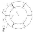
- the sheet metal segments 10 are arranged concentrically around a central axis M (see FIG. 2) and each have a predetermined one which influences the resistance to centrifugal forces minimum cross-sectional area A in the radial direction (see Fig. 1).
- the sheet metal segments 10 sheet metal layers 12 lying one above the other overlap one another in the circumferential direction in the example shown by about 25% and are along the circumferential surface distributed welding points 20 connected to each other.
- the connecting joints 14 of the sheet metal segments 10 are straight and oriented essentially radially.
- the radially oriented connecting joints 14 of the sheet metal segments 10 by teeth 14a, 14b can be hooked together, which also increases the stability of the assembly.
- the welding points 20 are on the inner peripheral surface the sheet metal segments 10 are arranged and are produced by means of laser welding.
- the length of the welding points can be seen in this example so short in relation to the inner segment length or the outer segment length that at the selected degree of overlap (i.e. the amount by which a sheet metal segment of a Layer covers a sheet metal segment of the next (or the previous) layer) Weld spots must be attached to both the inner circumference and the outer circumference can.
- the individual Weld spots are essentially circular and do not overlap.
- the welding spots overlap. In this case the effective area of the sum of the welding spots depending on the degree of coverage.
- the welding spots 20 are only shown at a few locations.
Landscapes
- Engineering & Computer Science (AREA)
- Power Engineering (AREA)
- Iron Core Of Rotating Electric Machines (AREA)
- Manufacture Of Motors, Generators (AREA)
Applications Claiming Priority (3)
| Application Number | Priority Date | Filing Date | Title |
|---|---|---|---|
| DE10110466 | 2001-03-05 | ||
| DE10110466A DE10110466A1 (de) | 2001-03-05 | 2001-03-05 | Baugruppe einer elektrischen Maschine und elektrische Maschine mit einer derartigen Baugruppe |
| PCT/EP2002/002407 WO2002071581A1 (de) | 2001-03-05 | 2002-03-05 | Baugruppe einer elektrischen maschine und elektrische maschine mit einer derartigen baugruppe |
Publications (2)
| Publication Number | Publication Date |
|---|---|
| EP1368883A1 EP1368883A1 (de) | 2003-12-10 |
| EP1368883B1 true EP1368883B1 (de) | 2004-07-28 |
Family
ID=7676318
Family Applications (1)
| Application Number | Title | Priority Date | Filing Date |
|---|---|---|---|
| EP02704732A Expired - Lifetime EP1368883B1 (de) | 2001-03-05 | 2002-03-05 | Baugruppe einer elektrischen maschine und elektrische maschine mit einer derartigen baugruppe |
Country Status (7)
Families Citing this family (14)
| Publication number | Priority date | Publication date | Assignee | Title |
|---|---|---|---|---|
| DE10036141B4 (de) | 2000-07-25 | 2005-09-08 | Siemens Ag | Verfahren zur verbesserten Auswahl eines Kommunikationsnetzes für eine Station |
| DE102006055264A1 (de) * | 2006-11-23 | 2008-05-29 | Robert Bosch Gmbh | Lamellenblechpaket für eine elektrische Vorrichtung, insbesondere für eine elektrische Maschine, und Verfahren zu dessen Herstellung |
| US20100066201A1 (en) * | 2008-09-16 | 2010-03-18 | Saia-Burgess Murten Ag | Electric motor |
| JP5659541B2 (ja) * | 2010-04-07 | 2015-01-28 | 株式会社デンソー | 回転電機のステータコア |
| US9099897B2 (en) | 2011-09-13 | 2015-08-04 | L.H. Carbide Corporation | Method for connecting end sections of an annular laminated article and articles made therefrom |
| DE102011055337A1 (de) * | 2011-11-15 | 2013-05-16 | Valeo Systèmes d'Essuyage | Scheibenwischermotor |
| WO2014023991A1 (es) * | 2012-08-09 | 2014-02-13 | Romero-Beltran Julian | Motor |
| DE102014200947A1 (de) * | 2014-01-20 | 2015-08-06 | Wobben Properties Gmbh | Synchrongenerator einer getriebelosen Windenergieanlage |
| DE102016108712A1 (de) | 2016-05-11 | 2017-11-16 | Wobben Properties Gmbh | Synchrongenerator einer getriebelosen Windenergieanlage sowie Verfahren zum Herstellen eines Synchrongenerators und Verwendung von Formspulen |
| FR3051990B1 (fr) * | 2016-05-27 | 2020-10-09 | Valeo Systemes De Controle Moteur | Machine electrique |
| US11025104B2 (en) * | 2018-02-09 | 2021-06-01 | General Electric Company | Electric machine |
| WO2021064450A1 (en) * | 2019-10-02 | 2021-04-08 | Dema S.R.L. | Device for manufacturing armatures of electric machines, especially stators and/or rotors, and manufacturing process |
| DE102023133405A1 (de) * | 2023-11-29 | 2025-06-05 | Vacuumschmelze Gmbh & Co. Kg | Blechpaket und Verfahren zum Herstellen eines Blechpakets |
| DE102024104034A1 (de) * | 2024-02-14 | 2025-08-14 | Schaeffler Technologies AG & Co. KG | Kreisringabschnittsförmiges, aus einem Elektroblech geformtes Rotorsegment, Blechpaketanordnung, segmentierter Rotor und elektrische Maschine |
Family Cites Families (13)
| Publication number | Priority date | Publication date | Assignee | Title |
|---|---|---|---|---|
| DE974711C (de) * | 1950-06-02 | 1961-04-06 | Siemens Ag | Aus einzelnen Blechsegmenten aufgebauter Jochring fuer den umlaufenden Erregerteil grosser Generatoren |
| DE1140638B (de) * | 1961-12-15 | 1962-12-06 | Licentia Gmbh | Aus einzelnen Blechsegmenten geschichteter Laeufer elektrischer Grossmaschinen |
| US3488754A (en) * | 1968-12-10 | 1970-01-06 | Allis Chalmers Mfg Co | Dynamoelectric machine rim construction with offset ring segments |
| US4114019A (en) * | 1976-12-22 | 1978-09-12 | Electric Machinery Mfg. Company | Welding of laminations of core-plated silicon steel |
| DE3027987C2 (de) | 1980-07-24 | 1984-08-16 | Maschinenfabrik Müller-Weingarten AG, 7987 Weingarten | Arbeitsverfahren und Einrichtung zum Paketieren von in Kreisringsegmente zerlegten Dynamoblechen |
| FR2631755A1 (fr) * | 1988-03-02 | 1989-11-24 | Emiliane Trancerie Spa | Procede pour la realisation d'un circuit magnetique de stator de machines electriques rotatives ou d'un circuit magnetique de transformateurs, et circuit magnetique ainsi obtenu |
| FR2673052B1 (fr) * | 1991-02-19 | 1995-06-23 | Jeumont Schneider Ind | Lits pour anneaux feuilletes ou toles. |
| JP3355700B2 (ja) | 1993-06-14 | 2002-12-09 | 松下電器産業株式会社 | 回転電機の固定子 |
| JPH09163691A (ja) * | 1995-12-01 | 1997-06-20 | Toshiba Mec Kk | 積層形コア及びその製造方法 |
| SE510422C2 (sv) * | 1996-11-04 | 1999-05-25 | Asea Brown Boveri | Magnetplåtkärna för elektriska maskiner |
| JP2000278892A (ja) * | 1999-03-19 | 2000-10-06 | Mitsubishi Electric Corp | 車両用交流発電機の固定子コア及び車両用交流発電機の固定子コアの製造方法 |
| DE10028097A1 (de) * | 1999-06-08 | 2001-02-01 | Fuerstlich Hohenzollernsche We | Läufer |
| US6448686B1 (en) * | 2000-12-08 | 2002-09-10 | General Electric Company | Packaged stator core and method forming the same |
-
2001
- 2001-03-05 DE DE10110466A patent/DE10110466A1/de not_active Ceased
-
2002
- 2002-03-05 US US10/469,886 patent/US6930428B2/en not_active Expired - Fee Related
- 2002-03-05 JP JP2002570381A patent/JP2004530397A/ja active Pending
- 2002-03-05 WO PCT/EP2002/002407 patent/WO2002071581A1/de active IP Right Grant
- 2002-03-05 ES ES02704732T patent/ES2224050T3/es not_active Expired - Lifetime
- 2002-03-05 DE DE50200709T patent/DE50200709D1/de not_active Expired - Lifetime
- 2002-03-05 KR KR10-2003-7011614A patent/KR20030081495A/ko not_active Withdrawn
- 2002-03-05 EP EP02704732A patent/EP1368883B1/de not_active Expired - Lifetime
Also Published As
| Publication number | Publication date |
|---|---|
| EP1368883A1 (de) | 2003-12-10 |
| ES2224050T3 (es) | 2005-03-01 |
| KR20030081495A (ko) | 2003-10-17 |
| DE10110466A1 (de) | 2002-09-26 |
| US20040130219A1 (en) | 2004-07-08 |
| DE50200709D1 (de) | 2004-09-02 |
| WO2002071581A1 (de) | 2002-09-12 |
| US6930428B2 (en) | 2005-08-16 |
| JP2004530397A (ja) | 2004-09-30 |
Similar Documents
| Publication | Publication Date | Title |
|---|---|---|
| DE69405465T2 (de) | Ständer einer dynamoelektrischen Maschine | |
| EP1368883B1 (de) | Baugruppe einer elektrischen maschine und elektrische maschine mit einer derartigen baugruppe | |
| EP2619883B1 (de) | Maschinenkomponente für eine elektrische maschine | |
| EP2327136B1 (de) | Permanentmagnet-synchronmotor und elektrische servolenkung | |
| EP1629590B1 (de) | Transversalflussmaschine | |
| WO1999010962A1 (de) | Elektrische maschine, deren rotor aus dauermagneten und magnetfluss-leitstücken aufgebaut ist | |
| DE112015001725T5 (de) | Drehende elektrische Maschine mit eingebetteten Permanentmagneten | |
| EP1811630A1 (de) | Rotierende elektrische Maschine | |
| EP1988620B1 (de) | Reluktanzmotor | |
| DE3907860A1 (de) | Laeufer fuer rotierende elektrische maschinen | |
| EP4070436B1 (de) | Axialflussmaschine mit radial verlaufende blechsegmente aufweisendem stator | |
| WO2017198406A1 (de) | Rotor einer elektrischen maschine mit einem blechpaket | |
| WO2017121511A1 (de) | Elektroblech mit gedrucktem steg | |
| EP0236690A2 (de) | Elektrische rotierende Maschine | |
| DE19704769C2 (de) | Mehrsträngige Synchronmaschine mit Permanentmagneten und Spulenmodulen | |
| DE10037804A1 (de) | Blechlamellen für Blechpakete für Rotoren und/oder Statoren für Generatoren, Motoren, Startergeneratoren, Generatorstarter und dergleichen sowie Verfahren zur Herstellung von solchen Blechlamellen | |
| DE102011054046A1 (de) | Spulendistanzblock einer dynamoelektrischen Maschine mit einer Strömungsablenkstruktur auf seiner spulenseitigen Oberfläche | |
| WO2017012765A1 (de) | Permanent erregte elektrische maschine mit optimierter geometrie | |
| DE102005036041B4 (de) | Permanenterregte elektrische Maschine | |
| DE102019122239A1 (de) | Stator | |
| EP3813237B1 (de) | Spulenmodul für eine elektrische maschine | |
| DE4443999C1 (de) | Permanenterregte Transversalflußmaschine mit einfachem Rotor | |
| DE2741036A1 (de) | Staffellaeufer fuer eine asynchronmaschine | |
| WO2021151413A1 (de) | Rotor für eine axialflussmaschine, verfahren zur herstellung eines rotors für eine axialflussmaschine und axialflussmaschine | |
| DE29715400U1 (de) | Elektrische Maschine, deren Rotor aus Dauermagneten und Magnetfluß-Leitstücken aufgebaut ist |
Legal Events
| Date | Code | Title | Description |
|---|---|---|---|
| PUAI | Public reference made under article 153(3) epc to a published international application that has entered the european phase |
Free format text: ORIGINAL CODE: 0009012 |
|
| 17P | Request for examination filed |
Effective date: 20030828 |
|
| AK | Designated contracting states |
Kind code of ref document: A1 Designated state(s): AT BE CH CY DE DK ES FI FR GB GR IE IT LI LU MC NL PT SE TR |
|
| AX | Request for extension of the european patent |
Extension state: AL LT LV MK RO SI |
|
| GRAP | Despatch of communication of intention to grant a patent |
Free format text: ORIGINAL CODE: EPIDOSNIGR1 |
|
| GRAS | Grant fee paid |
Free format text: ORIGINAL CODE: EPIDOSNIGR3 |
|
| GRAA | (expected) grant |
Free format text: ORIGINAL CODE: 0009210 |
|
| AK | Designated contracting states |
Kind code of ref document: B1 Designated state(s): DE ES FR GB IT SE |
|
| REG | Reference to a national code |
Ref country code: GB Ref legal event code: FG4D Free format text: NOT ENGLISH |
|
| REG | Reference to a national code |
Ref country code: SE Ref legal event code: TRGR |
|
| REG | Reference to a national code |
Ref country code: IE Ref legal event code: FG4D Free format text: GERMAN |
|
| REF | Corresponds to: |
Ref document number: 50200709 Country of ref document: DE Date of ref document: 20040902 Kind code of ref document: P |
|
| GBT | Gb: translation of ep patent filed (gb section 77(6)(a)/1977) |
Effective date: 20040909 |
|
| LTIE | Lt: invalidation of european patent or patent extension |
Effective date: 20040728 |
|
| PGFP | Annual fee paid to national office [announced via postgrant information from national office to epo] |
Ref country code: SE Payment date: 20050128 Year of fee payment: 4 |
|
| REG | Reference to a national code |
Ref country code: ES Ref legal event code: FG2A Ref document number: 2224050 Country of ref document: ES Kind code of ref document: T3 |
|
| PGFP | Annual fee paid to national office [announced via postgrant information from national office to epo] |
Ref country code: ES Payment date: 20050323 Year of fee payment: 4 |
|
| REG | Reference to a national code |
Ref country code: IE Ref legal event code: FD4D |
|
| PLBE | No opposition filed within time limit |
Free format text: ORIGINAL CODE: 0009261 |
|
| STAA | Information on the status of an ep patent application or granted ep patent |
Free format text: STATUS: NO OPPOSITION FILED WITHIN TIME LIMIT |
|
| ET | Fr: translation filed | ||
| 26N | No opposition filed |
Effective date: 20050429 |
|
| PG25 | Lapsed in a contracting state [announced via postgrant information from national office to epo] |
Ref country code: GB Free format text: LAPSE BECAUSE OF NON-PAYMENT OF DUE FEES Effective date: 20060305 |
|
| PG25 | Lapsed in a contracting state [announced via postgrant information from national office to epo] |
Ref country code: SE Free format text: LAPSE BECAUSE OF NON-PAYMENT OF DUE FEES Effective date: 20060306 Ref country code: ES Free format text: LAPSE BECAUSE OF NON-PAYMENT OF DUE FEES Effective date: 20060306 |
|
| PGFP | Annual fee paid to national office [announced via postgrant information from national office to epo] |
Ref country code: IT Payment date: 20060331 Year of fee payment: 5 |
|
| EUG | Se: european patent has lapsed | ||
| GBPC | Gb: european patent ceased through non-payment of renewal fee |
Effective date: 20060305 |
|
| REG | Reference to a national code |
Ref country code: ES Ref legal event code: FD2A Effective date: 20060306 |
|
| PG25 | Lapsed in a contracting state [announced via postgrant information from national office to epo] |
Ref country code: IT Free format text: LAPSE BECAUSE OF NON-PAYMENT OF DUE FEES Effective date: 20070305 |
|
| PGFP | Annual fee paid to national office [announced via postgrant information from national office to epo] |
Ref country code: DE Payment date: 20120328 Year of fee payment: 11 |
|
| PGFP | Annual fee paid to national office [announced via postgrant information from national office to epo] |
Ref country code: FR Payment date: 20120417 Year of fee payment: 11 |
|
| REG | Reference to a national code |
Ref country code: FR Ref legal event code: ST Effective date: 20131129 |
|
| REG | Reference to a national code |
Ref country code: DE Ref legal event code: R119 Ref document number: 50200709 Country of ref document: DE Effective date: 20131001 |
|
| PG25 | Lapsed in a contracting state [announced via postgrant information from national office to epo] |
Ref country code: DE Free format text: LAPSE BECAUSE OF NON-PAYMENT OF DUE FEES Effective date: 20131001 Ref country code: FR Free format text: LAPSE BECAUSE OF NON-PAYMENT OF DUE FEES Effective date: 20130402 |