EP1368086B1 - Support de fil-guide de catheter vasculaire - Google Patents
Support de fil-guide de catheter vasculaire Download PDFInfo
- Publication number
- EP1368086B1 EP1368086B1 EP02714365A EP02714365A EP1368086B1 EP 1368086 B1 EP1368086 B1 EP 1368086B1 EP 02714365 A EP02714365 A EP 02714365A EP 02714365 A EP02714365 A EP 02714365A EP 1368086 B1 EP1368086 B1 EP 1368086B1
- Authority
- EP
- European Patent Office
- Prior art keywords
- lumen
- catheter
- lumens
- opening
- distal
- Prior art date
- Legal status (The legal status is an assumption and is not a legal conclusion. Google has not performed a legal analysis and makes no representation as to the accuracy of the status listed.)
- Expired - Lifetime
Links
Images

Classifications
-
- A—HUMAN NECESSITIES
- A61—MEDICAL OR VETERINARY SCIENCE; HYGIENE
- A61M—DEVICES FOR INTRODUCING MEDIA INTO, OR ONTO, THE BODY; DEVICES FOR TRANSDUCING BODY MEDIA OR FOR TAKING MEDIA FROM THE BODY; DEVICES FOR PRODUCING OR ENDING SLEEP OR STUPOR
- A61M25/00—Catheters; Hollow probes
- A61M25/01—Introducing, guiding, advancing, emplacing or holding catheters
- A61M25/0172—Exchanging a guidewire while keeping the catheter in place
-
- A—HUMAN NECESSITIES
- A61—MEDICAL OR VETERINARY SCIENCE; HYGIENE
- A61M—DEVICES FOR INTRODUCING MEDIA INTO, OR ONTO, THE BODY; DEVICES FOR TRANSDUCING BODY MEDIA OR FOR TAKING MEDIA FROM THE BODY; DEVICES FOR PRODUCING OR ENDING SLEEP OR STUPOR
- A61M25/00—Catheters; Hollow probes
- A61M25/01—Introducing, guiding, advancing, emplacing or holding catheters
- A61M25/09—Guide wires
- A61M25/09041—Mechanisms for insertion of guide wires
-
- A—HUMAN NECESSITIES
- A61—MEDICAL OR VETERINARY SCIENCE; HYGIENE
- A61M—DEVICES FOR INTRODUCING MEDIA INTO, OR ONTO, THE BODY; DEVICES FOR TRANSDUCING BODY MEDIA OR FOR TAKING MEDIA FROM THE BODY; DEVICES FOR PRODUCING OR ENDING SLEEP OR STUPOR
- A61M25/00—Catheters; Hollow probes
- A61M25/0021—Catheters; Hollow probes characterised by the form of the tubing
- A61M25/0023—Catheters; Hollow probes characterised by the form of the tubing by the form of the lumen, e.g. cross-section, variable diameter
- A61M25/0026—Multi-lumen catheters with stationary elements
- A61M2025/004—Multi-lumen catheters with stationary elements characterized by lumina being arranged circumferentially
-
- A—HUMAN NECESSITIES
- A61—MEDICAL OR VETERINARY SCIENCE; HYGIENE
- A61M—DEVICES FOR INTRODUCING MEDIA INTO, OR ONTO, THE BODY; DEVICES FOR TRANSDUCING BODY MEDIA OR FOR TAKING MEDIA FROM THE BODY; DEVICES FOR PRODUCING OR ENDING SLEEP OR STUPOR
- A61M25/00—Catheters; Hollow probes
- A61M25/01—Introducing, guiding, advancing, emplacing or holding catheters
- A61M2025/0183—Rapid exchange or monorail catheters
-
- A—HUMAN NECESSITIES
- A61—MEDICAL OR VETERINARY SCIENCE; HYGIENE
- A61M—DEVICES FOR INTRODUCING MEDIA INTO, OR ONTO, THE BODY; DEVICES FOR TRANSDUCING BODY MEDIA OR FOR TAKING MEDIA FROM THE BODY; DEVICES FOR PRODUCING OR ENDING SLEEP OR STUPOR
- A61M25/00—Catheters; Hollow probes
- A61M25/10—Balloon catheters
- A61M2025/1043—Balloon catheters with special features or adapted for special applications
- A61M2025/1045—Balloon catheters with special features or adapted for special applications for treating bifurcations, e.g. balloons in y-configuration, separate balloons or special features of the catheter for treating bifurcations
Definitions
- the invention relates generally to intravenous catheters and, more specifically, an intravascular carrier catheter for introducing intravascular catheter guidewires to support subsequent introduction or replacement of other intravenous or intra-arterial catheters or interventional devices within the coronary and peripheral vasculature, particularly in the areas of bifurcated vessels or occluded vessels.
- US-A-5 908 446 discloses a catheter of this type.
- a guidewire is used to support advancement of the device in the vessel and positioned in the desired location under fluoroscopy.
- a catheter is introduced over the guidewire and appropriately positioned- In the clinical situation in which the patient has an occluded artery, for example, a relatively stiff guidewire is required to cross the occlusion and provide sufficient rigidity and support to the catheter.
- a balloon catheter may be introduced over the guidewire and the balloon inflated to open the lesion and/or to place a stent at the site of the lesion.
- the procedure is repeated with separate catheters and guidewires inserted into branches of the bifurcation, necessitating the introduction of multiple catheters and guidewires.
- interventional devices such as pressure sensing leads or the like, or desires to introduce drugs to the site
- more than one guidewire must be inserted and left in place so that another catheter or device can be employed. It has been known that when multiple guidewires are employed, for whatever the reason, the guidewires can become crossed or entangled within a vessel.
- the interventional device for example a pressure sensing lead, is thin and does not have the rigidity to allow the operator to pass the device through a narrowed vessel or occlusion.
- the present invention is employed as an apparatus for introducing, removing or changing one or more intravascular guidewires without crossing or entanglement of the guidewires.
- Another aspect of the invention is to provide an apparatus for the introduction and positioning multiple guidewires to allow for the subsequent introduction and proper placement of interventional devices over the guidewires.
- a further aspect of the invention is an apparatus for carrying deploying in the vasculature interventional devices that ordinarily cannot be introduced across, or are difficult to introduce across, vascular occlusions.
- Another aspect of the invention provides an apparatus that is particularly adaptable for use in the presence of lesions in bifurcated vascular areas.
- the invention according to the independent claims is an intravascular carrier catheter provided for the introduction and positioning of multiple guidewires or other devices, in a single step, generally beyond an occlusive lesion or at a bifurcation.
- the carrier catheter of the present invention includes an elongated, thin flexible catheter body.
- the catheter body includes a primary or lead lumen and, in the preferred embodiment, two additional or ancillary lumens.
- the invention includes a primary lumen and more or less than two ancillary lumens.
- the primary lumen has an opening at the proximal end and an opening at the distal end so that a lead guidewire can extend through the length of the lumen.
- the ancillary lumens are designed to accommodate additional guidewires or to seat interventional devices, such as sensing leads, for deployment within the vasculature.
- the openings at the distal ends of the lumens are positioned offset relative to each other so as to have the respective guidewires or devices exit the lumens at different points along the distal length of the catheter.
- the catheter includes an introductory apparatus that can be a semi-rigid push wire, or a semi rigid extension of the catheter body, at the proximal end and a shorter catheter body at the distal end of the push wire.
- the catheter body is of conventional length and may include hardware, such as Luer-lok® type connection, at the proximal ends of each lumen.
- the opening of the primary guidewire lumen generally is positioned at the extreme distal end of the catheter with the distal openings of the second and third ancillary lumens arranged up the length of the catheter from that opening.
- guidewires are positioned within the second and third lumens.
- Other interventional devices can be employed in the ancillary lumens.
- the primary lumen is placed over the proximal end of previously positioned dedicated guidewire and the catheter is introduced into the vessel or any other biological conduit over the dedicated guidewire and thus, appropriately positioned.
- the second and third guidewires or devices are positioned within their respective ancillary lumens so as to not protrude from the distal openings of those lumens.
- the catheter includes radio-opaque markers or markings to guide placement under fluoroscopy.
- the carrier catheter can be withdrawn and the guidewires or devices left in place. If guidewires are initially employed in the ancillary lumens and then left in place, other interventional devices can be introduced over any one of the appropriately placed guidewires.
- the device of the present invention can be employed to facilitate the changing of an indwelling catheter.
- the indwelling catheter is withdrawn over the appropriate guide wire.
- the guidewire remains in place and the replacement catheter is advanced along the guidewire.
- one catheter can be used to position three guidewires and those three guidewires can be used to introduce three separate catheters or interventional devices into the vessel.
- the device of the present invention can be employed to facilitate the changing of a dedicated guidewire.
- the primary lumen of the catheter of the present invention is introduced over the subject guidewire and positioned.
- the replacement guidewire is introduced through one of the ancillary lumens, which is adjacent to the lumen containing the subject guidewire.
- the subject guidewire is withdrawn and the catheter can be withdrawn over the new guidewire, leaving in place the new guidewire, which was introduced through the ancillary lumen and positioned where the extracted guidewire had resided. It will be appreciated that since the device of the present invention includes multiple lumens, more than one guidewire can be replaced with one catheter introduction.
- the invention is a versatile, multi-lumen carrier catheter that can be used for the introduction and placement of multiple guidewires or for the introduction and placement of interventional devices, including devices that can be introduced over a guidewire and devices that cannot be introduced over a guidewire.
- the carrier catheter also is used to replace an indwelling catheter or to change dedicated guidewires.
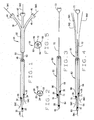
- One preferred embodiment of the novel carrier catheter of the present invention is indicated by reference numeral 20 in Fig. 1.
- Catheter 20 includes an elongated, generally flexible body section 22 formed from biologically compatible materials known to the art. Generally, flexible implies that the catheter is not so rigid as to increase the risk of puncture or dissection of a vessel when inserted but appropriately inflexible so as to allow it to be inserted into a vessel with a guidewire.
- the body section of catheter 20 includes three inner bores or lumens 24, 26 and 28.
- the three lumens are contained within the body section 22 so that the cross-section of the body section is circular.
- Body 22 can be solid with the lumens formed therein or the lumens can be discrete elongated tubes or passageways contained within a covering to form the body. Any other construction that provides for a catheter body having three separate lumens or bores is acceptable. When the body is described or claimed as having one or more lumens, any configuration or construction of lumens is intended.
- the first or primary lumen 24 terminates distally in port or opening 30.
- This lumen also can be referred to as the lead or drive lumen in that, generally, the lead or introductory guidewire is employed in this lumen
- the second lumen 26 terminates distally in a port or opening 32 and the third lumen 28 terminates distally in port or opening 34.
- the second and third lumens can be referred to as ancillary lumens. They also can be referred to as cargo or loading lumens to reflect the fact that they can be used to carrier and deploy interventional devices other than guidewires, as will be described below.
- the distal opening 30 of the primary lumen is the distal most opening, while openings 32 and 34 are positioned up from opening 30. That is, the second and third openings 32, 34, respectively, are positioned in a proximal relationship to opening 30. It will be appreciated that openings 32, 34 can be placed at any desired location along the length of body 22, as required by the application of the catheter. For example, in the illustrated embodiment, opening 34 also is proximal to opening 32.
- the body 22 can be preformed with openings 32 and 34 in the lumens located at desired locations or, if necessary, the body and lumens can be cut on the spot to create openings 32 and 34 at desired relative locations based upon a clinical evaluation of the intended use.
- the lumens preferably include radio-opaque marks 35 adjacent the openings to allow appropriate positioning of openings 30, 32 and 34 under fluoroscopy. Any placement of radio-opaque markers or other appropriate markers along the length of the catheter that facilitate proper placement of the catheter is contemplated by the invention.
- the relative positions of openings 30, 32 and 34 can be arranged to optimize the use of catheter 20 in bifurcated arteries.
- the proximal ends of lumens 24, 26 and 28 terminate in extensions 36, 38 and 40, respectively.
- the extensions are integral and the terminal ends of the extensions are equipped with Luer-lok®-type connectors 42, 44 and 46, respectively.
- Luer-lok®-type connectors 42, 44 and 46 are used to attach the catheter to devices, such as syringes or the like, to facilitate introduction or placement of the catheter in a vessel or for the introduction of a pharmaceutical, such as a thrombolytic agent or any other pharmaceutical agent, through the catheter lumens.
- a first or lead guidewire GW1 extends through lumen 24
- a second guidewire GW2 extends through lumen 26
- a third guidewire GW3 extends through lumen 28.
- the standard guidewires are approximately 0,3556 mm (0,014 inch) in diameter.
- GW1 as the lead guidewire, can have a diameter greater than the standard or more stiffness so that can endure greater torque to facilitate passage of the catheter through the vasculature and across an occlusive lesion.
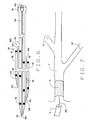
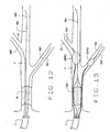
- Figs. 3, 4 and 5 illustrate another embodiment of the catheter of the present invention, indicated generally by numeral 60.
- Catheter 60 includes an elongated catheter body 62, which is relatively shorter than catheter body 22.
- catheter body 62 is constructed similarly to the catheter body 22.
- the body 62 includes inner lumens 64, 66 and 68 (Fig. 5) which terminate distally in ports or openings 69, 70 and 71, respectively.
- catheter 60 includes an introductory apparatus which can be a substantially inflexible proximal extension of the catheter body or, as shown in the illustrated embodiment, an integral push wire 72 which can include a connector or other fitting 73 at its proximal end.
- Push wire 72 which is formed from steel or other appropriate material, is sufficiently rigid to allow the introduction of the catheter body into position within a vein or artery when advancing down a lead guidewire positioned in lumen 64. Push wire 72 is not so inflexible so as to cause an undue risk of dissection during use.
- the catheter also includes external radio opaque marks 35 adjacent the openings 69, 70 and 71, as previously explained. As seen in Fig. 4, guidewires GW1, GW2 and GW3 extend through the lumens 64, 66 and 68 respectively.
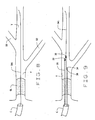
- Fig. 6 illustrates in cross-section of yet another exemplary embodiment of the catheter of the present invention, indicated generally by numeral 80.
- Catheter 80 includes a main body section 82, having a primary central bore or lumen 84. There is an opening 86 of lumen 84 at the distal end of body section 82. The proximal end of body section 82 terminates in a Luer-lok® -type connection 88. The overall length of catheter 80, from the distal opening 86 to connection 88 is approximately 115 cm to approximately 135 cm.
- the distal openings 86, 94 and 102 are juxtaposed in any desired relationship so the openings to the lumens are located along the distal length of catheter 80 in desired locations.
- proximal openings 96 and 104 are positioned as desired.
- second ancillary body section 98 is positioned proximally relative to the first ancillary body section. In this embodiment it is approximately 25 cm to approximately 35 cm from distal opening 86 to proximal opening 104. There are radio-opaque marks 35 adjacent the various distal and proximal openings to allow for appropriate positioning under fluoroscopy. It will be appreciated that the longitudinally contiguous portions of three body sections can have a common covering, if desired. As shown, main body section is substantially longer than the two ancillary sections. For example, a representative catheter 80 may have an overall length of 115 to 135 cm, while the length of the ancillary sections would be approximately 25 to 35 cm.
- each of the recited bores accommodates a guidewires GW1, GW2 and GW3.
- the design can be altered to include ancillary lumens of different lengths.
- the ancillary body sections can be elastic so that lumens 96 and 104 can expand to accommodate wires or devices having a greater diameter that a standard guidewire, which, generally is about 0,3556 mm (0.014 inch.)
- lumens 96 and 104 can be tapered from a greater diameter at the proximal end to a smaller diameter at the distal end in order to facilitate introduction of interventional devices into the lumens.
- the exemplary embodiments disclose carrier catheters having three lumens, It is to be understood that the construction of the respective catheters can be modified to include fewer than three and, if the diameter of the target biological conduit is sufficiently large, the bodies of the respective carrier catheters can include more than three lumens, without departing from the scope of the present invention.
- the three illustrated exemplary embodiments of the catheter of the present invention, or modifications thereof having more or less than three lumens, can be used in similar clinical situations and each may offer some distinct advantage.
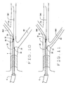
- the method of using the novel catheters is illustrated in Figs. 7-14.
- the catheters are intended to be used in biological conduits or lumens, such as arteries, veins, tubes, ducts, canals, other vessels and similar anatomical structures, in the body of a subject in need of such use.
- the term vessel is used herein to encompass all such anatomical structures.
- subject is intended to include any subject, regardless of species.
- One exemplary vessel is a coronary artery.
- One exemplary subject is a human subject. As seen in Fig.
- an occlusive lesion OL in vessel V is documented by acceptable clinical and diagnostic methods.
- a conventional guide catheter C of known construction is appropriately positioned at the vessel V.
- a first guidewire GW1 is advanced through the guide catheter C to the site. As seen in Fig. 8, the first guidewire GW1 is advanced, crossing lesion OL and positioned in the parent vessel V with the distal tip of the wire positioned distally to or beyond the lesion.
- the guide catheter C is left in place during the procedure to accommodate the injection of dye into the vessel during the procedure. If desired, after injecting the dye, the guide catheter can be withdrawn.
- the proximal end of the first guidewire GW1 is introduced into the first lumen through distal opening 30 of a novel catheter 20 (or opening 69 of catheter 60, or opening 86 of catheter 80).
- Second and third guidewires GW2 and GW3 are positioned within the second and third lumens, for example lumens 26 and 28, from the proximal end of the catheter.
- Catheter 20 is advanced by riding down the first guidewire GW1.
- the distal end of catheter 20 is positioned under fluoroscopy with the radio opaque marks 35 visualized to assure proper positioning of the lumen openings 32 and 34.
- opening 32 is positioned so that second guidewire GW2 can be advanced into a first side branch B1 of the vessel.
- opening 34 is positioned so that the third guidewire GW3 can be advanced into another side branch B2.
- the carrier catheter 20 can function as the guide catheter.
- the catheter 20 can be withdrawn and removed, leaving the three guidewires GW1, GW2 and GW3 in position for the introduction of other interventional apparatus as shown in Fig. 13 and Fig.14.
- Fig. 13 illustrates the placement of interventional devices and, in this illustration, the devices are commonly referred to as distal embolization protective devices (DEPDs), shown in the figure as DEPD-1 and DEPD-2. These devices are placed to avoid distal embolization caused by percutanous transluminal coronary angioplasty (PTCA) with a PTCA balloon AB1. Debris is blocked by the inflated DEPD balloon and then aspirated through a catheter.
- DEPDs distal embolization protective devices
- DEPDs examples include Percusurge® (Purcusurge, Inc., Sunnyvale, California, Guardwire Plus tm Temporary Occlusion Catheter (Medtronic, Inc., Minneapolis, MN), and FilterWire Ex tm (Boston Scientific EPI, Santa Clara, CA). These devices also can function as a common guidewire for the advancement and placement. Each of these representative devices has specific uses and any DEPD disclosed or not disclosed herein is intended for use with the carrier catheter of the present invention.
- Fig. 14 represents one exemplary form of interventional apparatus as percutanous transluminal coronary angioplasty (PTCA) balloons AB1, AB2 and AB3, which can be deployed by techniques known to the art over guidewires introduced and positioned using the carrier catheter of the present invention.
- Any other desired device such as balloons, stents, pressure sensing devices, drug delivery systems or the like may be introduced to the appropriate site by employing one of the three guidewires.
- the indwelling guidewires GW1, GW2 and GW3 function as dedicated guidewires for future use of catheter borne interventions.
- the term "dedicated guidewire" is intended to include any guidewire that is placed in a vessel and left for an appreciable amount of time for further use.
- the carrier catheter of the present invention can be used to deploy an interventional device that generally is introduced directly into the vasculature or a device that is difficult or impossible to use in the presence of an occlusion
- interventional devices are devoid of a drive or introductory guidewire lumen and, do to their flexibility, cannot be forced across a lesion.
- Such devices can include a simple fiber optic wire or a pressure or sensing leads such as flow monitoring leads or thermal leads.
- FloWire tm Doppler Guide Wire EndoSonics Corporation, Collinso Cordova, CA.
- the carrier catheter of the present invention positioned with the lead guidewire inside the primary or drive lumen.
- the lead guidewire can already be dedicated in the vasculature or can be introduced into the primary catheter lumen from the proximal end.
- the intervention device for example a pressure flow monitoring lead, is introduced into one of the ancillary lumens, and usually does not extend out of the opening at the distal end.
- the catheter is advanced down the lead guidewire until the opening of the ancillary lumen is positioned at a predetermined location within the vessel so that the flow monitoring lead is located at the desired location.
- the carrier catheter can be withdrawn over the guidewire and monitoring lead, leaving the monitoring lead in its predetermined desired location.
- the carrier employs the drive guidewire in the primary lumen allows the catheter to pass through any occluded area, carrying the very flexible lead across the lesion inside the ancillary lumen.
- a second interventional device or an ancillary guidewire can be deployed from a second ancillary lumen, if one is provided on the carrier catheter.
- other interventional devices or combination of guidewires or interventional devices that is desired or useful may be placed with the novel carrier catheter, even in the presence of an occlusion.
- three guidewires, or combinations of guidewires and interventional devices can be placed with only one catheter crossing of the lesion OL. This significantly reduces the procedure time and the risk of complications that can occur with multiple crossing of the lesion.
- each of the exemplary catheters can be used for a rapid exchange of an indwelling catheter into either the primary vessel, the first side branch or second side branch.
- the indwelling catheter is withdrawn over the appropriate guide wire.
- the guidewire remains in place and the replacement catheter is advanced along the guidewire.
- one catheter can be used to position three guidewires and those three guidewires can be used to introduce three separate catheters into the vessels, if desired.
- a novel catheter of the present invention can have non-catheter borne devices or devices that heretofore unsuited for crossing an occlusive lesion loaded in the ancillary lumens. The catheter is deployed by riding down the primary guidewire so that the user can deploy these type devices in a desired location.
- the catheter of the present invention can be used for rapid exchange of a dedicated guidewire. If the physician desires to exchange dedicated guidewire GW1, for example, he can place lumen 24 of a catheter 20 over guidewire GW1 and can introduce a replacement guidewire into adjacent lumen 26. He can advance the catheter along GW1 until opening 32 of lumen 26 is distal to or beyond the branches B1 and B2, if that is the structure of the vessel. In any event, he advances the catheter 20 until opening 32 of lumen 26 is adjacent the distal end of GW so that the distal end of the replacement guidewire is positioned approximately where the distal end of GW1 is positioned. He then can withdraw old guidewire GW1 through the proximal end of lumen 24. Subsequently, he can withdraw the catheter over the replacement guidewire leaving the replacement guidewire in the parent vessel in the approximate location of the removed guidewire.
- the practitioner can replace a dedicated guidewire with only one maneuver, avoiding the risks associated with multiple crossings of a lesion with guidewires.
- catheter 20, 60 or 80 can be used in the above procedures.
- catheter 60, Figs. 3-5 is particularly well adapted to the rapid changing of dedicated or indwelling guidewires and catheters.
- the novel carrier catheter of the present invention exhibits exceptional versatility, safety and ease of use.
- the device can be employed to deploy the devices previously described and the guidewires can be employed for the deployment of other, non-catheter borne devices such as fiber optic wires, pressure or flow measurement leads or the like, particularly to a site beyond an occlusion.
- the catheter of the present invention is illustrated having three (3) lumens to accommodate three (3) guidewires, the catheter of the present invention can be constructed to have two lumens or more than three lumens. A catheter with any number of lumens is intended by encompassed by the claims to the instant invention.
Claims (20)
- Cathéter porteur (80) à utiliser dans un vaisseau dans un conduit biologique dans le corps d'un sujet, comprenant : un corps allongé (82, 90, 98) comprenant une première lumière (84) formée longitudinalement à l'intérieur, ladite première lumière ayant une ouverture à l'intérieur au niveau d'une extrémité proximale et une ouverture (86) à l'intérieur au niveau d'une extrémité distale, ledit corps ayant au moins une deuxième lumière (92 ; 100) formée longitudinalement à l'intérieur, ladite deuxième lumière ayant une ouverture à l'intérieur au niveau d'une extrémité proximale et une ouverture (94 ; 102) à l'intérieur au niveau d'une extrémité distale, lesdites ouvertures énumérées dans les extrémités distales desdites lumières étant positionnées de sorte qu'un fil guide avancé à travers n'importe laquelle desdites lumières énumérées soit positionné au niveau d'un emplacement prédéterminé dans le vaisseau, caractérisé en ce que
ledit corps comprend une section de corps principale comprenant ladite première lumière (84) et au moins une section de corps auxiliaire ou une deuxième section de corps positionnée sur un côté de la section de corps principale comprenant ladite deuxième lumière (92 ; 100), ladite section de corps principale et ladite au moins deuxième section de corps sont contigues longitudinalement, dans lequel
ladite section de corps principale est sensiblement plus longue que ladite au moins deuxième section de corps afin de disposer lesdites ouvertures distales (86 ; 94 ; 102) des lumières de manière décalée les unes par rapport aux autres de manière à avoir les ouvertures distales (86 ; 94 ; 102) des lumières au niveau de points différents le long de la longueur distale du cathéter et de manière à avoir toutes lesdites ouvertures distales (86 ; 94 ; 102) des lumières (84, 92, 100) faisant face à la direction longitudinale du cathéter. - Cathéter porteur selon la revendication 1, dans lequel ledit corps (22 ; 62 ; 82, 90, 98) comprend en outre une troisième lumière (28; 68 ; 100) formée longitudinalement à l'intérieur, ladite troisième lumière ayant une ouverture à l'intérieur au niveau d'une extrémité proximale et une ouverture (34 ; 71 ; 102) à l'intérieur au niveau d'une extrémité distale.
- Cathéter porteur selon la revendication 2, dans lequel lesdites ouvertures dans lesdites extrémités proximales desdites première, deuxième et troisième lumières (24, 26, 28 ; 64, 66, 68 ; 84, 92, 100) sont alignées dans un même plan.
- Cathéter porteur selon la revendication 1, dans lequel chacune desdites extrémités proximales de chacune desdites lumières porte un raccord.
- Cathéter porteur selon la revendication 1, dans lequel ladite extrémité proximale de ladite première lumière (24 ; 64 ; 84) porte un raccord.
- Cathéter porteur selon la revendication 1, dans lequel ledit corps comprend en outre un appareil d'introduction.
- Cathéter porteur selon la revendication 6, dans lequel ledit appareil d'introduction est un fil à pousser (72).
- Cathéter porteur selon la revendication 6, dans lequel ledit appareil d'introduction comprend en outre un raccord sur une extrémité proximale.
- Cathéter porteur selon la revendication 2, dans lequel lesdites ouvertures (32, 34 ; 70, 71 ; 94, 100) dans les extrémités distales desdites deuxième et troisième lumières sont proximales par rapport à l'ouverture (30 ; 69 ; 86) dans l'extrémité distale de la première lumière.
- Cathéter porteur selon la revendication 9, dans lequel ladite ouverture (34 ; 71 ; 102) dans l'extrémité distale de ladite troisième lumière est proximale par rapport à l'ouverture (32 ; 70 ; 94) dans l'extrémité distale de la deuxième lumière.
- Cathéter porteur selon la revendication 1, comprenant en outre des marqueurs radio-opaques le long de la longueur du corps pour faciliter le placement du cathéter.
- Cathéter porteur (20) à utiliser lors du placement de fils guides ou de dispositifs d'intervention au niveau d'une position prédéterminée dans un vaisseau dans le corps d'un sujet, comprenant : un corps comprenant une première structure de lumière, ladite première structure de lumière ayant une ouverture à l'intérieur au niveau d'une extrémité proximale et une ouverture (30) à l'intérieur au niveau d'une extrémité distale, ledit corps ayant au moins une deuxième structure de lumière, ladite au moins deuxième structure de lumière ayant une ouverture à l'intérieur au niveau d'une extrémité proximale et une ouverture (32 ; 34) à l'intérieur au niveau d'une extrémité distale proximale par rapport à ladite ouverture dans ladite extrémité distale de ladite première lumière, lesdites ouvertures énumérées dans les extrémités distales desdites lumières étant positionnées de sorte qu'un fil guide ou un dispositif d'intervention avancé à travers n'importe laquelle desdites structures de lumière énumérées soit positionné au niveau de l'emplacement prédéterminé dans le vaisseau
dans lequel ladite première structure de lumière et ladite au moins deuxième structure de lumière sont contiguës longitudinalement,
caractérisé en ce que ladite première structure de lumière est sensiblement plus longue que ladite au moins deuxième structure de lumière afin de disposer lesdites ouvertures distales (30, 32 ; 34) des lumières de manière décalée les unes par rapport aux autres de manière à avoir les ouvertures distales (30, 32 ; 34) des lumières au niveau de points différents le long de la longueur distale du cathéter et de manière à avoir toutes lesdites ouvertures distales (30, 32 ; 34) des lumières faisant face à la direction longitudinale du cathéter. - Cathéter porteur selon la revendication 12, dans lequel ledit corps comprend une troisième structure de lumière, ladite troisième structure de lumière ayant une ouverture à l'intérieur au niveau d'une extrémité proximale et une ouverture (34) à l'intérieur au niveau d'une extrémité distale proximale par rapport à ladite ouverture dans ladite extrémité distale de ladite première structure de lumière.
- Cathéter porteur selon la revendication 12, dans lequel ladite première lumière et ladite au moins deuxième lumière sont effilées.
- Cathéter porteur selon la revendication 13, dans lequel ladite au moins deuxième lumière et ladite troisième lumière sont extensibles.
- Cathéter porteur selon la revendication 12, dans lequel ladite extrémité proximale de ladite première lumière comprend en outre un raccord.
- Cathéter porteur selon la revendication 13, dans lequel lesdites extrémités proximales desdites deuxième et troisième lumières comprennent en outre un raccord.
- Cathéter porteur selon la revendication 12, comprenant en outre un appareil d'introduction.
- Cathéter porteur selon la revendication 12, comprenant en outre une pluralité de marqueurs pour faciliter le positionnement desdites ouvertures énumérées dans les extrémités distales des lumières énumérées au niveau de l'emplacement prédéterminé dans le vaisseau.
- Kit destiné à distribuer et déployer au moins un fil guide ou un dispositif d'intervention dans un conduit dans le corps d'un sujet, comprenant : un cathéter porteur selon la revendication 1, et au moins un fil guide.
Applications Claiming Priority (3)
| Application Number | Priority Date | Filing Date | Title |
|---|---|---|---|
| US27583201P | 2001-03-14 | 2001-03-14 | |
| US275832P | 2001-03-14 | ||
| PCT/IB2002/000722 WO2002072186A2 (fr) | 2001-03-14 | 2002-03-12 | Support de fil-guide de catheter vasculaire |
Publications (2)
| Publication Number | Publication Date |
|---|---|
| EP1368086A2 EP1368086A2 (fr) | 2003-12-10 |
| EP1368086B1 true EP1368086B1 (fr) | 2007-12-19 |
Family
ID=23053977
Family Applications (1)
| Application Number | Title | Priority Date | Filing Date |
|---|---|---|---|
| EP02714365A Expired - Lifetime EP1368086B1 (fr) | 2001-03-14 | 2002-03-12 | Support de fil-guide de catheter vasculaire |
Country Status (8)
| Country | Link |
|---|---|
| US (1) | US7645273B2 (fr) |
| EP (1) | EP1368086B1 (fr) |
| JP (1) | JP2004535847A (fr) |
| AT (1) | ATE381365T1 (fr) |
| AU (1) | AU2002246279A1 (fr) |
| DE (1) | DE60224171T2 (fr) |
| ES (1) | ES2298357T3 (fr) |
| WO (1) | WO2002072186A2 (fr) |
Cited By (1)
| Publication number | Priority date | Publication date | Assignee | Title |
|---|---|---|---|---|
| US7645273B2 (en) | 2001-03-14 | 2010-01-12 | Evr Medical S.A.R.L. | Vascular catheter guide wire carrier |
Families Citing this family (61)
| Publication number | Priority date | Publication date | Assignee | Title |
|---|---|---|---|---|
| US8202315B2 (en) | 2001-04-24 | 2012-06-19 | Mitralign, Inc. | Catheter-based annuloplasty using ventricularly positioned catheter |
| US20050119735A1 (en) | 2002-10-21 | 2005-06-02 | Spence Paul A. | Tissue fastening systems and methods utilizing magnetic guidance |
| JP2006503651A (ja) | 2002-10-21 | 2006-02-02 | ミトラリグン・インコーポレーテッド | ひだ形成を使用したカテーテルベースの環状形成手術を実行するための方法および装置 |
| AU2003275052A1 (en) * | 2003-08-05 | 2005-03-07 | Flowmedica, Inc. | System and method for prevention of radiocontrast induced nephropathy |
| US7166127B2 (en) | 2003-12-23 | 2007-01-23 | Mitralign, Inc. | Tissue fastening systems and methods utilizing magnetic guidance |
| US8864822B2 (en) | 2003-12-23 | 2014-10-21 | Mitralign, Inc. | Devices and methods for introducing elements into tissue |
| WO2005094540A2 (fr) * | 2004-03-25 | 2005-10-13 | Hong Mun K | Dispositif permettant de faciliter la recanalisation des occlusions totales |
| JP4821947B2 (ja) * | 2004-10-19 | 2011-11-24 | 朝日インテック株式会社 | 薬液注入装置 |
| JP2006223338A (ja) * | 2005-02-15 | 2006-08-31 | Humed Co Ltd | カテーテル |
| US7722666B2 (en) * | 2005-04-15 | 2010-05-25 | Boston Scientific Scimed, Inc. | Valve apparatus, system and method |
| US20060259009A1 (en) * | 2005-05-12 | 2006-11-16 | Medtronic Vascular, Inc. | Guidewire loader for bifurcated vessel |
| NO327189B1 (no) | 2005-06-03 | 2009-05-04 | Urological As | Utstyr for å skifte kateter |
| US7901367B2 (en) * | 2005-06-30 | 2011-03-08 | Cook Incorporated | Wire guide advancement system |
| US8951285B2 (en) | 2005-07-05 | 2015-02-10 | Mitralign, Inc. | Tissue anchor, anchoring system and methods of using the same |
| JP4868387B2 (ja) * | 2005-09-21 | 2012-02-01 | 朝日インテック株式会社 | 薬液注入装置 |
| US20070250149A1 (en) * | 2006-04-21 | 2007-10-25 | Abbott Laboratories | Stiffening Support Catheters and Methods for Using the Same |
| US7993303B2 (en) | 2006-04-21 | 2011-08-09 | Abbott Laboratories | Stiffening support catheter and methods for using the same |
| US8206370B2 (en) * | 2006-04-21 | 2012-06-26 | Abbott Laboratories | Dual lumen guidewire support catheter |
| US8246574B2 (en) * | 2006-04-21 | 2012-08-21 | Abbott Laboratories | Support catheter |
| US7927305B2 (en) * | 2006-04-21 | 2011-04-19 | Abbott Laboratories | Systems, methods, and devices for injecting media contrast |
| US20080009804A1 (en) * | 2006-07-10 | 2008-01-10 | Cook Incoporated | Vascular catheter apparatus and method |
| WO2008051898A2 (fr) * | 2006-10-22 | 2008-05-02 | Via Biomedical, Inc. | Dispositifs et procédés pour dérouler ou empêcher l'enroulement de dispositifs médicaux allongés |
| ATE499964T1 (de) * | 2006-12-22 | 2011-03-15 | Wilson Cook Medical Inc | Trennbare drahtführung |
| US8911461B2 (en) | 2007-03-13 | 2014-12-16 | Mitralign, Inc. | Suture cutter and method of cutting suture |
| US20080228265A1 (en) | 2007-03-13 | 2008-09-18 | Mitralign, Inc. | Tissue anchors, systems and methods, and devices |
| US11660190B2 (en) | 2007-03-13 | 2023-05-30 | Edwards Lifesciences Corporation | Tissue anchors, systems and methods, and devices |
| US9126020B2 (en) | 2007-06-26 | 2015-09-08 | Roxwood Medical, Inc. | Catheter apparatus with telescoping lumen catheters and its use in methods for treating vasculatures |
| JP5758626B2 (ja) * | 2007-06-26 | 2015-08-05 | ロックスウッド・メディカル・インコーポレイテッド | 脈管構造を治療するためのカテーテル装置 |
| US9125683B2 (en) | 2007-06-26 | 2015-09-08 | Roxwood Medical Inc. | Method and apparatus for placing a catheter within a vasculature |
| US9358037B2 (en) | 2007-06-26 | 2016-06-07 | Roxwood Medical, Inc. | Method and apparatus for centering a microcatheter within a vasculature |
| WO2009026419A1 (fr) * | 2007-08-23 | 2009-02-26 | Saint-Gobain Abrasives, Inc. | Conception de conditionneur cmp optimisée pour cmp oxyde/métal de la future génération |
| US8382829B1 (en) | 2008-03-10 | 2013-02-26 | Mitralign, Inc. | Method to reduce mitral regurgitation by cinching the commissure of the mitral valve |
| KR100958886B1 (ko) * | 2008-03-27 | 2010-05-20 | 연세대학교 산학협력단 | 주혈관과 분지혈관에 설치된 스텐트의 위치이동 및 만성폐색병변 시술용 카테터 |
| AU2010337128B2 (en) * | 2009-12-14 | 2015-11-26 | Michael G. Tal | Intravascular catheter with positioning markers and method of placement |
| US8591450B2 (en) | 2010-06-07 | 2013-11-26 | Rex Medical L.P. | Dialysis catheter |
| US8961549B2 (en) | 2010-11-18 | 2015-02-24 | John Miller Conn | Retrograde entry antegrade placement for femoral artery access |
| US10335193B2 (en) | 2010-11-18 | 2019-07-02 | Polr Angioscience, Llc | Retrograde entry antegrade placement for femoral artery access |
| US20120239003A1 (en) * | 2011-03-15 | 2012-09-20 | Boston Scientific Scimed, Inc. | Multiple Guidewire System |
| US8728011B2 (en) | 2011-07-22 | 2014-05-20 | Michael D. Khoury | Multi wire sheath |
| DK2765944T3 (en) | 2011-10-14 | 2018-12-03 | Ra Medical Systems Inc | LITTLE FLEXIBLE CATHETS WITH LIQUID CORE FOR LASER ABLATION IN BODY SLUMPS |
| US20130304030A1 (en) * | 2011-11-05 | 2013-11-14 | Vadiswire Corp. | Medical guidewire system with plural parallel guidewires |
| JP6381536B2 (ja) | 2012-10-22 | 2018-08-29 | ロックスウッド メディカル, インコーポレイテッド | 血管系内でマイクロカテーテルを心合するための方法および装置 |
| GB2507761A (en) * | 2012-11-08 | 2014-05-14 | Barking Havering And Redbridge University Hospitals Nat Health Service Trust | A device for introducing a medical element into a blood vessel |
| US9272121B2 (en) | 2013-03-13 | 2016-03-01 | Invatec S.P.A. | Side lumen reentry catheters and related methods |
| US10213584B2 (en) | 2013-04-10 | 2019-02-26 | The Cleveland Clinic Foundation | Method and apparatus for guiding a catheter |
| US10070857B2 (en) | 2013-08-31 | 2018-09-11 | Mitralign, Inc. | Devices and methods for locating and implanting tissue anchors at mitral valve commissure |
| US9962527B2 (en) | 2013-10-16 | 2018-05-08 | Ra Medical Systems, Inc. | Methods and devices for treatment of stenosis of arteriovenous fistula shunts |
| US20150112306A1 (en) * | 2013-10-18 | 2015-04-23 | Wayne Margolis Family Partnership, Ltd. | Dual rapid exchange catheters, systems, and methods |
| US10799333B2 (en) | 2014-12-09 | 2020-10-13 | Baylor College Of Medicine | Magnetic assisted in-situ tubular stentgraft fenestration |
| DE202015002060U1 (de) * | 2015-03-17 | 2015-11-25 | Gerhard-Friedrich Horak | Infusions- und Aspirations- Catheter (IAC) (Katheter zur Entfernung von Thromben und Applikation von Medikamenten) |
| US10596354B2 (en) | 2015-09-25 | 2020-03-24 | Mark Taber | Guide wires, catheters, and guide wire catheter systems and methods |
| US10555772B2 (en) | 2015-11-23 | 2020-02-11 | Ra Medical Systems, Inc. | Laser ablation catheters having expanded distal tip windows for efficient tissue ablation |
| CN105617512B (zh) * | 2015-12-24 | 2018-05-22 | 北京天助瑞畅医疗技术有限公司 | 导丝导引装置和导丝导引组件 |
| DK3551271T3 (da) | 2016-12-08 | 2023-10-02 | Abiomed Inc | Overstøbningsteknik til udformning af peel-away introducer |
| AU2018359898A1 (en) | 2017-11-06 | 2020-04-23 | Abiomed, Inc. | Peel away hemostasis valve |
| US20200353223A1 (en) * | 2017-11-07 | 2020-11-12 | The Johns Hopkins University | Flagella balloon catheter and wire |
| EP3717049A1 (fr) | 2017-11-30 | 2020-10-07 | C.R. Bard, Inc. | Appareil endovasculaire |
| JP2019166289A (ja) | 2018-03-22 | 2019-10-03 | ラ メディカル システムズ, インコーポレイテッド | オーバージャケットを伴う液体充填アブレーションカテーテル |
| EP3793633A1 (fr) | 2018-05-16 | 2021-03-24 | Abiomed, Inc. | Ensemble de gaine détachable |
| US11883616B2 (en) * | 2021-07-07 | 2024-01-30 | Mekal, LLC | Multi-lumen intravascular catheters with inner converging lumens for multiple guidewire control |
| CN113769243B (zh) * | 2021-11-09 | 2022-02-15 | 东莞天天向上医疗科技有限公司 | 多导丝球囊扩张导管结构、扩张导管机构及医疗设备 |
Family Cites Families (19)
| Publication number | Priority date | Publication date | Assignee | Title |
|---|---|---|---|---|
| US4552554A (en) | 1984-06-25 | 1985-11-12 | Medi-Tech Incorporated | Introducing catheter |
| US4894057A (en) * | 1987-06-19 | 1990-01-16 | Howes Randolph M | Flow enhanced multi-lumen venous catheter device |
| US4769005A (en) | 1987-08-06 | 1988-09-06 | Robert Ginsburg | Selective catheter guide |
| US4932413A (en) | 1989-03-13 | 1990-06-12 | Schneider (Usa), Inc. | Guidewire exchange catheter |
| US5059177A (en) * | 1990-04-19 | 1991-10-22 | Cordis Corporation | Triple lumen balloon catheter |
| US5413557A (en) | 1993-08-24 | 1995-05-09 | Pameda N.V. | Dilatation catheter with eccentric balloon |
| US5395316A (en) * | 1993-08-11 | 1995-03-07 | Med-Pro Design, Inc. | Triple lumen catheter |
| US5908446A (en) * | 1994-07-07 | 1999-06-01 | Cardiac Pathways Corporation | Catheter assembly, catheter and multi-port introducer for use therewith |
| US5795331A (en) | 1994-01-24 | 1998-08-18 | Micro Therapeutics, Inc. | Balloon catheter for occluding aneurysms of branch vessels |
| DE69518435T3 (de) | 1994-06-08 | 2004-07-22 | CardioVascular Concepts, Inc., Portola Valley | System zur Herstellung eines abzweigenden Transplantats |
| US6440088B1 (en) | 1996-05-24 | 2002-08-27 | Precision Vascular Systems, Inc. | Hybrid catheter guide wire apparatus and method |
| US6682536B2 (en) * | 2000-03-22 | 2004-01-27 | Advanced Stent Technologies, Inc. | Guidewire introducer sheath |
| US6096073A (en) | 1997-02-25 | 2000-08-01 | Scimed Life Systems, Inc. | Method of deploying a stent at a lesion site located at a bifurcation in a parent vessel |
| US6165195A (en) | 1997-08-13 | 2000-12-26 | Advanced Cardiovascylar Systems, Inc. | Stent and catheter assembly and method for treating bifurcations |
| JP2001517482A (ja) | 1997-09-23 | 2001-10-09 | カルロス・ボンデルバルデ・フレイドゥベルグ | 柔軟な側部を有する分岐ステント |
| US6190352B1 (en) | 1997-10-01 | 2001-02-20 | Boston Scientific Corporation | Guidewire compatible port and method for inserting same |
| US6143002A (en) | 1998-08-04 | 2000-11-07 | Scimed Life Systems, Inc. | System for delivering stents to bifurcation lesions |
| WO2001045785A2 (fr) | 1999-12-15 | 2001-06-28 | Advanced Cardiovascular Systems, Inc. | Ensemble catheter et son procede d'utilisation |
| EP1368086B1 (fr) | 2001-03-14 | 2007-12-19 | E.V.R. Endovascular Researches S.A. | Support de fil-guide de catheter vasculaire |
-
2002
- 2002-03-12 EP EP02714365A patent/EP1368086B1/fr not_active Expired - Lifetime
- 2002-03-12 US US10/469,673 patent/US7645273B2/en not_active Expired - Fee Related
- 2002-03-12 WO PCT/IB2002/000722 patent/WO2002072186A2/fr active IP Right Grant
- 2002-03-12 DE DE60224171T patent/DE60224171T2/de not_active Expired - Lifetime
- 2002-03-12 ES ES02714365T patent/ES2298357T3/es not_active Expired - Lifetime
- 2002-03-12 AT AT02714365T patent/ATE381365T1/de active
- 2002-03-12 JP JP2002571143A patent/JP2004535847A/ja active Pending
- 2002-03-12 AU AU2002246279A patent/AU2002246279A1/en not_active Abandoned
Cited By (1)
| Publication number | Priority date | Publication date | Assignee | Title |
|---|---|---|---|---|
| US7645273B2 (en) | 2001-03-14 | 2010-01-12 | Evr Medical S.A.R.L. | Vascular catheter guide wire carrier |
Also Published As
| Publication number | Publication date |
|---|---|
| EP1368086A2 (fr) | 2003-12-10 |
| AU2002246279A1 (en) | 2002-09-24 |
| DE60224171D1 (de) | 2008-01-31 |
| JP2004535847A (ja) | 2004-12-02 |
| ES2298357T3 (es) | 2008-05-16 |
| ATE381365T1 (de) | 2008-01-15 |
| WO2002072186A2 (fr) | 2002-09-19 |
| US20040220473A1 (en) | 2004-11-04 |
| DE60224171T2 (de) | 2008-12-04 |
| WO2002072186A3 (fr) | 2003-05-08 |
| US7645273B2 (en) | 2010-01-12 |
Similar Documents
| Publication | Publication Date | Title |
|---|---|---|
| EP1368086B1 (fr) | Support de fil-guide de catheter vasculaire | |
| US5413560A (en) | Method of rapid catheter exchange | |
| EP0891171B1 (fr) | Systeme de catheter d'apport a remplacement rapide | |
| US4773432A (en) | Bail-out catheter | |
| US6494846B1 (en) | Dual-mode catheter | |
| US5180364A (en) | Valved self-perfusing catheter guide | |
| US5439445A (en) | Support catheter assembly | |
| US5984945A (en) | Guidewire replacement method | |
| AU679089B2 (en) | Rapid withdrawal catheter | |
| US20070142779A1 (en) | Catheter for guidewire placement | |
| JPH0575434B2 (fr) | ||
| US20040143286A1 (en) | Catheter with disruptable guidewire channel | |
| US6306106B1 (en) | Diagnostic sheath for reduced embolic risk | |
| JPS63229066A (ja) | カテーテル及び案内ワイヤーの交換システム | |
| EP0441384A2 (fr) | Cathéter de perfusion facilement interchangeable | |
| WO2002094336A2 (fr) | Catheter d'application d'extenseur a manchon court et procedes correspondants | |
| US10569050B1 (en) | Guide catheter support instrument | |
| WO1995016487A1 (fr) | Systemes de catheter a tube externe coulissant | |
| US20020077651A1 (en) | Side branch dilatation catheter | |
| AU707509B2 (en) | Method of exchanging intravascular devices | |
| US20220040447A1 (en) | Multi-Lumen Intravascular Catheters with inner Converging Lumens for Multiple Guidewire Control | |
| JPH10165508A (ja) | サンクレスキューカテーテル | |
| WO2023042227A1 (fr) | Cathéter | |
| AU2815299A (en) | System for rapid exchange of an intravascular device | |
| AU2815399A (en) | Method of positioning a stent |
Legal Events
| Date | Code | Title | Description |
|---|---|---|---|
| PUAI | Public reference made under article 153(3) epc to a published international application that has entered the european phase |
Free format text: ORIGINAL CODE: 0009012 |
|
| 17P | Request for examination filed |
Effective date: 20030911 |
|
| AK | Designated contracting states |
Kind code of ref document: A2 Designated state(s): AT BE CH CY DE DK ES FI FR GB GR IE IT LI LU MC NL PT SE TR |
|
| AX | Request for extension of the european patent |
Extension state: AL LT LV MK RO SI |
|
| 17Q | First examination report despatched |
Effective date: 20051202 |
|
| GRAP | Despatch of communication of intention to grant a patent |
Free format text: ORIGINAL CODE: EPIDOSNIGR1 |
|
| GRAS | Grant fee paid |
Free format text: ORIGINAL CODE: EPIDOSNIGR3 |
|
| RIN1 | Information on inventor provided before grant (corrected) |
Inventor name: LUALDI, ALLESSANDRO |
|
| GRAA | (expected) grant |
Free format text: ORIGINAL CODE: 0009210 |
|
| AK | Designated contracting states |
Kind code of ref document: B1 Designated state(s): AT BE CH CY DE DK ES FI FR GB GR IE IT LI LU MC NL PT SE TR |
|
| AX | Request for extension of the european patent |
Extension state: AL LT LV MK RO SI |
|
| REG | Reference to a national code |
Ref country code: GB Ref legal event code: FG4D |
|
| REG | Reference to a national code |
Ref country code: IE Ref legal event code: FG4D |
|
| REG | Reference to a national code |
Ref country code: CH Ref legal event code: EP |
|
| REF | Corresponds to: |
Ref document number: 60224171 Country of ref document: DE Date of ref document: 20080131 Kind code of ref document: P |
|
| REG | Reference to a national code |
Ref country code: GR Ref legal event code: EP Ref document number: 20080400734 Country of ref document: GR |
|
| PG25 | Lapsed in a contracting state [announced via postgrant information from national office to epo] |
Ref country code: SE Free format text: LAPSE BECAUSE OF FAILURE TO SUBMIT A TRANSLATION OF THE DESCRIPTION OR TO PAY THE FEE WITHIN THE PRESCRIBED TIME-LIMIT Effective date: 20080319 |
|
| REG | Reference to a national code |
Ref country code: ES Ref legal event code: FG2A Ref document number: 2298357 Country of ref document: ES Kind code of ref document: T3 |
|
| LTIE | Lt: invalidation of european patent or patent extension |
Effective date: 20071219 |
|
| PG25 | Lapsed in a contracting state [announced via postgrant information from national office to epo] |
Ref country code: NL Free format text: LAPSE BECAUSE OF FAILURE TO SUBMIT A TRANSLATION OF THE DESCRIPTION OR TO PAY THE FEE WITHIN THE PRESCRIBED TIME-LIMIT Effective date: 20071219 Ref country code: FI Free format text: LAPSE BECAUSE OF FAILURE TO SUBMIT A TRANSLATION OF THE DESCRIPTION OR TO PAY THE FEE WITHIN THE PRESCRIBED TIME-LIMIT Effective date: 20071219 |
|
| REG | Reference to a national code |
Ref country code: CH Ref legal event code: NV Representative=s name: JACOBACCI & PARTNERS S.P.A. |
|
| NLV1 | Nl: lapsed or annulled due to failure to fulfill the requirements of art. 29p and 29m of the patents act | ||
| ET | Fr: translation filed | ||
| PG25 | Lapsed in a contracting state [announced via postgrant information from national office to epo] |
Ref country code: PT Free format text: LAPSE BECAUSE OF FAILURE TO SUBMIT A TRANSLATION OF THE DESCRIPTION OR TO PAY THE FEE WITHIN THE PRESCRIBED TIME-LIMIT Effective date: 20080519 |
|
| PLBE | No opposition filed within time limit |
Free format text: ORIGINAL CODE: 0009261 |
|
| STAA | Information on the status of an ep patent application or granted ep patent |
Free format text: STATUS: NO OPPOSITION FILED WITHIN TIME LIMIT |
|
| PG25 | Lapsed in a contracting state [announced via postgrant information from national office to epo] |
Ref country code: DK Free format text: LAPSE BECAUSE OF FAILURE TO SUBMIT A TRANSLATION OF THE DESCRIPTION OR TO PAY THE FEE WITHIN THE PRESCRIBED TIME-LIMIT Effective date: 20071219 Ref country code: MC Free format text: LAPSE BECAUSE OF NON-PAYMENT OF DUE FEES Effective date: 20080331 |
|
| 26N | No opposition filed |
Effective date: 20080922 |
|
| REG | Reference to a national code |
Ref country code: CH Ref legal event code: PUE Owner name: EVR MEDICAL S.A.R.L Free format text: E.V.R. ENDOVASCULAR RESEARCHES S.A.#5, RUE EMILE BIAN#1235 LUXEMBOURG (LU) -TRANSFER TO- EVR MEDICAL S.A.R.L#5, AVENUE GASTON DIDERICH#1420 LUXEMBOURG (LU) |
|
| PG25 | Lapsed in a contracting state [announced via postgrant information from national office to epo] |
Ref country code: CY Free format text: LAPSE BECAUSE OF FAILURE TO SUBMIT A TRANSLATION OF THE DESCRIPTION OR TO PAY THE FEE WITHIN THE PRESCRIBED TIME-LIMIT Effective date: 20071219 |
|
| REG | Reference to a national code |
Ref country code: FR Ref legal event code: TP |
|
| PG25 | Lapsed in a contracting state [announced via postgrant information from national office to epo] |
Ref country code: LU Free format text: LAPSE BECAUSE OF NON-PAYMENT OF DUE FEES Effective date: 20080312 |
|
| PG25 | Lapsed in a contracting state [announced via postgrant information from national office to epo] |
Ref country code: TR Free format text: LAPSE BECAUSE OF FAILURE TO SUBMIT A TRANSLATION OF THE DESCRIPTION OR TO PAY THE FEE WITHIN THE PRESCRIBED TIME-LIMIT Effective date: 20071219 |
|
| REG | Reference to a national code |
Ref country code: GB Ref legal event code: 732E Free format text: REGISTERED BETWEEN 20100819 AND 20100825 |
|
| PGFP | Annual fee paid to national office [announced via postgrant information from national office to epo] |
Ref country code: CH Payment date: 20140319 Year of fee payment: 13 |
|
| PGFP | Annual fee paid to national office [announced via postgrant information from national office to epo] |
Ref country code: AT Payment date: 20140328 Year of fee payment: 13 Ref country code: GR Payment date: 20140314 Year of fee payment: 13 |
|
| PGFP | Annual fee paid to national office [announced via postgrant information from national office to epo] |
Ref country code: BE Payment date: 20140319 Year of fee payment: 13 |
|
| REG | Reference to a national code |
Ref country code: CH Ref legal event code: PCAR Free format text: NEW ADDRESS: VIA LUGANETTO 3, 6962 LUGANO (CH) |
|
| REG | Reference to a national code |
Ref country code: FR Ref legal event code: PLFP Year of fee payment: 14 |
|
| PGFP | Annual fee paid to national office [announced via postgrant information from national office to epo] |
Ref country code: IT Payment date: 20150220 Year of fee payment: 14 Ref country code: IE Payment date: 20150326 Year of fee payment: 14 Ref country code: ES Payment date: 20150324 Year of fee payment: 14 |
|
| PGFP | Annual fee paid to national office [announced via postgrant information from national office to epo] |
Ref country code: GB Payment date: 20150319 Year of fee payment: 14 |
|
| PGFP | Annual fee paid to national office [announced via postgrant information from national office to epo] |
Ref country code: DE Payment date: 20150601 Year of fee payment: 14 |
|
| PGFP | Annual fee paid to national office [announced via postgrant information from national office to epo] |
Ref country code: FR Payment date: 20150331 Year of fee payment: 14 |
|
| REG | Reference to a national code |
Ref country code: CH Ref legal event code: PL |
|
| REG | Reference to a national code |
Ref country code: AT Ref legal event code: MM01 Ref document number: 381365 Country of ref document: AT Kind code of ref document: T Effective date: 20150312 |
|
| REG | Reference to a national code |
Ref country code: GR Ref legal event code: ML Ref document number: 20080400734 Country of ref document: GR Effective date: 20151002 |
|
| PG25 | Lapsed in a contracting state [announced via postgrant information from national office to epo] |
Ref country code: GR Free format text: LAPSE BECAUSE OF NON-PAYMENT OF DUE FEES Effective date: 20151002 Ref country code: CH Free format text: LAPSE BECAUSE OF NON-PAYMENT OF DUE FEES Effective date: 20150331 Ref country code: LI Free format text: LAPSE BECAUSE OF NON-PAYMENT OF DUE FEES Effective date: 20150331 |
|
| PG25 | Lapsed in a contracting state [announced via postgrant information from national office to epo] |
Ref country code: AT Free format text: LAPSE BECAUSE OF NON-PAYMENT OF DUE FEES Effective date: 20150312 |
|
| REG | Reference to a national code |
Ref country code: DE Ref legal event code: R119 Ref document number: 60224171 Country of ref document: DE |
|
| GBPC | Gb: european patent ceased through non-payment of renewal fee |
Effective date: 20160312 |
|
| REG | Reference to a national code |
Ref country code: IE Ref legal event code: MM4A |
|
| REG | Reference to a national code |
Ref country code: FR Ref legal event code: ST Effective date: 20161130 |
|
| PG25 | Lapsed in a contracting state [announced via postgrant information from national office to epo] |
Ref country code: IE Free format text: LAPSE BECAUSE OF NON-PAYMENT OF DUE FEES Effective date: 20160312 Ref country code: DE Free format text: LAPSE BECAUSE OF NON-PAYMENT OF DUE FEES Effective date: 20161001 Ref country code: GB Free format text: LAPSE BECAUSE OF NON-PAYMENT OF DUE FEES Effective date: 20160312 Ref country code: FR Free format text: LAPSE BECAUSE OF NON-PAYMENT OF DUE FEES Effective date: 20160331 |
|
| PG25 | Lapsed in a contracting state [announced via postgrant information from national office to epo] |
Ref country code: IT Free format text: LAPSE BECAUSE OF NON-PAYMENT OF DUE FEES Effective date: 20160312 |
|
| REG | Reference to a national code |
Ref country code: ES Ref legal event code: FD2A Effective date: 20170428 |
|
| PG25 | Lapsed in a contracting state [announced via postgrant information from national office to epo] |
Ref country code: BE Free format text: LAPSE BECAUSE OF NON-PAYMENT OF DUE FEES Effective date: 20150331 |
|
| PG25 | Lapsed in a contracting state [announced via postgrant information from national office to epo] |
Ref country code: ES Free format text: LAPSE BECAUSE OF NON-PAYMENT OF DUE FEES Effective date: 20160313 |