EP1367490A2 - Fehlerbeseitigungsvorrichtung und Verfahren - Google Patents
Fehlerbeseitigungsvorrichtung und Verfahren Download PDFInfo
- Publication number
- EP1367490A2 EP1367490A2 EP02016970A EP02016970A EP1367490A2 EP 1367490 A2 EP1367490 A2 EP 1367490A2 EP 02016970 A EP02016970 A EP 02016970A EP 02016970 A EP02016970 A EP 02016970A EP 1367490 A2 EP1367490 A2 EP 1367490A2
- Authority
- EP
- European Patent Office
- Prior art keywords
- program
- address
- storage area
- program code
- identifier
- Prior art date
- Legal status (The legal status is an assumption and is not a legal conclusion. Google has not performed a legal analysis and makes no representation as to the accuracy of the status listed.)
- Withdrawn
Links
Images




Classifications
-
- G—PHYSICS
- G06—COMPUTING OR CALCULATING; COUNTING
- G06F—ELECTRIC DIGITAL DATA PROCESSING
- G06F11/00—Error detection; Error correction; Monitoring
- G06F11/28—Error detection; Error correction; Monitoring by checking the correct order of processing
-
- G—PHYSICS
- G06—COMPUTING OR CALCULATING; COUNTING
- G06F—ELECTRIC DIGITAL DATA PROCESSING
- G06F11/00—Error detection; Error correction; Monitoring
- G06F11/36—Prevention of errors by analysis, debugging or testing of software
- G06F11/362—Debugging of software
- G06F11/3648—Debugging of software using additional hardware
Definitions
- the present invention relates to a development environment used in design and development of, e.g., system LSIs and, more particularly, to a debugging apparatus and method used in a design/development environment of system LSIs.
- Some applications such as multimedia applications, require real-time processes. To achieve real-time processes, overhead due to cache refill must be avoided.
- some processors used in multimedia applications incorporate an instruction memory (to be referred to as an IMEM hereinafter) in addition to an instruction cache.
- a main memory comprises, e.g., a synchronous DRAM (SDRAM).
- SDRAM synchronous DRAM
- This main memory has a memory size as large as, e.g., about 256 Mbits.
- the IMEM is a simple RAM which has a size of about several ten K bits, and allows high-speed operation since an instruction can be fetched from the IMEM within one instruction cycle.
- the main memory stores program codes (to be simply referred to as codes hereinafter) each consisting of a plurality of instructions.
- the plurality of codes in the main memory are transferred to an overlay area of the IMEM, and are executed from the IMEM.
- the IMEM is a small-size memory, as described above. For this reason, it is difficult to store the entire program in the overlay area of the IMEM. Therefore, the program is divided into a plurality of codes, which are transferred to the overlay area and are executed according to execution of the program. Hence, a code stored in the overlay area is rewritten by the latest one every time the code is transferred.
- code 1 and 2 are stored in the main memory, and code 1 is to be executed, code 1 is copied to the overlay area of the IMEM. Upon execution of code 2, it is copied to the overlay area of the IMEM. Hence, code 2 is overlaid on code 1. Therefore, instruction 1 of code 1 or instruction 2 of code 2 may be set at address A of the IMEM depending on the timings. The contents of the IMEM are replaced by a plurality of different tasks or by an identical task.
- breakpoints are frequently used as debugging means. This is a method of suspending execution when execution is about to reach that address.
- a set break command is not executed or a break command is executed erroneously in some cases.
- Execution of a program includes execution by a simulator and that by a real device, and a break command does not function in various cases as follows.
- an execution address of a breakpoint is saved in an internal area of a simulator, and a break occurs when the value of a program counter (PC) matches the saved address of the breakpoint.
- PC program counter
- a plurality of codes are replaced on the IMEM, as described above. For this reason, a wrong break may occur at an address other than that at which break in a program is to take place.
- the simulator saves address A (to be referred to as execution address of instruction 1).
- execution address of instruction 1 is replaced by instruction 2.
- debugging is broken at instruction 2 of code 2. That is, a wrong break occurs at a position not intended by the programmer.
- Two different break means i.e., hard break and soft break, are available for a real device.
- the operation of the hard break is similar to that of the simulator. That is, the execution address of a breakpoint is saved in hardware, e.g., an address break register.
- the program is broken when the value of a program counter (PC) matches the address saved in the address break register. In this case, a wrong break may occur as in the simulator.
- PC program counter
- FIGS. 13A to 13C show an example of the soft break.
- a break is simulated by, e.g., rewriting the program.
- instruction 1 is saved in a debug monitor area, as shown in FIG. 13B, and a dbreak command (an instruction that generates a debug interrupt) is set in place of instruction 1, as shown in FIG. 13C. That is, the program is rewritten from instruction 1 to the dbreak command.
- execution of subsequent instructions is halted, and the control is transferred to a debug handler or monitor.
- the debug handler or monitor restores instruction 1 to the original-address.
- the soft break cannot often be executed.
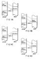
- FIG. 14A For example, a case will be examined wherein a program is to break at instruction 1 of code 1 stored in the IMEM, as shown in FIG. 14A.
- instruction 1 at address A on the IMEM is replaced by the dbreak command, as shown in FIG. 14B.
- the dbreak command is replaced by instruction 2.
- FIG. 14D After that, when code 1 is overlaid on code 2 again, as shown in FIG. 14D, the dbreak command is removed from address A. For this reason, when the output value of the program counter reaches address A, instruction 1 is executed, and no break occurs.
- a debugging apparatus comprising: a first storage means for storing a plurality of program codes identified by identifiers; a second storage means having at least one storage area, a program code to be executed of the plurality of program codes stored in the first storage means being stored in the storage area; a first variable storage area for storing the identifier of the program code, which is stored in the storage area of the second storage means; and a controlling means configured to break execution of the program code when an identifier set in an input command matches the identifier stored in the first variable storage area at an address designated by the input command.
- a debugging method comprising: transferring a program code to be executed of a plurality of program codes to a storage area of a second storage device, the plurality of program codes being stored -in a first storage device and identified by identifiers; comparing an output value of a program counter and an address set in an input break command; comparing, when the output value of the program counter matches the address set in the break command as a result of comparison, an identifier set by the break command and an identifier of the program code that has been transferred to the storage area of the second storage device; and breaking, when the identifiers match as a result of comparison of the identifiers, execution of the program code.
- FIG. 1 shows an example of the overall arrangement of a debugging apparatus applied to the first embodiment.
- a chip 2 of a processor is mounted on a circuit board 1.
- This chip 2 is connected to a JTAG (Joint Test Action Group) controller 4 via a JTAG port 3.
- This JTAG controller 4 is connected to a personal computer (or workstation) 5.
- the personal computer 5 stores a debugger 6 for controlling to debug a program on the chip 2, and a simulator 7 for simulating the program.
- FIG. 2 shows a schematic arrangement of the processor arranged in the chip 2.
- a CPU 11 incorporates an IMEM 12 as an instruction memory.
- the CPU 11 is connected to a bus 13.
- An SDRAM 15 as a main memory is connected to the bus 13 via an SDRAMC (SDRAM controller) 14.
- SDRAM 15 has a memory size as large as about 256 Mbits, and is arranged outside the chip 2.
- a DMAC (DMA controller) 16 that controls data transfer between the IMEM 12 and SDRAM 15 is connected to the bus 13.
- the IMEM 12 comprises a high-speed RAM from which an instruction can be fetched within, e.g., one instruction cycle, and which has a size of about several ten K bits.
- FIGS. 1 and 2 The detailed arrangement of FIGS. 1 and 2 will be explained below with reference to FIGS. 3 and 4. Note that the same reference numerals in FIGS. 3 and 4 denote the same parts as in FIGS. 1 and 2.
- a code to be overlaid will be explained first using FIG. 3.
- the code to be overlaid has two different addresses.
- a code is set in a relatively low-speed memory (SDRAM in this embodiment) before it is executed.
- the address at that time is called a location address.
- address 1 indicates the location address.
- This code 1 is stored in the IMEM when it is executed.
- the address at that time is called an execution address of code 1.
- Address A shown in FIG. 3 is an example of the execution address of instruction 1 of code 1.
- one code does not have a plurality of execution addresses. That is, assume that a given code is never stored in two or more execution addresses of the IMEM.
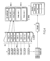
- FIG. 4 shows details of the arrangement of FIGS. 1 and 2.
- the SDRAM 15 stores an OS (operating system) as a control program, and codes of a plurality of tasks 1, 2, and so on.
- the IMEM 12 is split into, e.g., two banks. Bank 1 stores a copy of the resident part of the OS.
- the IMEM 12 has, e.g., four overlay areas 1, 2, 3, and 4. The numbers of overlay areas and tasks may be arbitrarily set, and at least one overlay area may be assured. Overlay areas 1 and 2 are assured on bank-1, and-overlay areas 3 and 4 are assured on bank 2. Codes of each task are replaced on each of these overlay areas.
- the code of task 1 in the SDRAM 15 is divided into code 1-1, and codes 1-2-1 to .1-4-2.
- Each code is copied to the corresponding overlay area of the IMEM 12 before execution. That is, code 1-1 is copied to overlay area 1, and codes 1-2-1 and 1-2-2 are copied to overlay area 2. Also, code 1-3 is copied to overlay area 3, and codes 1-4-1 and 1-4-2 are copied to overlay area 4. That is, overlay area 2 is shared by codes 1-2-1 and 1-2-2, and overlay area 4 is shared by codes 1-4-1 and 1-4-2.
- the codes of each task are set in advance by, e.g., a programmer.
- Each code has an ID serving as an identifier.
- This ID has, e.g., a 16-bit length: the first 8 bits record the identifier of a task, and the remaining 8 bits record a unique identifier in the task.
- the ID of code 1-1 is 0x0101, and that of code 1-2-1 is 0x0102.
- the ID of each code is set by a language tool.
- variable storage areas OVR1, OVR2, OVR3, and OVR4 are assured in correspondence with the respective overlay areas. That is, variable storage areas OVR1, OVR2, OVR3, and OVR4 respectively correspond to overlay areas 1, 2, 3, and 4.
- Each of these variable storage areas OVR1, OVR2, OVR3, and OVR4 indicates a code and an overlay area which stores a copy of that code. For example, when code 1-1 is copied to overlay area 1, variable storage area OVR1 stores ID 0x0101 of code 1-1.
- These variable storage areas OVR1 to OVR4 can be looked up by all of the debugger, simulator, OS, and task.
- the IDs and the variable storage areas OVR1 to OVR4 are stored in, e.g., the SDRAM 15.
- variable storage areas OVR1, OVR2, OVR3, and OVR4 form the core of the operating system, and are updated by a kernel or task management program-that resides on the -IMEM 12.
- the kernel switches a task from task 2 to task 1, it changes the contents of variable storage area OVR1 to 0x0101.
- code 1-1 in the SDRAM 15 is copied to overlay area 1 of the IMEM 12.
- Task 1 copies, e.g., code 1-3 to overlay area 3.
- the contents of variable storage area OVR3 are changed to 0x0104 first.
- the DMAC 16 is activated to copy code 1-3 to overlay area 3. Overlay areas 1 and 3 are assured on different banks. For this reason, execution of code 1-1 and DMA transfer of code 1-3 are parallelly executed. Note that each code forms a section as a building unit of a program.
- a breakpoint is input from, e.g., a keyboard of the personal computer (or workstation) 5 after the debugger 6 is activated. More specifically, the breakpoint is set by a break command input from the keyboard.
- FIG. 5 shows the input format of the break command.
- the execution address to break a task the variable storage area name indicating the overlay area, and the ID are designated after "dbg>break".
- the execution address is address A
- the variable storage area name is OVR1
- the ID is 0x0101. This description means that execution breaks when the output value of a program counter matches execution address A, and when a code specified by the ID is stored in overlay area 1 designated by the variable storage area name.
- FIG. 6 shows the operation upon debugging by the simulator 7 shown in FIG. 4.
- the debugger 6 supplies the break condition (execution address, variable storage area name, and ID) to the simulator 7.
- the simulator 7 holds this break condition.
- the simulator compares the value of-its program counter (PC) and the execution address while executing instructions (ST1). If they match, the simulator compares if the set variable storage area name matches an actual variable, and if the set ID matches an actual ID (ST2). That is, in the example shown in FIG. 5, the simulator compares if the value of variable storage area OVR1 is equal to the ID (0x0101) of code 1-1. If they match, the simulator breaks execution (ST3).
- variable storage area name and ID set by the break command do not match the ID stored in one of variable storage areas OVR1 to OVR4. For this reason, no break occurs.
- code 1 is copied from the SDRAM 15 to the IMEM 12. In this state, when the output value of the program counter matches address A of the breakpoint, the variable storage area name and ID set by the break command match the ID stored in one of variable storage areas OVR1 to OVR4. Therefore, a break reliably occurs at the set address.
- debugger 6 or a kernel (not shown) may hold the variable storage area name and ID. Also, the simulator may directly look up variable storage areas OVR1 to OVR4.
- the value of the program counter (PC) is compared with the execution address., and if they match, it is compared if the set variable storage area name matches an actual variable, and if the set ID matches an actual ID.
- this order of comparison may be reversed. That is, it may be compared first if the set variable storage area name matches an actual variable, and if the set ID matches an actual ID, and if they match, the value of the program counter (PC) may be compared with the execution address.
- FIG. 7 shows an object for a debugger in this embodiment.
- each section in an execution program for a debugger, each section (code) has, as debug information, the location address and execution address corresponding to the head of the section.
- the location address indicates the start address of the section when that section is stored in the SDRAM 15.
- the execution address indicates the start address of the section when that section is stored in the IMEM 12.
- instruction 1 stored at address A of the IMEM 12 shown in FIG. 8A is saved to a monitor area (not shown) of the debugger 6. That is, instruction 1 stored at address A of the IMEM 12 is saved to the monitor area (not shown) of the debugger 6 on the basis of the execution address to break the program of the break command.
- a dbreak command as a break command is written at address A, as shown in FIG. 8B.
- instruction 1 of code 1 stored in the SDRAM 15 is overwritten by the dbreak command.
- the location address of instruction 1 on the SDRAM 15 is obtained as follows.
- the debugger acquires a debugger object of a code to which the execution address belongs, on the basis of the execution address of the break command.
- the location address of the head of the section is detected from this debugger object.
- an offset (relative address) from the location address to instruction 1 in the section address 1 on the SDRAM 15 can be obtained.
- the dbreak command is written at both the execution address on the IMEM 12 and the location address on the SDRAM 15. For this reason, even when code 1 on the IMEM 12 is replaced by another code, and-the dbreak command is overwritten by another command, code 1 is copied again from the SDRAM 15 to the IMEM 12 upon executing code 1. As a result, the dbreak command is copied again onto the IMEM. Therefore, since the dbreak command never disappears from the IMEM 12, a break can reliably occur at address A.
- the ID is set for each code, and the code copied to each overlay area of the IMEM 12 is managed by the code ID stored in variable storage areas OVR1 to OVR4.
- the break command that sets a breakpoint has a variable storage area name and ID in correspondence with the execution address to break a program.
- the variable storage area name and ID set in the break command do not match those in the variable storage area.
- no break occurs.
- the corresponding code is copied from the SDRAM 15 to the IMEM 12.
- the variable storage area name and ID in the variable storage area match those set in the break command.
- the break command is written at both the execution address of a code stored in the IMEM 12 and the location address of that code stored in the SDRAM 15. Hence, even when the code stored in the IMEM 12 is replaced by another code, the break command is never lost. Therefore, a break can reliably occur at the address where the break command is set.
- variable storage area has a plurality of areas. For this reason, even when a plurality of debug areas are set, a break can reliably occur at a desired address.
- the kernel and task update the contents of variable storage areas OVR1 to OVR4.
- the DMAC (DMA controller) 16 updates the contents of variable storage areas OVR1 to OVR4.
- variable storage areas OVR1 to OVR4 a method in which the hardware of the DMAC 16 updates the contents of variable storage areas OVR1 to OVR4 and a method in which a function of launching the DMAC 16 is provided, and the contents of variable storage areas OVR1 to OVR4 are updated by software using this function are available.
- the simulator may be provided with a function of updating the contents of variable storage areas OVR1 to OVR4. However, in this case, execution cannot be broken by a real device.
- variable storage areas OVR1 to OVR4 since the DMAC 16 updates the contents of variable storage areas OVR1 to OVR4, the user need not change variable storage areas OVR1 to OVR4 upon executing an overlay that he or she set. For this reason, the load on the user can be reduced.
- FIGS. 9A and 9B show the third embodiment of the present invention.
- a debugger may generate a table which has codes and IDs corresponding to the codes on the basis of a source program. With this arrangement, the user need only input a break command, and the load on the user can be further reduced.
- a compiler may generate a table which has codes and IDs corresponding to the codes on the basis of a source program.
- the break command is input from the keyboard.
- the present invention is not limited to this.
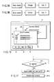
- FIG. 10 shows an example in which the break command is input using a GUI (Graphical User Interface) according to the fourth embodiment of the present invention.
- a source window 32 of the debugger 6 is displayed on a display 31 of the personal computer or workstation.
- This source window 32 displays a source program described in C or assembler.
- This source program is formed by the location or execution addresses, and instructions. Whether the location or execution addresses are to be displayed can be arbitrarily set by the user.
- a source program which displays the location addresses and that which displays the execution addresses can be displayed on independent windows.
- a window 321 shown in FIG. 10 displays a source program including location addresses
- a window 322 displays a source program including execution addresses.
- either of the windows 321 and 322 can be displayed, or both the windows 321 and 322 can be simultaneously displayed.
- an overlay area, the source program of which is to be displayed, can be selected.
- a plurality of icons 33, 34, and 35 used to instruct operations of the debugger 6 are displayed near the source window 32. Of these icons, the icon 35 is used to instruct generation of a break command.
- FIG. 11 shows a schematic operation of the debugger 6.
- the debugger 6 obtains the execution address, variable storage area name, and ID from debug information of the debugger execution program shown in FIG. 7 (ST12), and generates the break command based on them (ST13).
- the source window displays the location addresses
- the execution address is acquired from the debug information, and is set in the break command. Note that this embodiment is not limited to generation of the break command itself, but information corresponding to the break command may be generated.
- the user need only move the cursor to a desired line of the source program displayed on the display 31, and click the icon 35 used to generate a break command. Therefore, since the user need not recognize the variable storage area name and ID, the operability can be further improved.
Landscapes
- Engineering & Computer Science (AREA)
- Theoretical Computer Science (AREA)
- Computer Hardware Design (AREA)
- Quality & Reliability (AREA)
- Physics & Mathematics (AREA)
- General Engineering & Computer Science (AREA)
- General Physics & Mathematics (AREA)
- Debugging And Monitoring (AREA)
Applications Claiming Priority (2)
| Application Number | Priority Date | Filing Date | Title |
|---|---|---|---|
| JP2002152961 | 2002-05-27 | ||
| JP2002152961A JP3764405B2 (ja) | 2002-05-27 | 2002-05-27 | デバッグ装置及びデバッグ方法 |
Publications (2)
| Publication Number | Publication Date |
|---|---|
| EP1367490A2 true EP1367490A2 (de) | 2003-12-03 |
| EP1367490A3 EP1367490A3 (de) | 2008-03-05 |
Family
ID=29417159
Family Applications (1)
| Application Number | Title | Priority Date | Filing Date |
|---|---|---|---|
| EP02016970A Withdrawn EP1367490A3 (de) | 2002-05-27 | 2002-08-02 | Fehlerbeseitigungsvorrichtung und Verfahren |
Country Status (6)
| Country | Link |
|---|---|
| US (1) | US7043717B2 (de) |
| EP (1) | EP1367490A3 (de) |
| JP (1) | JP3764405B2 (de) |
| KR (1) | KR100526384B1 (de) |
| CN (1) | CN1231836C (de) |
| TW (1) | TWI241523B (de) |
Families Citing this family (12)
| Publication number | Priority date | Publication date | Assignee | Title |
|---|---|---|---|---|
| JP4202673B2 (ja) * | 2002-04-26 | 2008-12-24 | 株式会社東芝 | システムlsi開発環境生成方法及びそのプログラム |
| US7634640B2 (en) * | 2002-08-30 | 2009-12-15 | Infineon Technologies Ag | Data processing apparatus having program counter sensor |
| US8020148B2 (en) * | 2002-09-23 | 2011-09-13 | Telefonaktiebolaget L M Ericsson (Publ) | Bi-directional probing and testing of software |
| US20050060690A1 (en) * | 2003-09-15 | 2005-03-17 | Kuo-Jung Tung | Microprocessor system with software emulation processed by auxiliary hardware |
| KR100725502B1 (ko) * | 2005-09-09 | 2007-06-08 | 삼성전자주식회사 | 전자장치, 전자장치 시스템 및 전자장치의 제어방법 |
| JP2009043061A (ja) * | 2007-08-09 | 2009-02-26 | Oki Electric Ind Co Ltd | デバッグ装置及びデバッグ方法 |
| JP5163230B2 (ja) * | 2008-03-31 | 2013-03-13 | 富士通株式会社 | 検証プログラム、該プログラムを記録した記録媒体、検証装置、および検証方法 |
| KR101636521B1 (ko) * | 2010-03-26 | 2016-07-06 | 삼성전자주식회사 | 코드 오버레이 생성 장치 및 방법 |
| US8572579B2 (en) * | 2010-08-19 | 2013-10-29 | Oracle International Corporation | Break on next called function or method in java debugger agent |
| CN104346274B (zh) * | 2013-07-29 | 2017-06-06 | 国际商业机器公司 | 程序调试器及一种程序的调试方法 |
| US20170147471A1 (en) * | 2014-05-29 | 2017-05-25 | Hewlett Packard Enterprise Development Lp | Isolating production environment debugging sessions |
| TWI751706B (zh) * | 2020-09-16 | 2022-01-01 | 宏碁股份有限公司 | 自動產生開發解決方案的方法及裝置 |
Family Cites Families (24)
| Publication number | Priority date | Publication date | Assignee | Title |
|---|---|---|---|---|
| JPS57108942A (en) | 1980-12-25 | 1982-07-07 | Fujitsu Ltd | Address stop system for overlay program |
| JPS57137951A (en) | 1981-02-18 | 1982-08-25 | Nec Corp | Data processor |
| JPS58112149A (ja) | 1981-12-25 | 1983-07-04 | Hitachi Ltd | オ−バ−レイプログラムのアドレス変換方式 |
| JPH02300943A (ja) | 1989-05-16 | 1990-12-13 | Nec Corp | デバッグサポート方式 |
| JPH03113648A (ja) | 1989-09-28 | 1991-05-15 | Mitsubishi Electric Corp | プログラムデバツグ方式 |
| JPH0464139A (ja) | 1990-07-04 | 1992-02-28 | Toshiba Corp | プログラムローディング装置 |
| JPH04145544A (ja) | 1990-10-05 | 1992-05-19 | Nec Corp | デバッグ装置 |
| JP2869379B2 (ja) | 1996-03-15 | 1999-03-10 | 三菱電機株式会社 | プロセッサ合成システム及びプロセッサ合成方法 |
| JP2856152B2 (ja) | 1996-05-30 | 1999-02-10 | 日本電気株式会社 | カーネルデバッガにおけるソフトウェアブレークポイント管理方式 |
| JPH1185565A (ja) * | 1997-09-12 | 1999-03-30 | Yaskawa Electric Corp | Cpuのデバッグ方法およびそのシステム |
| JP3671667B2 (ja) * | 1998-03-31 | 2005-07-13 | セイコーエプソン株式会社 | マイクロコンピュータ、電子機器及びデバッグシステム |
| EP0992906B1 (de) | 1998-10-06 | 2005-08-03 | Texas Instruments Inc. | Vorrichtung und Verfahren für einen Software-Haltepunkt während eines Verzögerungsschlitzes |
| JP2000250777A (ja) | 1999-02-25 | 2000-09-14 | Canon Inc | 情報処理装置と情報処理方法、及び記憶媒体 |
| US6412106B1 (en) * | 1999-06-16 | 2002-06-25 | Intervoice Limited Partnership | Graphical system and method for debugging computer programs |
| JP2001034504A (ja) * | 1999-07-19 | 2001-02-09 | Mitsubishi Electric Corp | ソースレベルデバッガ |
| JP2001282572A (ja) | 2000-03-29 | 2001-10-12 | Canon Inc | プログラムデバッグ装置および方法 |
| KR100337149B1 (ko) | 2000-07-05 | 2002-05-18 | 권 기 홍 | 프로그램 테스트 및 디버깅이 용이한 중앙처리장치 |
| US6766511B1 (en) * | 2000-07-10 | 2004-07-20 | International Business Machines Corporation | Apparatus and method for performing symbolic resolution of modules using static representations of a trace |
| JP2002041285A (ja) * | 2000-07-28 | 2002-02-08 | Toshiba Corp | データ処理装置およびデータ処理方法 |
| JP2002073370A (ja) | 2000-08-25 | 2002-03-12 | Nec Microsystems Ltd | デバッグ支援装置およびその装置によるデバッグ方法 |
| KR100802606B1 (ko) * | 2001-04-13 | 2008-02-13 | 엘지전자 주식회사 | 데이터의 천이 상태에 따른 디버깅 장치 및 방법 |
| US6836884B1 (en) * | 2001-06-04 | 2004-12-28 | Microsoft Corporation | Method and system for editing software programs |
| US20030074650A1 (en) * | 2001-10-17 | 2003-04-17 | Tankut Akgul | Debugger operating system for embedded systems |
| US6892325B2 (en) * | 2001-11-27 | 2005-05-10 | International Business Machines Corporation | Method for displaying variable values within a software debugger |
-
2002
- 2002-05-27 JP JP2002152961A patent/JP3764405B2/ja not_active Expired - Fee Related
- 2002-08-01 US US10/208,839 patent/US7043717B2/en not_active Expired - Lifetime
- 2002-08-02 EP EP02016970A patent/EP1367490A3/de not_active Withdrawn
- 2002-10-15 TW TW091123684A patent/TWI241523B/zh not_active IP Right Cessation
- 2002-10-30 KR KR10-2002-0066440A patent/KR100526384B1/ko not_active Expired - Fee Related
- 2002-10-31 CN CNB021482519A patent/CN1231836C/zh not_active Expired - Fee Related
Also Published As
| Publication number | Publication date |
|---|---|
| EP1367490A3 (de) | 2008-03-05 |
| JP3764405B2 (ja) | 2006-04-05 |
| JP2003345624A (ja) | 2003-12-05 |
| CN1462938A (zh) | 2003-12-24 |
| TWI241523B (en) | 2005-10-11 |
| US20030221188A1 (en) | 2003-11-27 |
| US7043717B2 (en) | 2006-05-09 |
| CN1231836C (zh) | 2005-12-14 |
| KR20030091640A (ko) | 2003-12-03 |
| KR100526384B1 (ko) | 2005-11-08 |
Similar Documents
| Publication | Publication Date | Title |
|---|---|---|
| US7533246B2 (en) | Application program execution enhancing instruction set generation for coprocessor and code conversion with marking for function call translation | |
| US7950001B2 (en) | Method and apparatus for instrumentation in a multiprocessing environment | |
| JP5488697B2 (ja) | マルチコアプロセッサシステム、同期制御方法、および同期制御プログラム | |
| US7836430B2 (en) | Reversing execution of instructions in a debugger | |
| Wulf et al. | Overview of the Hydra operating system development | |
| US7043717B2 (en) | Debugging apparatus and method | |
| JPH08278918A (ja) | エンディアンタスクを実行するシステム及び方法 | |
| US20070168985A1 (en) | Thread debugging device, thread debugging method and information storage medium | |
| US20100153786A1 (en) | Processor, multiprocessor, and debugging method | |
| US7676774B2 (en) | System LSI verification system and system LSI verification method | |
| TWI599876B (zh) | 開機自我測試中的除錯方法以及使用該方法的裝置 | |
| US8612720B2 (en) | System and method for implementing data breakpoints | |
| US20070101115A1 (en) | Information processing device, bios processing method and program | |
| US20030217355A1 (en) | System and method of implementing a virtual data modification breakpoint register | |
| EP1227404B1 (de) | Transparenter Zugriff zu gemeinschaftlichem Speicher in einem Sofwareentwicklungssystem | |
| JP5811211B2 (ja) | マルチコアプロセッサシステム、マルチコアプロセッサシステムの制御方法、およびマルチコアプロセッサシステムの制御プログラム | |
| JP3503504B2 (ja) | デバッグ処理システムと計算機およびデバッグ処理方法 | |
| JPH1124960A (ja) | グラフィックスlsi | |
| JPH10187480A (ja) | エミュレータ | |
| JP2002366378A (ja) | プログラムのデバッグ装置及びデバッグ方法、並びに記憶媒体 | |
| JPS6113615B2 (de) | ||
| JP3120841B2 (ja) | インサーキットエミュレータ | |
| JPH0883198A (ja) | プログラムシミュレーション装置 | |
| JP2000227861A (ja) | デバッグ方法及びデバッグ装置 | |
| JP2003015904A (ja) | デバッガ処理方法および記録媒体 |
Legal Events
| Date | Code | Title | Description |
|---|---|---|---|
| PUAI | Public reference made under article 153(3) epc to a published international application that has entered the european phase |
Free format text: ORIGINAL CODE: 0009012 |
|
| 17P | Request for examination filed |
Effective date: 20020802 |
|
| AK | Designated contracting states |
Kind code of ref document: A2 Designated state(s): AT BE BG CH CY CZ DE DK EE ES FI FR GB GR IE IT LI LU MC NL PT SE SK TR |
|
| AX | Request for extension of the european patent |
Extension state: AL LT LV MK RO SI |
|
| PUAL | Search report despatched |
Free format text: ORIGINAL CODE: 0009013 |
|
| AK | Designated contracting states |
Kind code of ref document: A3 Designated state(s): AT BE BG CH CY CZ DE DK EE ES FI FR GB GR IE IT LI LU MC NL PT SE SK TR |
|
| AX | Request for extension of the european patent |
Extension state: AL LT LV MK RO SI |
|
| 17Q | First examination report despatched |
Effective date: 20080903 |
|
| AKX | Designation fees paid |
Designated state(s): DE FR GB |
|
| STAA | Information on the status of an ep patent application or granted ep patent |
Free format text: STATUS: THE APPLICATION IS DEEMED TO BE WITHDRAWN |
|
| 18D | Application deemed to be withdrawn |
Effective date: 20090114 |