EP1367372A1 - Wind protection device for a balance and balance with a wind protection device - Google Patents
Wind protection device for a balance and balance with a wind protection device Download PDFInfo
- Publication number
- EP1367372A1 EP1367372A1 EP02100577A EP02100577A EP1367372A1 EP 1367372 A1 EP1367372 A1 EP 1367372A1 EP 02100577 A EP02100577 A EP 02100577A EP 02100577 A EP02100577 A EP 02100577A EP 1367372 A1 EP1367372 A1 EP 1367372A1
- Authority
- EP
- European Patent Office
- Prior art keywords
- protection device
- wind protection
- rear wall
- weighing
- wind
- Prior art date
- Legal status (The legal status is an assumption and is not a legal conclusion. Google has not performed a legal analysis and makes no representation as to the accuracy of the status listed.)
- Granted
Links
Images


Classifications
-
- G—PHYSICS
- G01—MEASURING; TESTING
- G01G—WEIGHING
- G01G21/00—Details of weighing apparatus
- G01G21/28—Frames, Housings
- G01G21/286—Frames, Housings with windshields
-
- G—PHYSICS
- G01—MEASURING; TESTING
- G01G—WEIGHING
- G01G23/00—Auxiliary devices for weighing apparatus
- G01G23/18—Indicating devices, e.g. for remote indication; Recording devices; Scales, e.g. graduated
- G01G23/20—Indicating weight by mechanical means
- G01G23/30—Indicating weight by mechanical means with means for illuminating the scale
Landscapes
- General Physics & Mathematics (AREA)
- Physics & Mathematics (AREA)
- Devices For Use In Laboratory Experiments (AREA)
- Instrument Panels (AREA)
- Loading And Unloading Of Fuel Tanks Or Ships (AREA)
- Liquid Crystal (AREA)
- Catching Or Destruction (AREA)
- Forklifts And Lifting Vehicles (AREA)
- Laminated Bodies (AREA)
- Body Structure For Vehicles (AREA)
- Projection Apparatus (AREA)
- Glass Compositions (AREA)
- Devices For Indicating Variable Information By Combining Individual Elements (AREA)
- Window Of Vehicle (AREA)
- Bridges Or Land Bridges (AREA)
- Package Frames And Binding Bands (AREA)
- Supporting Of Heads In Record-Carrier Devices (AREA)
- Automatic Cycles, And Cycles In General (AREA)
Abstract
Description
Die Erfindung betrifft eine Windschutzvorrichtung für eine Waage sowie eine mit dieser Vorrichtung versehene Waage.The invention relates to a wind protection device for a balance and a balance provided with this device.
Die Präzision einer Waage ist von verschiedenen Faktoren abhängig. Von Bedeutung sind Luftströmungen, die während einer Messung auf die im Wägeraum vorgesehene Waagschale einwirken. Zur Vermeidung störender Luftströmungen sind Waagen daher meist mit Vorrichtungen versehene, durch die der Wägeraum gegen Einwirkungen von Luftströmen geschützt wird.The precision of a scale depends on several factors dependent. Air currents are important during a Act measurement on the weighing pan provided in the weighing room. Scales are therefore mostly used to avoid disturbing air currents equipped with devices through which the weighing room against Effects of air currents is protected.
Eine Windschutzvorrichtung dieser Art ist beispielsweise aus [1], Patentschrift CH-677 029 A5, bekannt. Die dort beschriebene Windschutzvorrichtung besteht aus vier oder mehr gelenkig miteinander verbundenen Teilwänden, von denen mindestens eine einen U-förmigen Rahmen aufweist, in den eine Platte oder Scheibe eingeschoben ist, die bei Bedarf, zum Einwägen oder Beschicken der Waage, entfernt werden kann. An der Oberkante der Teilwand, welche die Rückwand bildet, ist ferner ein Deckel angelenkt, mittels dessen der Wägeraum ebenfalls geöffnet werden kann.A windbreak device of this type is, for example, from [1], patent specification CH-677 029 A5, known. The one described there Wind protection device consists of four or more articulated interconnected part walls, at least one of which has a U-shaped frame in which a plate or Is inserted, if necessary, for weighing or Loading the scale, can be removed. At the top of the Partial wall, which forms the rear wall, is also a cover hinged, by means of which the weighing room can also be opened can.
Eine weitere, in [2], Patentschrift CH-687 836 A5, offenbarte Windschutzvorrichtung ist für Waagen vorgesehen, die einen Sockel mit einer damit verbundenen, feststehenden Rückwand und einer mittels Streben mit der Rückwand verbundenen Frontscheibe aufweisen. Ferner sind zwei, die Seitenwände bildende Schiebetüren vorgesehen, welche im Bereich der Vorderkanten Führungsmittel aufweisen, welche untere Längsführungen umgreifen.Another, disclosed in [2], patent CH-687 836 A5 Wind protection device is intended for scales, the one Base with a fixed rear wall and a front window connected to the rear wall by means of struts exhibit. There are also two that form the side walls Sliding doors are provided, which are in the area of the front edges Guide means which have lower longitudinal guides embrace.
Aus [3], Offenlegungsschrift DE 198 49 399 A1, ist eine Windschutzvorrichtung bekannt, die mittels einer Verriegelungsvorrichtung lösbar mit dem Sockel einer Waage verbindbar ist. Ferner erlaubt diese Vorrichtung ein einfaches Auswechseln von Windschutzscheiben, wodurch ein bequemes Reinigen der Vorrichtung ermöglicht wird.From [3], published application DE 198 49 399 A1, is one Known windshield device by means of a Locking device releasable with the base of a scale is connectable. Furthermore, this device allows a simple one Replacing windshields, which makes them convenient Cleaning the device is made possible.
Aus [4] und [5], Offenlegungsschriften DE 37 41 313 A1 und DE 199 48 754 A1, sind zudem Windschutzvorrichtungen mit motorisch betätigbaren Elementen bekannt.From [4] and [5], published documents DE 37 41 313 A1 and DE 199 48 754 A1, are also wind protection devices with motor actuatable elements known.
Bei der in [4] beschriebenen Vorrichtung sind wenigstens zwei zylinderförmig gebogene Wandelemente vorgesehen, die zum Öffnen und Schliessen des Wägeraumes gegeneinander verschiebbar sind. Die aus [5] bekannte Vorrichtung weist wenigstens zwei Wandelemente auf, die unabhängig voneinander motorisch bewegbar sind.In the device described in [4] there are at least two cylindrical curved wall elements are provided that can be opened and closing the weighing room are mutually displaceable. The device known from [5] has at least two Wall elements that can be moved independently of each other by motor are.
Bei all den beschriebenen Windschutzvorrichtungen sind die Zugänge zum Wägeraum entweder fest vorgegeben oder vom Anwender durch Entfernen eines oder mehrerer Elemente der Vorrichtung zu schaffen.In all the wind protection devices described are the Access to the weighing room either predefined or by the user by removing one or more elements of the device create.
Für den Anwender wäre es jedoch oft von Vorteil, wenn er die Windschutzvorrichtung, ohne das Entfernen einzelner Vorrichtungsteile, mit minimalem Aufwand seinen Bedürfnissen anpassen könnte.However, it would often be an advantage for the user to use the Windbreak device without removing individual Device parts, with minimal effort to meet his needs could adjust.
Insbesondere wäre es von Vorteil, wenn er den Zugang zum Wägeraum selbst frei wählen könnte. In particular, it would be advantageous if he had access to the Weighing room could choose freely.
Der vorliegenden Erfindung liegt daher die Aufgabe zugrunde, eine derart verbesserte Windschutzvorrichtung sowie eine mit dieser Windschutzvorrichtung versehene Waage zu schaffen.The present invention is therefore based on the object such an improved wind protection device and one with to provide this draft shield device.
Diese Aufgabe wird mit einer Windschutzvorrichtung und einer Waage gelöst, welche die in den unabhängigen Ansprüchen angegebenen Merkmale aufweist. Vorteilhafte Ausgestaltungen der Erfindung sind in weiteren Ansprüchen angegeben.This task is done with a windbreak and a Libra solved which the in the independent claims Features specified. Advantageous embodiments of the Invention are specified in further claims.
Die erfindungsgemässe Windschutzvorrichtung weist einen den Wägeraum einer Waage, in welchem die Waagschale angeordnet ist, teilweise umfassenden, aus mindestens zwei flächigen Elementen bestehenden, windabweisenden Körper auf. Der Körper ist lose handhabbar in wenigstens zwei verschiedenen Stellungen positionierbar, in denen je wenigstens eine Öffnung für den Zugriff in den Wägeraum geschaffen wird. Der Körper lässt sich durch den Anwender dabei derart positionieren, dass die realisierbaren Öffnungen einen Zugriff in den Wägeraum aus unterschiedlichen Richtungen erlauben.The wind protection device according to the invention has a Weighing room of a balance in which the weighing pan is arranged partially comprehensive, consisting of at least two flat elements existing, wind-repellent body. The body is loose manageable in at least two different positions positionable, in each of which at least one opening for the Access to the weighing room is created. The body can be positioned by the user so that the viable openings provide access to the weighing room allow different directions.
Die Windschutzvorrichtung, kann durch den Anwender daher mit einfachsten Massnahmen den vorliegenden Bedürfnissen angepasst werden. Dabei kann der Körper entweder direkt auf dem Waagengehäuse oder auf einem Sockel platziert werden.The windbreak device can therefore be used by the user simplest measures adapted to the existing needs become. The body can either directly on the Scale housing or placed on a base.
Bei vorzugsweisen Ausgestaltungen des Körpers, beispielsweise in der Form eines L- oder V- oder U-Profils, kann dieser derart positioniert werden, dass ein Zugriff in den Wägeraum von vorn, von oben, von links oder von rechts oder von zwei Seiten gleichzeitig her möglich ist. Besonders vorteilhaft dabei ist, dass die erfindungsgemässe Windschutzvorrichtung in jeder der wählbaren Stellungen die Anforderungen an konventionelle Windschutzvorrichtungen insbesondere hinsichtlich Stabilität und Funktionalität vollständig erfüllt. In preferred configurations of the body, for example in the shape of an L or V or U profile, this can be so positioned that access to the weighing room from the front, from above, from left or from right or from two sides is possible at the same time. It is particularly advantageous that the inventive wind protection device in each of the selectable positions the requirements for conventional Wind protection devices, in particular with regard to stability and Functionality completely fulfilled.
Der Körper besteht vorzugsweise aus wenigstens zwei fest oder gelenkig miteinander verbundenen, ebenen oder gekrümmten flächigen Elementen, die, wie die Bestandteile konventioneller Windschutzvorrichtungen, beispielsweise aus Glas, Kunststoff und/oder Metall gefertigt sind. Auch ist ein einstückig gefertigter Körper denkbar.The body preferably consists of at least two solid or articulated, flat or curved flat elements, like the components of conventional Wind protection devices, for example made of glass, plastic and / or metal are made. Also is one piece manufactured body conceivable.
Im Rahmen der Erfindung ist auch eine Windschutzvorrichtung für eine Waage zu betrachten, die eine den Wägeraum nach einer Seite begrenzende Rückwand aufweist, welche aus einem das Umgebungslicht diffus transmittierenden Material gefertigt ist, so dass der Wägeraum vorteilhaft von hinten ausgeleuchtet werden kann, beziehungsweise das Umgebungslicht den Wägeraum durchfluten kann, andererseits jedoch hinter der Rückwand vorgesehene Teile der Waage nicht störend in Erscheinung treten. Eine solche Rückwand steht vorzugsweise annähernd senkrecht auf dem Wägeraumboden.Within the scope of the invention is also a wind protection device for a scale to look at, one the weighing room to one side has bounding rear wall, which from a Ambient light diffusely transmitting material is made so that the weighing room can be advantageously illuminated from behind can, or the ambient light the weighing room can flow through, but on the other hand behind the rear wall intended parts of the scale do not interfere with appearance. Such a rear wall is preferably approximately perpendicular the weighing room floor.
In einer bevorzugten Ausführungsform ist eine solche Rückwand mit einer Anzeige, insbesondere einer hintergrundbeleuchteten Flüssigkristallanzeige versehen. Dies erlaubt dem Anwender gleichzeitig auf die Waagschale beziehungsweise das Wägegut und die Anzeige zu blicken. Auch die Anordnung einer Beleuchtungsvorrichtung zur Beleuchtung der Rückwand von hinten kann vorgesehen werden.In a preferred embodiment, such a rear wall with a display, especially a backlit one Provide liquid crystal display. This allows the user simultaneously on the weighing pan or the weighing sample and to look at the ad. Even the arrangement of one Lighting device for illuminating the rear wall from the rear can be provided.
Insbesondere kann die Erfindung dadurch ausgeführt werden, dass die Rückwand abnehmbar und gegen eine andere Rückwand auswechselbar ausgestaltet ist.In particular, the invention can be carried out in that the back wall removable and against another back wall is designed to be exchangeable.
Die anhand des Körpers geschaffenen Öffnungen, durch die der Zugriff in den Wägeraum erfolgt, sind vorzugsweise durch weitere dreh- oder verschiebbare, windabweisende Elemente, beispielsweise Türelemente oder einen gegebenenfalls an der Rückwand angelenkten Deckel ganz oder teilweise verschliessbar. Die windabweisenden Elemente können dabei fest installiert oder durch den Anwender bei Bedarf montierbar sein. Insbesondere ist es zweckmässig, wenn der Körper in dessen Stellungen an das Gehäuse der Waage, den Sockel und/oder die Rückwand und/oder den Deckel angepasst ist.The openings created through the body through which the Access to the weighing room is preferably through others rotatable or slidable, wind-resistant elements, for example door elements or a possibly on the The hinged lid can be completely or partially closed. The wind-repellent elements can be permanently installed or can be assembled by the user if required. In particular is it is expedient if the body in its positions on the Housing of the scale, the base and / or the rear wall and / or the Lid is adjusted.
Die gegebenenfalls motorisch angetriebenen dreh- oder verschiebbaren windabweisenden Elemente sind bei Nichtgebrauch vorzugsweise innerhalb einer mit der Rückwand verbundenen Kammer deponierbar. In einer bevorzugten Ausgestaltung ist der Körper faltbar und ebenfalls innerhalb der Kammer deponierbar.The possibly motor-driven rotary or Slidable windproof elements are when not in use preferably within a chamber connected to the rear wall landfilled. In a preferred embodiment, the body foldable and also depositable inside the chamber.
Vorzugsweise wird der Körper in den wählbaren Stellungen fixiert. Dies kann mit einfachen Mitteln erfolgen. Beispielsweise können an angrenzenden Gehäuseteilen oder am Sockel Nuten, Kanten, Nocken oder Klammern vorgesehen sein. Möglich ist natürlich auch die Verwendung von Schrauben. Ferner kann das Gehäuse mit haftenden Schichten, beispielsweise Hartgummi, versehen sein, auf denen der positionierte Körper mittels Haftreibung gehalten wird. Der Körper kann jedoch auch durch sein Eigengewicht gehalten sein, so dass gegebenenfalls nur Positionshilfen vorgesehen sind, mittels derer der Körper rasch und präzise positionierbar ist.The body is preferably in the selectable positions fixed. This can be done with simple means. For example, on adjacent housing parts or on Base grooves, edges, cams or brackets may be provided. Of course, the use of screws is also possible. Further can the housing with adhesive layers, for example Hard rubber, provided on which the positioned body is held by means of static friction. However, the body can too be held by its own weight, so that if necessary only position aids are provided, by means of which the body can be positioned quickly and precisely.
In einer weiteren bevorzugten Ausgestaltung der Erfindung sind Sensoren, beispielsweise Schalter oder optoelektronische Bauelemente vorgesehen, mittels derer die gewählte Stellung des Körpers und/oder der installierte Körper selbst detektierbar sind. Die steuerbaren Elemente der Waage, wie motorisch angetriebene Türelemente, die Beleuchtungsvorrichtung oder die Anzeige sind daher entsprechend der gewählten Stellung des Körpers betätigbar, so dass ein optimaler Bedienungskomfort für den Anwender resultiert. In a further preferred embodiment of the invention Sensors, for example switches or optoelectronic Components provided by means of which the selected position of the Body and / or the installed body itself detectable are. Controllable elements of the scale, such as motorized powered door elements, the lighting device or the The display is therefore in accordance with the selected position of the Body operated, so that an optimal ease of use for results in the user.
Nachfolgend wird die Erfindung anhand von Zeichnungen näher erläutert. Dabei zeigt:
Figur 1- eine mit einer erfindungsgemässen Windschutzvorrichtung versehene Waage, deren Wägeraum, der durch einen U-profilförmigen Körper teilweise umfasst wird, durch Anheben eines Deckels von oben zugänglich ist,
Figur 2- die Waage aus
Figur 1, ohne den Körper, jedoch mit montierten Türelementen, Figur 3- den U-profilförmigen Körper aus
Figur 1, Figur 4- einen L-profilförmigen Körper,
Figur 5- den L-profilförmigen Körper aus
Figur 4 in einer vorzugsweisen Ausgestaltung mit gegeneinander gefalteten Schenkeln, Figur 6- die Waage aus
Figur 1 mit liegendem U-profilförmigem Körper, dessen Schenkel nach vorn gerichtet sind, und daher von vorn zugänglichem Wägeraum, Figur 7- die Waage aus
Figur 1 mit stehendem U-profilförmigem Körper, dessen Schenkel seitlich auf den Sockel abgestützt sind, und daher von vorn zugänglichem Wägeraum, - Figur 8
- die Waage aus
Figur 1 mit liegendem U-profilförmigem Körper, dessen Schenkel seitlich nach links gerichtet sind, und daher von der linken Seite her zugänglichem Wägeraum, - Figur 9
- die
Waage aus Figur 1 mit liegendem L-profilförmigem Körper, dessen Schenkel die rechte Seite und die Frontseite der Windschutzvorrichtung bilden, und daher von der linken Seite her zugänglichem Wägeraum, Figur 10- die
Waage aus Figur 1 mit U- profilförmigem Körper, dessen auf dem Sockel stehende Schenkel den Wägeraum frontseitig und rückseitig begrenzen und daher einen Zugriff in den Wägeraum von der linken und rechten Seite her erlauben, und Figur 11- eine weitere Ausführungsform der erfindungsgemässen Waage mit einer erfindungsgemässen Windschutzvorrichtung.
- Figure 1
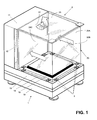
- a balance provided with a draft shield device according to the invention, the weighing chamber, which is partially surrounded by a U-shaped body, is accessible from above by lifting a lid,
- Figure 2
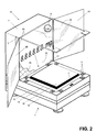
- the scale from Figure 1, without the body, but with mounted door elements,
- Figure 3
- the U-shaped body of Figure 1,
- Figure 4
- an L-shaped body,
- Figure 5
- 4 the L-profile-shaped body in a preferred embodiment with legs folded against one another,
- Figure 6
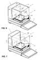
- 1 with a lying U-shaped body, the legs of which are directed towards the front, and therefore a weighing chamber accessible from the front,
- Figure 7
- 1 with standing U-shaped body, the legs of which are supported laterally on the base, and therefore weighing space accessible from the front,
- Figure 8
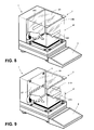
- 1 with a lying U-shaped body, the legs of which are directed laterally to the left, and therefore a weighing chamber accessible from the left,
- Figure 9
- 1 with a lying L-profile-shaped body, the legs of which form the right side and the front side of the draft shield, and therefore a weighing room accessible from the left side,
- Figure 10
- 1 with U-shaped body, the legs of which stand on the base, limit the weighing space on the front and rear and therefore allow access to the weighing space from the left and right sides, and
- Figure 11
- a further embodiment of the balance according to the invention with a wind protection device according to the invention.
Figur 1 zeigt eine mit einer erfindungsgemässen Windschutzvorrichtung
2 versehene Waage 1, deren Wägeraum unten durch
einen die Oberseite eines Sockels 13 bildenden Wägeraumboden 14,
oben durch einen Deckel 23, hinten durch eine Rückwand 22 und
vorn sowie seitlich durch einen U-profilförmigen Körper 20
begrenzt wird. Der U-profilförmige Körper 20, der Deckel 23, der
Wägeraumboden 14 und die Rückwand 22 sind in ihrer Grösse
aneinander angepasst, so dass dadurch der Wägeraum vollständig
abgeschlossen wird. Zum Einwägen oder Beschicken der Waage 1 in
der in Figur 1 gewählten Stellung des Körpers 20 ist daher der
Deckel 23 anzuheben, wonach der Wägeraum von oben zugänglich
ist.FIG. 1 shows a wind protection device according to the
Der, der auf dem Sockel 13 ruhende U-profilförmige Körper 20
weist drei flächige Elemente 20A, 20B, 20C auf, zwei gegen die
Rückwand 22 gerichtete Schenkel 20A, 20C, welche durch ein den
Wägeraum frontseitig begrenzendes Mittelstück 20B miteinander
verbunden sind. Die Schenkel 20A, 20C und das Mittelstück 20B
sind mittels Nocken 3, die auf dem Wägeraumboden 14 angeordnet
sind, beidseitig gehalten. The one, the
Wie aus der Figur 1 ersichtlich, ist ferner ein die hier nicht
sichtbare Wägezelle und die Wägeelektronik enthaltendes
Waagengehäuse 10 vorhanden. Der Sockel 13, welcher eine
Durchführung für den Durchtritt des die Waagschale 15 mit der
Wägezelle verbindenden Lastübertragungsglieds (hier ebenfalls
nicht sichtbar) besitzt, ist hier oberhalb des Waagengehäuses 10
angeordnet. Er kann mit dem Waagengehäuse 10 mittels Halterungen
verbunden sein oder auch in das Waagengehäuse 10 integriert
sein. Der Sockel 13, der vorwiegend als Auflage für den
windabweisenden Körper 20 dient, kann jedoch auch unterhalb des
Waagengehäuses angeordnet sein, beispielsweise als Stellfläche
für die Waage 1 einerseits und andererseits als Auflage für den
windabweisenden Körper 20 dienend.As can be seen from FIG. 1, this is also not one
visible load cell and containing the weighing
Aus Figur 1 ist ferner ersichtlich, dass der auf dem Gehäuse 10
der Waage 1 angeordnete Sockel 13 eine im rückwärtigen Teil der
Waage 1 stehende Kammer 11 trägt. Innerhalb der Kammer 11 können
beispielsweise elektronische Module oder, wie in Figur 2
gezeigt, eine Beleuchtungsvorrichtung 6 vorgesehen sein, welche
die einen Teil der Kammer 11 bildende Rückwand 22 des Wägeraums
beleuchtet. Die Kammer 11 ist ferner mit einem vorzugsweise
verschliessbaren Zugang 12 versehen, durch den Teile der
Windschutzvorrichtung 2 und/oder der gegebenenfalls faltbare
Körper 20 in die Kammer 11 einführbar und dort deponierbar sind.
Der Zugang 12 kann seitlich an der Kammer oder oberhalb
derselben angebracht sein und kann in letzterem Fall zum Öffnen
und Schliessen mit dem Deckel 23 verbunden sein.From Figure 1 it can also be seen that the on the housing 10th
the
Figur 2 zeigt eine Waage 1 ohne den U-profilförmigen Körper 20,
welcher beispielsweise zur Reinigung des Wägeraums entfernt
wurde. Zusätzlich oder alternativ zum U-profilförmigen Körper 20
können Türelemente 24 montiert werden, die gelenkig,
beispielsweise mittels eines Scharniers 16, mit der Rückwand 22
verbunden sind. Ebenso kann der Deckel 23, wie in der Figur
gezeigt, mit einem Scharnier 16 an der Rückwand 22 angelenkt
sein.FIG. 2 shows a
In der in Figur 2 gezeigten Ausgestaltung ist die Rückwand 22
aus einem das Umgebungslicht diffus transmittierenden Material
26, beispielsweise Mattglas, gefertigt, so dass der Wägeraum von
hinten gleichmässig ausgeleuchtet wird. Von Vorteil ist hierbei
die Lichtdurchflutung des Wägeraums einerseits und andererseits,
dass gegebenenfalls hinter der Rückwand 22 vorgesehene
Vorrichtungsteile, elektrische Module oder Kabel, nicht störend
in Erscheinung treten. Eine weitere Ausführungsform einer
solchen Rückwand wird weiter unten anhand der Figur 11
beschrieben.In the embodiment shown in FIG. 2, the
Weiterhin ist die Rückwand 22 an ihrem unteren Rand mit einer
Öffnung 17 versehen, die der Durchführung von elektrischen
Kabeln oder sonstigen Zuleitungen dient, an die beispielsweise
im Wägeraum zu verwendende Vorrichtungen anschliessbar sind. Der
Zugang zum Wägeraum durch die Kabeldurchführungsöffnung 17 kann
insbesondere dadurch erleichtert werden, dass die Rückwand 22
abnehmbar ausgestaltet ist, wie ebenfalls weiter unten anhand
der Figur 11 beschrieben wird. Auch ist eine Anordnung einer
oder mehrerer Kabeldurchführungsöffnungen 17, welche sich an
einem seitlichen oder dem oberen Rand der Rückwand 22 befinden,
denkbar.Furthermore, the
Die Rückwand 22 ist ferner mit einer Anzeige 5, beispielsweise
einer hintergrundbeleuchteten Flüssigkristallanzeige versehen,
was in Kombination mit der erfindungsgemässen Windschutzvorrichtung
2 besonders vorteilhaft ist. Die in der Rückwand 22
vorgesehene Anzeige 5 kann beispielsweise das Wägeresultat
ausgeben. Der Wägevorgang ist daher bequem durchführbar, da sich
sowohl die Anzeige 5, als auch die Waagschale 15 mit dem Wägegut
gleichzeitig im Blickfeld des Anwenders befinden. The
LCD- und LED-Anzeigen sowie deren Beschaltung sind beispielsweise in [6], Mool C. Gupta, Handbook of Photonics, CRC Press, Boca Raton 1997, Seiten 782 □ 793 und [7], U. Tietze, Ch. Schenk, Halbleiterschaltungstechnik, 11. Auflage, 1. Nachdruck, Springer Verlag, Berlin 1999, Seiten 1126 □ 1129 und 1307-1308 beschrieben.LCD and LED displays and their wiring are for example in [6], Mool C. Gupta, Handbook of Photonics, CRC Press, Boca Raton 1997, pages 782 □ 793 and [7], U. Tietze, Ch. Schenk, semiconductor circuit technology, 11th edition, 1st reprint, Springer Verlag, Berlin 1999, pages 1126 □ 1129 and 1307-1308 described.
Wie in Figur 2 gezeigt, können ferner Sensoren 7, beispielsweise
Schalter oder optoelektronische Bauelemente, vorgesehen sein,
mittels derer die gewählte Stellung des Körpers 20, und/oder,
sofern mehrere Körper 20, vorgesehen sind, der jeweils
installierte Körper 20 detektierbar ist. Die steuerbaren
Elemente der Waage 1, motorisch angetriebene windabweisende
Elemente, beispielsweise der Deckel 23 oder die Türelemente 24,
die Beleuchtungsvorrichtung 6 oder die Anzeige 5 sind daher
entsprechend der gewählten Stellung des Körpers 20 betätigbar,
so dass ein optimaler Bedienungskomfort für den Anwender
resultiert. Optoelektronische Bauelemente, die als Sensoren bzw.
Photodetektoren verwendbar sind, sind beispielsweise in [6],
Seiten 301-302 und [7], Seiten 1299-1306 beschrieben.As shown in FIG. 2,
Sofern die Windschutzvorrichtung 2 nicht benötigt wird, können
deren Bestandteile, d.h. der U-profilförmige Körper 20, der
Deckel 23 und die Türelemente 24, entfernt werden, was mit
wenigen Handgriffen möglich ist, und wie oben bereits erwähnt,
zumindest teilweise, in der Kammer 11 untergebracht werden.If the
Der U-profilförmige Körper 20, der in Figur 3 gesondert
dargestellt ist, kann, wie in den Figuren 1, 6, 7, 8 und 10
gezeigt, in mehreren Stellungen positioniert werden, in denen je
wenigstens eine Öffnung für den Zugriff in den Wägeraum
geschaffen wird. Aus den Figuren 1, 6, 7, 8 und 10 ist dabei
ersichtlich, dass die resultierenden Öffnungen einen Zugriff in
den Wägeraum aus unterschiedlichen Richtungen erlauben und in
vorzugsweisen Ausgestaltungen zudem entweder mittels des Deckels
23 oder der Türelemente 24 verschliessbar sind, so dass
verschiedene, einwandfrei funktionierende Konfigurationen der
Windschutzvorrichtung 2 realisierbar sind. Die Windschutzvorrichtung
2 kann durch den Anwender daher mit einfachsten
Massnahmen den vorliegenden Bedürfnissen angepasst werden.The
Der erfindungsgemäss in verschiedenen Stellungen positionierbare
Körper, kann nebst der U-profilförmigen Ausgestaltung zahlreiche
weitere Formen aufweisen. In den Figuren 4 und 9 weist der in
verschiedenen Stellungen positionierbare Körper 21 ein L-Profil
auf. Auch ein V-Profil ist für die Gestaltung eines
erfindungsgemässen Körpers denkbar, insbesondere, wenn die
Windschutzvorrichtung insgesamt dreieckförmig ausgestaltet ist.The positionable according to the invention in different positions
Body, in addition to the U-shaped configuration can be numerous
have other shapes. In Figures 4 and 9, the in
different positions
Der in verschiedenen Stellungen positionierbare Körper 20, 21
kann einstückig, beispielsweise als Gussteil gefertigt sein oder
aus zwei oder mehreren fest, beispielsweise mittels eines
Klebstoffs, oder gelenkig miteinander verbundenen flächigen
Elementen 20A, 20B, 20C; 21A, 21B bestehen.The
Figur 5 zeigt zwei mittels eines Scharniers 25 miteinander
verbundene flächige Elemente 21A, 21B, die zu einem L-profilförmigen
Körper 21, wie er in Figur 4 gezeigt ist,
aufgefaltet werden können.FIG. 5 shows two with one another by means of a
Die flächigen Elemente 20A, 20B, 20C; 21A, 21B des Körpers 20,
21 können dabei verschiedene Formen aufweisen und aus
verschiedenartigen Materialien, wie Glas, Kunststoff und/oder
Metall gefertigt sein. Möglich ist beispielsweise auch die
Verwendung von mit Glas- oder Kunststoffplatten bestückten
Metallrahmen oder Eckprofilen. Die flächigen Elemente 20A, 20B,
20C; 21A, 21B sind vorzugsweise eben, können aber auch mit
Krümmungen versehene Formen aufweisen. The
Besonders vorteilhaft ist die Kombination eines in verschiedenen
Stellungen positionierbaren Körpers 20; 21 mit einem Gehäuse 10,
wie es in den Figuren 1 bis 10 gezeigt ist. Die Rückwand 22 und
der Sockel 13, die in der gezeigten Ausgestaltung senkrecht
aufeinander stehen, bilden dabei eine ideale Ergänzung zum
Körper 20; 21 in dessen wählbaren Stellungen, die anschliessend
anhand der Figuren 6 bis 10 näher erläutert werden. Ferner ist
die der Bedienung der Waage 1 dienende Tastatur 4 in den Figuren
6 bis 9 dargestellt.The combination of one in different is particularly advantageous
Positions of
Figur 6 zeigt die Waage 1 mit liegendem U-profilförmigem Körper
20, dessen Schenkel 20A, 20C nach vorn gerichtet sind (siehe die
an den Schenkeln 20A, 20C aufgeklebten Pfeile). Der Wägeraum ist
daher von vorn oder nach dem Anheben des Deckels 23 auch von
oben zugänglich. Das Mittelstück 20 B liegt nahe der Rückwand
22.Figure 6 shows the
Figur 7 zeigt die Waage 1 mit stehendem U-profilförmigem Körper
20, dessen Schenkel 20A, 20C seitlich auf den Sockel 13
abgestützt sind. Der Deckel 23 ist in der Darstellung demontiert
und durch die Öffnung 12 in die Kammer 11 geschoben. Der
Wägeraum ist von vorn zugänglich.Figure 7 shows the
Figur 8 zeigt die Waage 1 mit liegendem, U-profilförmigem Körper
20, dessen Schenkel 20A, 20C seitlich nach links gerichtet sind.
Der Wägeraum ist daher von der linken Seite oder nach dem
Anheben des Deckels 23 auch von oben zugänglich.Figure 8 shows the
Figur 9 zeigt die Waage 1 mit liegendem L-profilförmigem Körper
21, dessen Schenkel 21A und 21B die rechte Seite und die
Frontseite der Windschutzvorrichtung 2 bilden. Der Wägeraum ist
daher von der linken Seite oder nach dem Anheben des Deckels 23
auch von oben zugänglich. Figur 9 zeigt zudem, dass die Nocken 3
oder andere Befestigungsmittel auch an der Rückwand 22
angeordnet werden können.Figure 9 shows the
Figur 10 zeigt die Waage 1 mit U-profilförmigem Körper 20,
dessen auf dem Sockel 13 stehende Schenkel 20A, 20C den Wägeraum
frontseitig und rückseitig begrenzen. Ferner ist ein geöffnetes
rechtes Türelement 24 und der angehobene Deckel 23 gezeigt, der
in einer solchen Konfiguration der Windschutzvorrichtung 2
vorzugsweise demontiert und in der Kammer 11 deponiert wird. Der
Zugriff in den Wägeraum ist daher, nach dem Öffnen des
vorhandenen Türelementes 24, von der linken und rechten Seite
her möglich. Im Übrigen ist es, insbesondere für eine Waage mit
relativ niedriger Auflösung, nicht zwingend notwendig während
des Wägevorgangs sämtliche Öffnungen der Windschutzvorrichtung 2
zum Wägeraum geschlossen zu halten.FIG. 10 shows the
In der in Figur 10 gezeigten Ausgestaltung wird der Körper 20
nicht durch Nocken 3, sondern durch Nuten oder Kanten 30
gehalten, welche hauptsächlich als Positionshilfen dienen,
mittels derer eine rasche und präzise Positionierung des Körpers
20 möglich ist. Je nach Beschaffenheit des Körpers 20, 21, ob
beispielsweise seine flächigen Elemente 20A, 20B, 20C; 21A, 21B
fest oder flexibel miteinander verbunden sind, oder ob der
Körper gar einstückig gefertigt ist, wird der Körper 20, 21
durch sein Eigengewicht auf dem Sockel 13 gehalten und es sind
nur noch Vorrichtungen zu seiner Positionierung vonnöten.In the embodiment shown in FIG. 10, the
Auch die Verwendung weiterer Befestigungs- oder Haltemittel ist
möglich. Beispielsweise könnten auch Schrauben oder Klammern
vorgesehen sein. Besonders vorteilhaft ist ferner die Verwendung
haftender, beispielsweise aus Hartgummi bestehender Schichten,
an denen der Körper 20, 21 beispielsweise mittels Haftreibung
gehalten wird. The use of other fastening or holding means is also
possible. For example, screws or clamps could also be used
be provided. The use is also particularly advantageous
adhesive layers, for example made of hard rubber,
on which the
Grundsätzlich ist bei der Wahl der Befestigungsmittel zu
beachten, dass diese die Reinigung der Waage 1 nicht behindern.Basically, the choice of fasteners is too
note that these do not hinder the cleaning of
Die Figur 11 zeigt eine andere Ausgestaltung der Waage, bei
welcher auf die Kammer 11 (siehe Figuren 1 bis 10) verzichtet
wurde. Die Rückwand 122, welche, wie anhand der Figur 2
beschrieben wurde, aus Mattglas gefertigt sein kann, befindet
sich zwischen zwei stehend angeordneten Leisten 28 und wird von
diesen gehalten. Die Rückwand 122 kann nun nach oben aus den
Leisten 28 herausgezogen werden und gegebenenfalls gegen eine
andere, beispielsweise eine durchsichtige, aus Glas gefertigte
Rückwand oder eine undurchsichtige, aus Metall gefertigte
Rückwand ersetzt werden. Selbstverständlich kann die Rückwand
122 auch direkt am Waagengehäuse 10 befestigt oder in einer
Führung gelagert sein. Die in der Figur 11 dargestellte Waage
besitzt keinen Sockel, vielmehr dient die Oberseite des
Wagengehäuses 10 als Auflagefläche für den Körper 20; 21
welcher, wie vorstehend beschrieben, in den verschiedensten
Stellungen positioniert werden kann.Figure 11 shows another embodiment of the scale, at
which dispenses with the chamber 11 (see Figures 1 to 10)
has been. The
Die erfindungsgemässe Windschutzvorrichtung wurde in bevorzugten Ausgestaltungen beschrieben und dargestellt. Anhand der erfindungsgemässen Lehre sind jedoch weitere fachmännische Ausgestaltungen realisierbar. Insbesondere sind verschiedene Formen und Materialien zur Gestaltung des oder der verwendeten Körper möglich. Weiterhin kann selbstverständlich auch das Gehäuse der Waage eine andere Form aufweisen. The wind protection device according to the invention was preferred in Embodiments described and shown. Based on However, teaching according to the invention is further technical Realizations possible. In particular, there are several Shapes and materials for the design of the used Body possible. Of course, this can also continue The housing of the scale has a different shape.
- 11
- WaageLibra
- 22
- WindschutzvorrichtungWind protection device
- 33
- Befestigungsmittelfastener
- 44
- Eingabeeinheitinput unit
- 55
- Anzeigedisplay
- 66
- Beleuchtungsvorrichtunglighting device
- 77
- Sensorsensor
- 1010
- Gehäusecasing
- 1111
- Kammerchamber
- 1212
-
Zugang zu der Kammer 11Access to
chamber 11 - 1313
- Sockelbase
- 1414
- Wägeraumbodenweighing chamber base
- 1515
- Waagschalepan
- 1616
- Scharnierhinge
- 1717
- KabeldurchführungsöffnungCable passage
- 20, 2120, 21
- Körperbody
- 20A, 20B, 20C20A, 20B, 20C
-
Elemente des Körpers 20Elements of the
body 20 - 21A, 21B21A, 21B
-
Elemente des Körpers 21Elements of the
body 21 - 22, 12222, 122
- Rückwandrear wall
- 2323
- Deckelcover
- 2424
- Türelementedoor elements
- 2525
- Scharnierhinge
- 2626
- RückwandmaterialMaterial of back wall
- 2828
- LeistenAfford
- 3030
- Nuten, KantenGrooves, edges
Claims (19)
Priority Applications (14)
| Application Number | Priority Date | Filing Date | Title |
|---|---|---|---|
| EP02100577A EP1367372B1 (en) | 2002-05-29 | 2002-05-29 | Wind protection device for a balance and balance with a wind protection device |
| AT02100577T ATE310943T1 (en) | 2002-05-29 | 2002-05-29 | WIND PROTECTION DEVICE FOR A SCALE AND SCALE WITH WIND PROTECTION |
| DE50205021T DE50205021D1 (en) | 2002-05-29 | 2002-05-29 | Windscreen device for a scale and scale with windscreen |
| JP2003144775A JP4195333B2 (en) | 2002-05-29 | 2003-05-22 | Ventilation protection device for scale and scale provided with the ventilation protection device |
| CNB031363040A CN1307409C (en) | 2002-05-29 | 2003-05-26 | Airflow protection device for weighing apparatus and weighing apparatus mounted with the airflow protection device |
| PCT/EP2003/050205 WO2003100361A1 (en) | 2002-05-29 | 2003-05-28 | Wind protected scales |
| EP03755156A EP1509751B1 (en) | 2002-05-29 | 2003-05-28 | Wind protected scales |
| JP2004507773A JP4041490B2 (en) | 2002-05-29 | 2003-05-28 | Balance with windshield mechanism |
| US10/446,564 US6844507B2 (en) | 2002-05-29 | 2003-05-28 | Draft protection device for a balance, and balance equipped with the draft protection device |
| DE50301692T DE50301692D1 (en) | 2002-05-29 | 2003-05-28 | BALANCE WITH WINDSHIELD |
| CNB038121298A CN100395524C (en) | 2002-05-29 | 2003-05-28 | Scale with wind protected means |
| AT03755156T ATE310234T1 (en) | 2002-05-29 | 2003-05-28 | SCALE WITH WIND PROTECTION |
| AU2003250234A AU2003250234A1 (en) | 2002-05-29 | 2003-05-28 | Wind protected scales |
| US10/993,098 US7423226B2 (en) | 2002-05-29 | 2004-11-19 | Balance with a draft protection device |
Applications Claiming Priority (1)
| Application Number | Priority Date | Filing Date | Title |
|---|---|---|---|
| EP02100577A EP1367372B1 (en) | 2002-05-29 | 2002-05-29 | Wind protection device for a balance and balance with a wind protection device |
Publications (2)
| Publication Number | Publication Date |
|---|---|
| EP1367372A1 true EP1367372A1 (en) | 2003-12-03 |
| EP1367372B1 EP1367372B1 (en) | 2005-11-23 |
Family
ID=29414801
Family Applications (2)
| Application Number | Title | Priority Date | Filing Date |
|---|---|---|---|
| EP02100577A Expired - Lifetime EP1367372B1 (en) | 2002-05-29 | 2002-05-29 | Wind protection device for a balance and balance with a wind protection device |
| EP03755156A Expired - Lifetime EP1509751B1 (en) | 2002-05-29 | 2003-05-28 | Wind protected scales |
Family Applications After (1)
| Application Number | Title | Priority Date | Filing Date |
|---|---|---|---|
| EP03755156A Expired - Lifetime EP1509751B1 (en) | 2002-05-29 | 2003-05-28 | Wind protected scales |
Country Status (8)
| Country | Link |
|---|---|
| US (2) | US6844507B2 (en) |
| EP (2) | EP1367372B1 (en) |
| JP (2) | JP4195333B2 (en) |
| CN (2) | CN1307409C (en) |
| AT (2) | ATE310943T1 (en) |
| AU (1) | AU2003250234A1 (en) |
| DE (2) | DE50205021D1 (en) |
| WO (1) | WO2003100361A1 (en) |
Cited By (4)
| Publication number | Priority date | Publication date | Assignee | Title |
|---|---|---|---|---|
| WO2012104034A1 (en) * | 2011-02-01 | 2012-08-09 | Sartorius Weighing Technology Gmbh | Weighing compartment with integrated balance |
| DE102014113533A1 (en) * | 2014-09-19 | 2016-03-24 | Sartorius Lab Instruments Gmbh & Co. Kg | weighing apparatus |
| WO2020161103A1 (en) * | 2019-02-05 | 2020-08-13 | Sartorius Lab Instruments Gmbh & Co. Kg | Gravimetric measuring system |
| WO2020161101A1 (en) * | 2019-02-05 | 2020-08-13 | Sartorius Lab Instruments Gmbh & Co. Kg | Gravimetric measuring system |
Families Citing this family (21)
| Publication number | Priority date | Publication date | Assignee | Title |
|---|---|---|---|---|
| ATE310943T1 (en) * | 2002-05-29 | 2005-12-15 | Mettler Toledo Gmbh | WIND PROTECTION DEVICE FOR A SCALE AND SCALE WITH WIND PROTECTION |
| DE10330788A1 (en) * | 2003-07-07 | 2005-02-10 | Mettler-Toledo Gmbh | Libra with windbreak element |
| DE502004012417D1 (en) * | 2004-07-16 | 2011-06-01 | Mettler Toledo Ag | Windbreaking device for a balance |
| JP2006038719A (en) * | 2004-07-29 | 2006-02-09 | Yamato Scale Co Ltd | Combinational balance |
| US7732720B2 (en) * | 2005-02-18 | 2010-06-08 | Ohaus Corporation Usa | Draft protection device for a balance and having a friction reduction device |
| US7193164B2 (en) * | 2005-02-18 | 2007-03-20 | Ohaus Corporation Usa | Draft protection for a scale with side panels that slide through groves of both the hinged flip top and a partial front rear top frame |
| US7795549B2 (en) * | 2007-03-31 | 2010-09-14 | Ohaus Corporation | Weight indicator housing with a top and bottom cover attachable together in more than one configuration |
| EP2259032B1 (en) * | 2009-05-13 | 2013-06-19 | Mettler-Toledo AG | Wind protection device for a laboratory device |
| US20120111643A1 (en) * | 2010-11-05 | 2012-05-10 | Ralf Lindner | Method and apparatus for weighing a person |
| DE102011056400B3 (en) * | 2011-12-14 | 2013-05-29 | Sartorius Weighing Technology Gmbh | Storage for a side window of a balance, assembly for a windbreak of a balance and method for disassembly of a side window of such a module |
| PL222565B1 (en) * | 2012-05-25 | 2016-08-31 | Lewandowski Witold Radwag Wagi Elektroniczne | Analytical balance chamber |
| CN102778288A (en) * | 2012-08-03 | 2012-11-14 | 昆山旭虹精密零组件有限公司 | Electronic balance with photographing function |
| CN102798451A (en) * | 2012-08-03 | 2012-11-28 | 昆山旭虹精密零组件有限公司 | Detachable electronic balance |
| WO2014034612A1 (en) * | 2012-08-31 | 2014-03-06 | 新光電子株式会社 | Platform scale provided with enclosure |
| CN103207005B (en) * | 2013-03-12 | 2015-01-14 | 中国科学院海洋研究所 | Device for fast measuring weight of living stichopus japonicas and using method thereof |
| DE102014101566A1 (en) * | 2013-11-08 | 2015-05-13 | Sartorius Lab Instruments Gmbh & Co. Kg | Balance for calibration of pipettes |
| CN103697996A (en) * | 2013-12-21 | 2014-04-02 | 常熟市意欧仪器仪表有限公司 | Minitype electronic balance |
| DE102014113524B4 (en) | 2014-09-19 | 2016-08-25 | Sartorius Lab Instruments Gmbh & Co. Kg | weighing apparatus |
| JP6802462B2 (en) * | 2017-03-30 | 2020-12-16 | 株式会社DSi | Electronic scales |
| EP3557201B1 (en) * | 2018-04-17 | 2021-09-29 | Mettler-Toledo GmbH | Laboratory balance with a motorized sliding top wall of the draft shield |
| US20230075383A1 (en) * | 2020-03-17 | 2023-03-09 | A&D Company, Limited | Windshield for balance |
Citations (9)
| Publication number | Priority date | Publication date | Assignee | Title |
|---|---|---|---|---|
| GB182929A (en) * | 1921-04-13 | 1922-07-13 | Toledo S Ale Company | Improvements in weighing scales |
| DE3741313A1 (en) * | 1986-12-16 | 1988-07-28 | Sartorius Gmbh | Balance with windscreen |
| DE8803709U1 (en) * | 1988-03-18 | 1988-10-27 | Bodenseewerk Perkin-Elmer & Co Gmbh, 7770 Ueberlingen, De | |
| US4862978A (en) * | 1988-04-29 | 1989-09-05 | Borchard John S | Combination dust cover and air screen |
| CH677029A5 (en) * | 1988-08-05 | 1991-03-28 | Mettler Toledo Ag | |
| CH687836A5 (en) * | 1994-11-09 | 1997-02-28 | Mettler Toledo Ag | Windshield for precision weighing scales |
| DE29912867U1 (en) * | 1998-11-05 | 2000-03-30 | Sartorius Gmbh | Analytical balance with additional sensor for environmental parameters |
| DE19849399A1 (en) * | 1998-10-27 | 2000-05-04 | Mettler Toledo Gmbh | Draft shield for a balance and balance with a draft shield |
| DE19948754A1 (en) * | 1999-10-09 | 2001-05-10 | Sartorius Gmbh | Weighing scales with motor driven wind shield operated by large removable buttons easy to clean and use |
Family Cites Families (13)
| Publication number | Priority date | Publication date | Assignee | Title |
|---|---|---|---|---|
| US3633693A (en) * | 1970-10-01 | 1972-01-11 | Pitney Bowes Inc | Postal scale with optical readout |
| CH671630A5 (en) * | 1986-12-15 | 1989-09-15 | Mettler Instrumente Ag | |
| US4798250A (en) * | 1986-12-16 | 1989-01-17 | Sartorius Gmbh | Balance with wind guard |
| US4856605A (en) * | 1987-11-30 | 1989-08-15 | Sartorius Gmbh | Nonsystem-connected electronic balance |
| US4821821A (en) * | 1988-09-12 | 1989-04-18 | Instruments for Research and Industry I2 R, Inc. | Electrostatically shielded laboratory balance |
| DE3919870C1 (en) * | 1989-06-19 | 1990-06-21 | Sartorius Gmbh, 3400 Goettingen, De | |
| CH680164A5 (en) * | 1990-05-23 | 1992-06-30 | Mettler Toledo Ag | |
| CH681391A5 (en) * | 1991-02-01 | 1993-03-15 | Mettler Toledo Ag | |
| CH685173A5 (en) * | 1993-02-09 | 1995-04-13 | Mettler Toledo Ag | Upper pan precision balance with a windbreak. |
| CH686851A5 (en) * | 1993-02-16 | 1996-07-15 | Mettler Toledo Ag | Dryer with a Praezisionswaage. |
| DE19961748C1 (en) * | 1999-11-19 | 2001-04-05 | Sartorius Gmbh | Analysis weighing device has weighing platform enclosed by wind shield with frameless front panel for providing unrestricted view |
| US6603081B2 (en) * | 2000-10-04 | 2003-08-05 | Mettler-Toledo Gmbh | Balance with a weighing compartment |
| ATE310943T1 (en) * | 2002-05-29 | 2005-12-15 | Mettler Toledo Gmbh | WIND PROTECTION DEVICE FOR A SCALE AND SCALE WITH WIND PROTECTION |
-
2002
- 2002-05-29 AT AT02100577T patent/ATE310943T1/en not_active IP Right Cessation
- 2002-05-29 EP EP02100577A patent/EP1367372B1/en not_active Expired - Lifetime
- 2002-05-29 DE DE50205021T patent/DE50205021D1/en not_active Expired - Lifetime
-
2003
- 2003-05-22 JP JP2003144775A patent/JP4195333B2/en not_active Expired - Lifetime
- 2003-05-26 CN CNB031363040A patent/CN1307409C/en not_active Expired - Fee Related
- 2003-05-28 EP EP03755156A patent/EP1509751B1/en not_active Expired - Lifetime
- 2003-05-28 JP JP2004507773A patent/JP4041490B2/en not_active Expired - Fee Related
- 2003-05-28 AT AT03755156T patent/ATE310234T1/en not_active IP Right Cessation
- 2003-05-28 DE DE50301692T patent/DE50301692D1/en not_active Expired - Lifetime
- 2003-05-28 WO PCT/EP2003/050205 patent/WO2003100361A1/en active IP Right Grant
- 2003-05-28 AU AU2003250234A patent/AU2003250234A1/en not_active Abandoned
- 2003-05-28 CN CNB038121298A patent/CN100395524C/en not_active Expired - Fee Related
- 2003-05-28 US US10/446,564 patent/US6844507B2/en not_active Expired - Fee Related
-
2004
- 2004-11-19 US US10/993,098 patent/US7423226B2/en not_active Expired - Fee Related
Patent Citations (9)
| Publication number | Priority date | Publication date | Assignee | Title |
|---|---|---|---|---|
| GB182929A (en) * | 1921-04-13 | 1922-07-13 | Toledo S Ale Company | Improvements in weighing scales |
| DE3741313A1 (en) * | 1986-12-16 | 1988-07-28 | Sartorius Gmbh | Balance with windscreen |
| DE8803709U1 (en) * | 1988-03-18 | 1988-10-27 | Bodenseewerk Perkin-Elmer & Co Gmbh, 7770 Ueberlingen, De | |
| US4862978A (en) * | 1988-04-29 | 1989-09-05 | Borchard John S | Combination dust cover and air screen |
| CH677029A5 (en) * | 1988-08-05 | 1991-03-28 | Mettler Toledo Ag | |
| CH687836A5 (en) * | 1994-11-09 | 1997-02-28 | Mettler Toledo Ag | Windshield for precision weighing scales |
| DE19849399A1 (en) * | 1998-10-27 | 2000-05-04 | Mettler Toledo Gmbh | Draft shield for a balance and balance with a draft shield |
| DE29912867U1 (en) * | 1998-11-05 | 2000-03-30 | Sartorius Gmbh | Analytical balance with additional sensor for environmental parameters |
| DE19948754A1 (en) * | 1999-10-09 | 2001-05-10 | Sartorius Gmbh | Weighing scales with motor driven wind shield operated by large removable buttons easy to clean and use |
Cited By (5)
| Publication number | Priority date | Publication date | Assignee | Title |
|---|---|---|---|---|
| WO2012104034A1 (en) * | 2011-02-01 | 2012-08-09 | Sartorius Weighing Technology Gmbh | Weighing compartment with integrated balance |
| US9523603B2 (en) | 2011-02-01 | 2016-12-20 | Sartorius Lab Instruments Gmbh & Co. Kg | Weighing compartment with integrated balance |
| DE102014113533A1 (en) * | 2014-09-19 | 2016-03-24 | Sartorius Lab Instruments Gmbh & Co. Kg | weighing apparatus |
| WO2020161103A1 (en) * | 2019-02-05 | 2020-08-13 | Sartorius Lab Instruments Gmbh & Co. Kg | Gravimetric measuring system |
| WO2020161101A1 (en) * | 2019-02-05 | 2020-08-13 | Sartorius Lab Instruments Gmbh & Co. Kg | Gravimetric measuring system |
Also Published As
| Publication number | Publication date |
|---|---|
| CN1307409C (en) | 2007-03-28 |
| EP1509751A1 (en) | 2005-03-02 |
| DE50301692D1 (en) | 2005-12-22 |
| US7423226B2 (en) | 2008-09-09 |
| JP2004101508A (en) | 2004-04-02 |
| US20050067197A1 (en) | 2005-03-31 |
| CN1461941A (en) | 2003-12-17 |
| US20030221874A1 (en) | 2003-12-04 |
| WO2003100361A8 (en) | 2005-03-17 |
| CN1656362A (en) | 2005-08-17 |
| CN100395524C (en) | 2008-06-18 |
| AU2003250234A1 (en) | 2003-12-12 |
| ATE310234T1 (en) | 2005-12-15 |
| US6844507B2 (en) | 2005-01-18 |
| ATE310943T1 (en) | 2005-12-15 |
| DE50205021D1 (en) | 2005-12-29 |
| EP1509751B1 (en) | 2005-11-16 |
| JP4041490B2 (en) | 2008-01-30 |
| JP4195333B2 (en) | 2008-12-10 |
| WO2003100361A1 (en) | 2003-12-04 |
| EP1367372B1 (en) | 2005-11-23 |
| JP2005533998A (en) | 2005-11-10 |
Similar Documents
| Publication | Publication Date | Title |
|---|---|---|
| EP1367372B1 (en) | Wind protection device for a balance and balance with a wind protection device | |
| EP1715312B1 (en) | Wind protection for a balance. | |
| EP2259032B1 (en) | Wind protection device for a laboratory device | |
| CH686851A5 (en) | Dryer with a Praezisionswaage. | |
| DE102013202932B4 (en) | Door panel | |
| EP3123145A1 (en) | Measuring device for the thermogravimetric determination of material moisture | |
| CH639759A5 (en) | ELECTRICALLY PRICE-SCALING, IN PARTICULAR TABLE SCALE. | |
| DE2836679C2 (en) | Hinged housing for a portable multimeter | |
| EP1102045A3 (en) | Wind protection for an analysis balance | |
| EP2051629A1 (en) | Weighing scales | |
| DE19633557A1 (en) | Hand measuring instrument for colour print spectra | |
| EP0574668B1 (en) | Precision balance | |
| DE102015104462A1 (en) | Closing and releasing a storage compartment of a vehicle | |
| EP2163263A1 (en) | Device for visual recognition of the distribution of luminescent substances | |
| DE102009006974B4 (en) | Display device of a motor vehicle | |
| DE202007010007U1 (en) | Paint Mixing Scale | |
| EP1642097B1 (en) | Balance comprising a wind shield | |
| DE102006034871B4 (en) | Baby scale | |
| CH678570A5 (en) | Wind shield for chemical weighing balance - has outer weighing space and internal chamber enclosing scales | |
| DE10142167C1 (en) | Wind deflector, for automobile sunroof, has additional edge element moved between lowered position in underside of wind deflector and raised working position | |
| DE202018103705U1 (en) | Protection against air movement coverage for electronic scales to measure the mass of tiny objects | |
| DE202017103168U1 (en) | Protective cover for VDUs and mobile phone with such a protective cover | |
| DE10355106A1 (en) | Wind protection device for a weightbridge with flat elements forming a wall or body made from polycarbonate or polymethyl methacrylate useful for the protection of a weightbridge against the undesirable effects of wind | |
| EP1067390A1 (en) | Mobile electrical measuring apparatus with removable control panel | |
| DE102004021501B3 (en) | information terminal |
Legal Events
| Date | Code | Title | Description |
|---|---|---|---|
| PUAI | Public reference made under article 153(3) epc to a published international application that has entered the european phase |
Free format text: ORIGINAL CODE: 0009012 |
|
| AK | Designated contracting states |
Kind code of ref document: A1 Designated state(s): AT BE CH CY DE DK ES FI FR GB GR IE IT LI LU MC NL PT SE TR |
|
| AX | Request for extension of the european patent |
Extension state: AL LT LV MK RO SI |
|
| AKX | Designation fees paid | ||
| 17P | Request for examination filed |
Effective date: 20040603 |
|
| RBV | Designated contracting states (corrected) |
Designated state(s): AT BE CH CY DE DK ES FI FR GB GR IE IT LI LU MC NL PT SE TR |
|
| REG | Reference to a national code |
Ref country code: DE Ref legal event code: 8566 |
|
| 17Q | First examination report despatched |
Effective date: 20040929 |
|
| GRAP | Despatch of communication of intention to grant a patent |
Free format text: ORIGINAL CODE: EPIDOSNIGR1 |
|
| GRAS | Grant fee paid |
Free format text: ORIGINAL CODE: EPIDOSNIGR3 |
|
| GRAA | (expected) grant |
Free format text: ORIGINAL CODE: 0009210 |
|
| AK | Designated contracting states |
Kind code of ref document: B1 Designated state(s): AT BE CH CY DE DK ES FI FR GB GR IE IT LI LU MC NL PT SE TR |
|
| PG25 | Lapsed in a contracting state [announced via postgrant information from national office to epo] |
Ref country code: FI Free format text: LAPSE BECAUSE OF FAILURE TO SUBMIT A TRANSLATION OF THE DESCRIPTION OR TO PAY THE FEE WITHIN THE PRESCRIBED TIME-LIMIT Effective date: 20051123 Ref country code: IE Free format text: LAPSE BECAUSE OF FAILURE TO SUBMIT A TRANSLATION OF THE DESCRIPTION OR TO PAY THE FEE WITHIN THE PRESCRIBED TIME-LIMIT Effective date: 20051123 Ref country code: NL Free format text: LAPSE BECAUSE OF FAILURE TO SUBMIT A TRANSLATION OF THE DESCRIPTION OR TO PAY THE FEE WITHIN THE PRESCRIBED TIME-LIMIT Effective date: 20051123 |
|
| REG | Reference to a national code |
Ref country code: GB Ref legal event code: FG4D Free format text: NOT ENGLISH |
|
| REG | Reference to a national code |
Ref country code: CH Ref legal event code: EP |
|
| REF | Corresponds to: |
Ref document number: 50205021 Country of ref document: DE Date of ref document: 20051229 Kind code of ref document: P |
|
| REG | Reference to a national code |
Ref country code: IE Ref legal event code: FG4D Free format text: LANGUAGE OF EP DOCUMENT: GERMAN |
|
| GBT | Gb: translation of ep patent filed (gb section 77(6)(a)/1977) |
Effective date: 20060130 |
|
| PG25 | Lapsed in a contracting state [announced via postgrant information from national office to epo] |
Ref country code: GR Free format text: LAPSE BECAUSE OF FAILURE TO SUBMIT A TRANSLATION OF THE DESCRIPTION OR TO PAY THE FEE WITHIN THE PRESCRIBED TIME-LIMIT Effective date: 20060223 Ref country code: DK Free format text: LAPSE BECAUSE OF FAILURE TO SUBMIT A TRANSLATION OF THE DESCRIPTION OR TO PAY THE FEE WITHIN THE PRESCRIBED TIME-LIMIT Effective date: 20060223 Ref country code: SE Free format text: LAPSE BECAUSE OF FAILURE TO SUBMIT A TRANSLATION OF THE DESCRIPTION OR TO PAY THE FEE WITHIN THE PRESCRIBED TIME-LIMIT Effective date: 20060223 |
|
| PG25 | Lapsed in a contracting state [announced via postgrant information from national office to epo] |
Ref country code: ES Free format text: LAPSE BECAUSE OF FAILURE TO SUBMIT A TRANSLATION OF THE DESCRIPTION OR TO PAY THE FEE WITHIN THE PRESCRIBED TIME-LIMIT Effective date: 20060306 |
|
| PG25 | Lapsed in a contracting state [announced via postgrant information from national office to epo] |
Ref country code: PT Free format text: LAPSE BECAUSE OF FAILURE TO SUBMIT A TRANSLATION OF THE DESCRIPTION OR TO PAY THE FEE WITHIN THE PRESCRIBED TIME-LIMIT Effective date: 20060424 |
|
| NLV1 | Nl: lapsed or annulled due to failure to fulfill the requirements of art. 29p and 29m of the patents act | ||
| PG25 | Lapsed in a contracting state [announced via postgrant information from national office to epo] |
Ref country code: AT Free format text: LAPSE BECAUSE OF NON-PAYMENT OF DUE FEES Effective date: 20060529 |
|
| PG25 | Lapsed in a contracting state [announced via postgrant information from national office to epo] |
Ref country code: MC Free format text: LAPSE BECAUSE OF NON-PAYMENT OF DUE FEES Effective date: 20060531 Ref country code: BE Free format text: LAPSE BECAUSE OF NON-PAYMENT OF DUE FEES Effective date: 20060531 |
|
| REG | Reference to a national code |
Ref country code: IE Ref legal event code: FD4D |
|
| ET | Fr: translation filed | ||
| REG | Reference to a national code |
Ref country code: CH Ref legal event code: PFA Owner name: METTLER-TOLEDO AG Free format text: METTLER-TOLEDO GMBH#IM LANGACHER, P.O. BOX MT-100#8606 GREIFENSEE (CH) -TRANSFER TO- METTLER-TOLEDO AG#IM LANGACHER#8606 GREIFENSEE (CH) |
|
| RAP2 | Party data changed (patent owner data changed or rights of a patent transferred) |
Owner name: METTLER-TOLEDO AG |
|
| PLBE | No opposition filed within time limit |
Free format text: ORIGINAL CODE: 0009261 |
|
| STAA | Information on the status of an ep patent application or granted ep patent |
Free format text: STATUS: NO OPPOSITION FILED WITHIN TIME LIMIT |
|
| 26N | No opposition filed |
Effective date: 20060824 |
|
| REG | Reference to a national code |
Ref country code: FR Ref legal event code: CJ Ref country code: FR Ref legal event code: CD |
|
| BERE | Be: lapsed |
Owner name: METTLER-TOLEDO GMBH Effective date: 20060531 |
|
| PG25 | Lapsed in a contracting state [announced via postgrant information from national office to epo] |
Ref country code: TR Free format text: LAPSE BECAUSE OF FAILURE TO SUBMIT A TRANSLATION OF THE DESCRIPTION OR TO PAY THE FEE WITHIN THE PRESCRIBED TIME-LIMIT Effective date: 20051123 Ref country code: LU Free format text: LAPSE BECAUSE OF NON-PAYMENT OF DUE FEES Effective date: 20060529 |
|
| PG25 | Lapsed in a contracting state [announced via postgrant information from national office to epo] |
Ref country code: CY Free format text: LAPSE BECAUSE OF FAILURE TO SUBMIT A TRANSLATION OF THE DESCRIPTION OR TO PAY THE FEE WITHIN THE PRESCRIBED TIME-LIMIT Effective date: 20051123 |
|
| PG25 | Lapsed in a contracting state [announced via postgrant information from national office to epo] |
Ref country code: IT Free format text: LAPSE BECAUSE OF NON-PAYMENT OF DUE FEES Effective date: 20080529 |
|
| REG | Reference to a national code |
Ref country code: CH Ref legal event code: PCOW Free format text: NEW ADDRESS: IM LANGACHER 44, 8606 GREIFENSEE (CH) |
|
| PGFP | Annual fee paid to national office [announced via postgrant information from national office to epo] |
Ref country code: IT Payment date: 20150514 Year of fee payment: 14 |
|
| REG | Reference to a national code |
Ref country code: CH Ref legal event code: PFA Owner name: METTLER-TOLEDO GMBH, CH Free format text: FORMER OWNER: METTLER-TOLEDO AG, CH |
|
| REG | Reference to a national code |
Ref country code: FR Ref legal event code: PLFP Year of fee payment: 15 |
|
| PGFP | Annual fee paid to national office [announced via postgrant information from national office to epo] |
Ref country code: GB Payment date: 20160426 Year of fee payment: 15 |
|
| PGFP | Annual fee paid to national office [announced via postgrant information from national office to epo] |
Ref country code: FR Payment date: 20160428 Year of fee payment: 15 |
|
| PG25 | Lapsed in a contracting state [announced via postgrant information from national office to epo] |
Ref country code: IT Free format text: LAPSE BECAUSE OF NON-PAYMENT OF DUE FEES Effective date: 20160529 |
|
| REG | Reference to a national code |
Ref country code: DE Ref legal event code: R082 Ref document number: 50205021 Country of ref document: DE Representative=s name: LEINWEBER & ZIMMERMANN PATENTANWALTS-PARTG MBB, DE Ref country code: DE Ref legal event code: R082 Ref document number: 50205021 Country of ref document: DE Representative=s name: LEINWEBER & ZIMMERMANN, DE Ref country code: DE Ref legal event code: R081 Ref document number: 50205021 Country of ref document: DE Owner name: METTLER-TOLEDO GMBH, CH Free format text: FORMER OWNER: METTLER-TOLEDO AG, GREIFENSEE, CH |
|
| GBPC | Gb: european patent ceased through non-payment of renewal fee |
Effective date: 20170529 |
|
| REG | Reference to a national code |
Ref country code: FR Ref legal event code: ST Effective date: 20180131 |
|
| PG25 | Lapsed in a contracting state [announced via postgrant information from national office to epo] |
Ref country code: GB Free format text: LAPSE BECAUSE OF NON-PAYMENT OF DUE FEES Effective date: 20170529 |
|
| PG25 | Lapsed in a contracting state [announced via postgrant information from national office to epo] |
Ref country code: FR Free format text: LAPSE BECAUSE OF NON-PAYMENT OF DUE FEES Effective date: 20170531 |
|
| PGFP | Annual fee paid to national office [announced via postgrant information from national office to epo] |
Ref country code: DE Payment date: 20190412 Year of fee payment: 18 |
|
| PGFP | Annual fee paid to national office [announced via postgrant information from national office to epo] |
Ref country code: CH Payment date: 20200421 Year of fee payment: 19 |
|
| REG | Reference to a national code |
Ref country code: DE Ref legal event code: R119 Ref document number: 50205021 Country of ref document: DE |
|
| PG25 | Lapsed in a contracting state [announced via postgrant information from national office to epo] |
Ref country code: DE Free format text: LAPSE BECAUSE OF NON-PAYMENT OF DUE FEES Effective date: 20201201 |
|
| REG | Reference to a national code |
Ref country code: CH Ref legal event code: PL |
|
| PG25 | Lapsed in a contracting state [announced via postgrant information from national office to epo] |
Ref country code: LI Free format text: LAPSE BECAUSE OF NON-PAYMENT OF DUE FEES Effective date: 20210531 Ref country code: CH Free format text: LAPSE BECAUSE OF NON-PAYMENT OF DUE FEES Effective date: 20210531 |