EP1366483B1 - Vorrichtung zur selektiven anzeige von anzeigen - Google Patents
Vorrichtung zur selektiven anzeige von anzeigen Download PDFInfo
- Publication number
- EP1366483B1 EP1366483B1 EP02714282A EP02714282A EP1366483B1 EP 1366483 B1 EP1366483 B1 EP 1366483B1 EP 02714282 A EP02714282 A EP 02714282A EP 02714282 A EP02714282 A EP 02714282A EP 1366483 B1 EP1366483 B1 EP 1366483B1
- Authority
- EP
- European Patent Office
- Prior art keywords
- poster
- posters
- fact
- bar
- window
- Prior art date
- Legal status (The legal status is an assumption and is not a legal conclusion. Google has not performed a legal analysis and makes no representation as to the accuracy of the status listed.)
- Expired - Lifetime
Links
- 238000001514 detection method Methods 0.000 claims description 9
- 230000005693 optoelectronics Effects 0.000 claims description 3
- 238000012544 monitoring process Methods 0.000 claims 1
- 239000004744 fabric Substances 0.000 description 5
- 238000012800 visualization Methods 0.000 description 3
- 238000004804 winding Methods 0.000 description 3
- XEEYBQQBJWHFJM-UHFFFAOYSA-N Iron Chemical compound [Fe] XEEYBQQBJWHFJM-UHFFFAOYSA-N 0.000 description 2
- 241000208241 Tropaeolum Species 0.000 description 2
- 235000004424 Tropaeolum majus Nutrition 0.000 description 2
- 229910052782 aluminium Inorganic materials 0.000 description 2
- XAGFODPZIPBFFR-UHFFFAOYSA-N aluminium Chemical compound [Al] XAGFODPZIPBFFR-UHFFFAOYSA-N 0.000 description 2
- 230000015572 biosynthetic process Effects 0.000 description 2
- 230000000903 blocking effect Effects 0.000 description 2
- 230000000750 progressive effect Effects 0.000 description 2
- 241001417494 Sciaenidae Species 0.000 description 1
- 241001080024 Telles Species 0.000 description 1
- 240000008042 Zea mays Species 0.000 description 1
- 230000003213 activating effect Effects 0.000 description 1
- 238000004026 adhesive bonding Methods 0.000 description 1
- 239000002390 adhesive tape Substances 0.000 description 1
- 230000015556 catabolic process Effects 0.000 description 1
- 239000003638 chemical reducing agent Substances 0.000 description 1
- 230000000295 complement effect Effects 0.000 description 1
- 239000000470 constituent Substances 0.000 description 1
- 239000013256 coordination polymer Substances 0.000 description 1
- 238000006073 displacement reaction Methods 0.000 description 1
- 230000000694 effects Effects 0.000 description 1
- 238000009434 installation Methods 0.000 description 1
- 229910052742 iron Inorganic materials 0.000 description 1
- 239000000463 material Substances 0.000 description 1
- 229910052751 metal Inorganic materials 0.000 description 1
- 239000002184 metal Substances 0.000 description 1
- 210000000056 organ Anatomy 0.000 description 1
- 230000005855 radiation Effects 0.000 description 1
- 238000012163 sequencing technique Methods 0.000 description 1
- 238000009958 sewing Methods 0.000 description 1
- 230000035939 shock Effects 0.000 description 1
- 238000006467 substitution reaction Methods 0.000 description 1
Images


Classifications
-
- G—PHYSICS
- G09—EDUCATION; CRYPTOGRAPHY; DISPLAY; ADVERTISING; SEALS
- G09F—DISPLAYING; ADVERTISING; SIGNS; LABELS OR NAME-PLATES; SEALS
- G09F1/00—Cardboard or like show-cards of foldable or flexible material
- G09F1/10—Supports or holders for show-cards
-
- G—PHYSICS
- G09—EDUCATION; CRYPTOGRAPHY; DISPLAY; ADVERTISING; SEALS
- G09F—DISPLAYING; ADVERTISING; SIGNS; LABELS OR NAME-PLATES; SEALS
- G09F1/00—Cardboard or like show-cards of foldable or flexible material
- G09F1/10—Supports or holders for show-cards
- G09F1/14—Supports or holders for show-cards in the form of legs
Definitions
- the present invention relates to a device for displaying individually, selectively, the various posters of a set of posters each carrying a message, advertising or other, by positioning successively behind a viewing window (see, for example , EP-A1-0 694-897 ).
- This device finds application in particular in the field of advertising or road information.
- It may be provided on a stationary basis, on billboards with changing messages, or on an advertising vehicle in circulation, particularly within a flow of urban traffic.
- the invention more precisely relates to a display device by which there is complete freedom for the exposure of the selected poster, both in terms of its frequency and duration, and for the order of their scrolling.
- the advertising contract linking the display to its customers can provide that the cycles-exposure of the various posters are the same for all posters.
- each poster has a well-defined frequency and exposure time, which can however be modified in time.
- the invention relates to a display device for individually displaying, selectively, the various posters of an assembly by positioning them successively behind a viewing window, in which each of the posters is fixed by its upper edge, detachably, a flexible primer strip capable of being wound, at least partially, on a rotary receiver drum, this device comprising a series of motor reducers electric controlled by a programmable central unit, and each adapted to drive selectively, in one direction or another, one of said drums so as to bring said poster is in a retracted position, in which it does not appear behind the window of viewing, or in a low deployed position, in which it is facing said window, the deployed positions of the various posters in separate vertical vertical planes, slightly apart from each other.
- each of the posters consists of a hem serving as a sheath, in which is inserted a horizontal ballast bar ensuring the powering up of the poster, the two ends of this bar protruding out of the sheath, each side of the poster and each being provided with a removable annular or semi-annular slider, which surrounds with a certain clearance a vertical guide rod.
- the arrangement of the device and the dimensions of its various components are such that when a poster is in the retracted position, neither the constituent elements of its support, nor the poster itself, interfere with the visualization of others. posters, when they are deployed.
- the invention also relates to an advertising vehicle equipped with at least one device such as that just described.
- this vehicle comprises several devices and, correlatively, several viewing windows, these different devices being controlled from a common programmable central unit.
- the advertising vehicle may especially consist of a van whose body has a general rectangular parallelepiped shape, the latter comprising three viewing windows, two of which are located on its lateral faces, and the other on its rear face, said central unit common being likely to be programmed so that the same advertisement is displayed simultaneously in at least two of these windows.
- An additional display window may also be advantageously provided above the cabin, in front of the upper front of the body, at the air deflector (nasturtium).
- the invention also relates to a vehicle for the transport of passengers, such as a bus, equipped with at least one display device of this type, and whose viewing window is disposed in the rear face of the vehicle.
- the invention also relates to a fixed advertising panel equipped with at least one device such as that just described.
- the viewing window has a vertical arrangement
- the device comprises a set of five posters that can be selectively positioned, in turn, behind this window.
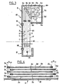
- Figure 1 shows the flexible support receiving one of the posters.
- This support is formed of a flexible primer band 1, such as a thin waxed cloth, which is wound on a rotary cylindrical drum 5, of horizontal axis 50.
- the latter is parallel to the general vertical plane, containing the viewing window, not shown.
- the band 1 passes over a cylindrical return roller 6, of horizontal axis parallel to that of the drum 5.
- the return is approximately at right angles, the band portion connecting the roller 6 to the drum 5 is therefore approximately horizontal
- flanges 60 At each end of the roll 6 are provided flanges 60 forming stops for the lateral edges of the strip. These flanges 60 have a conical wall, which converges inward, so as to promote the proper centering of the band, both when it is unwound and when it is wound.
- the free end of the band 1 has a border zone 10 for receiving and holding the upper edge 40 of a poster 4, this easily removable.
- the poster is made of a usual material, thin and flexible, but mechanically resistant and hardly crumplable, such as strong paper, a film of plastic or fabric for example. It carries a message M, for example printed, so centered and dimensioned that it is intended to be entirely visible through the viewing window (not shown in FIG. 1), whose dimensions are a little smaller than those of FIG. poster.
- the hooking is done by a fastening system with gripping tissues, loops and hooks, of the type widely distributed under the trade name "VELCRO" (registered trademark).
- the transverse end edge 10 of the primer strip 1 carries, on its face opposite to that facing the viewing window, one of the two elements of the gripping fabric 10A, for example the hooks.
- each poster 4 is lined, in its upper edge zone 40, with the other element of the gripping fabric 40A - in this case the loops -.
- the lower edge 41 of the poster consists of a hem, or sleeve, made by folding, then gluing or sewing, its lower end portion.
- ballast bar 2 forming a counterweight.
- This is for example a metal bar of rectangular or square section; its length is slightly larger than the width of the poster, so that its end portions 20, 20 'protrude on each side of the sheath
- the weight of the bar 2 must be sufficient to correctly stretch the poster in the vertical direction, while it is attached to the primer strip; if necessary additional weights, tubular shape can be nested on the bar, particularly at its ends. Nevertheless, the bar must not be excessively heavy so as not to upset the action of the motor during winding, ie the raising of the poster; otherwise it would be necessary to make use of excessively powerful engines.
- the band 1 wraps almost completely on the drum, while the bar 2 comes to occupy a high position, above the level of the viewing window.
- the poster is therefore in a retracted position, folded over the return roller 6.
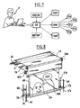
- Figure 3 shows how are installed in the device a set of five poster supports such as that just described.
- the viewing window which comprises a frame 91 and a transparent panel 90 disposed vertically, for example a window.
- the device comprises a frame 8, consisting essentially of a front wall 82, in which the window 9 is mounted, a top box 80 and a bottom box 81.
- the lower box 81 is open upwards; it receives and shelters looks the lower part of an unfolded poster.
- the various posters in the deployed position are in vertical planes a, b, c, d, e, parallel to the window 90. These different planes are spaced regularly, separated from each other. a weak space j. Similarly, the plan of the first poster (the poster closest to the window) is located at a short distance k from the window 90.
- the locations of the different return rollers 6a, 6b, 6c, 6d and 6e, and of the various drums 5a, 5b, 5c, 5d and 5e, inside the box 80, are determined so as to have the largest space requirement. possible, with no risk of contact between the posters and posters.
- These members comprise a pair of sliders 7, 7 'carried by the ends 20 and 20' respectively of the ballast bar 2. Said sliders are able to move in translation along vertical rods 3, 3 ', arranged laterally, respectively. outside the frame of the viewing window.
- the slider 7 is a U-shaped stirrup (for example a U-shaped flat iron) whose semicylindrical base surrounds the rod 3.
- the latter is for example metallic, too. It has a circular section of diameter slightly smaller than the width of the "U" yoke 7, so as to achieve good guidance, without friction, thereof.
- the part 7 is fixed to the bar portion 20 in easily removable manner.
- the spacing of the two cheeks 72 constituting the branches of the "U" corresponds to the thickness of the bar 2.
- the portion 20 is traversed by a pair of transverse holes 21.
- the cheeks 72 are pierced by openings 70 intended to come in correspondence with the latter when the stirrup 7 is to cap the end of the bar.
- the openings 70 are tapped holes, allowing attachment by means of screws 710.
- the rods 3, 3 ' are fixed by their upper and lower ends to the boxes 80, respectively 81, by appropriate means, not shown.
- Each poster is thus associated with a pair of lateral guide rods 3, 3 '.
- the weight bar is always perfectly horizontal.
- the rod being trapped inside the caliper, the risk of untimely escape of the caliper is zero, even if the device is exposed to sudden movements, as can happen when teaming a vehicle .
- the poster to be replaced is deployed (bar 2 in the down position).
- stirrups 7, 7 ' are disassembled, which allows to unmount the weight bar 2 out of the hem 41. Finally, the upper zone 40 is detached from the hooking edge 10 of the primer strip.
- the introduction of the new poster is done by the reverse operations: fixing the upper edge against the bank 10; fitting of the bar 2 in the hem 41; fixing stirrups 7, 7 '(previously put in place around the rods 3, 3') at the ends of the bar 2.
- the rods 3, 3 ' are advantageously arranged in staggered rows on each side of the device, as seen in FIG. 4.
- Each rod is shifted transversely by a certain amount. distance "m” relative to the rod (s) nearby (s). This prevents the stirrups 7 or 7 'of two adjacent bars are too close to each other.
- FIG. 6 represents an optoelectronic detection system, for example with photocells, mounted at the base of the device, on one of its sides. It comprises a transmitter 200 and a receivers 201 of known types, whose radiation line, referenced 2000, extends horizontally, transversely to the plane of the posters. It is next to one of the end portions 20 of the set of weight bars 2. When a poster reaches the end of the deployment stroke (low position), the line 2000 is thus cut off, activating the detection system which sends a signal corresponding to this information to the central control unit.
- This system makes it possible to detect anomalies, in particular in the event of a jamming of a poster against an obstacle, of a breakdown or of an unexpected blocking of a drum.
- the central unit can then perform an ad hoc command, for example trigger an alarm or light a light.
- a similar detection system is advantageously provided in the upper part of the device, or in an intermediate zone at half height.
- Figure 6 is shown in broken lines a high position detector system, comprising elements 200'-201 'and a line of sight 2000' similar to those used to detect the low position.
- each drum 5 is performed by an electric gear motor 51 fixed to the frame 8, and whose output shaft coaxially drives the shaft 50 of the drum.
- All five motors driving the drums 5a to 5d is controlled by a microcomputer or a programmable controller.
- It comprises a central unit 100, in which an operator P has introduced, using a keyboard, the various data related to the desired display cycle, in particular the scroll and exposure order, the frequency and exposure time of each poster (see Figure 7).
- the central unit drives the motors via a relay card, or interface, 1000.
- Some posters may of course be displayed longer and / or more frequently than others, depending on the program.
- substitution of a poster by another can be done in an extremely short time, since the retraction of the previous poster and the deployment of the new poster can be done simultaneously, in hidden time.
- the poster 4A has a window 400 which shows the poster 4B located behind it. This is a simple opening through the poster, or a transparent area. Thus, depending on the degree of winding of the band 1B which carries the poster 4B placed behind the poster 4A, these are different areas of this poster which will be visible at through the said window 400. Consequently, if one affixes on the poster poster different drawings, messages or other inscriptions, able to come selectively opposite the window 400, the displayed scene, visible on the screen, can be modified in an evolutionary manner. previous poster.
- the window is a "bubble" representative of the reflection of an advertising character.
- messages may also be displayed on one (or more) poster (s) farther away (s) which become (s) visible (s) when the poster (s) intercalated (s) between ( s) and the previous poster is (are) fully read (s).
- the device lends itself remarkably to progressive advertising campaigns in which a poster carries a message announcing information to be discovered on one or more poster (s) following (s).
- Poster hanging systems at their upper edge other than "gripping" fabrics can of course be provided, for example a fastening by clamps, snap-fastener type, adhesive tapes or a system of the type known under the trade name "ZIP" (registered trademark), comprising a plastic tongue engaging in a complementary groove.
- ZIP trade name
- a viewing window 4 can be open, or having a window 90 easily removable.
- the dimensions of the device are adapted to the dimensions of the posters concerned.
- the width of the band 1 is between 1 m and a few meters, the drums 5 and the return rollers 6 having a suitable length.
- the drums 5 may be aluminum, with a diameter of the order of 60 mm.
- rollers 6 are preferably surface-treated aluminum, so as not to leave marks on the back of the posters; their diameter will be of the order of 30 to 40 mm.
- the spacing between posters j is of the order of 15 to 30 mm.
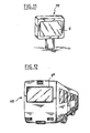
- This kind of device can be used in a fixed location, for example integrated in the facade of a building, or housed in a panel mounted on a foot or other support, such as the advertising panel PP shown in Figure 11.
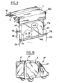
- This figure shows a vehicle of the van type, whose body has approximately the shape of a rectangular parallelepiped.
- This box has two lateral faces and a rear wall, each provided with a viewing window 9-9 ', respectively 9 ", posters.
- the display devices according to the invention are installed at inside the vehicle and each associated with one of the windows.
- the central unit can control not only the display sequencing of the various posters associated with a window, but of all three groups of posters.
- Each group may have different or identical posters, in whole or in part.
- a fourth viewing window may be provided. This can advantageously be installed above the driver's cab, for example integrated in the nasturtium, referenced CP in Figure 10; it is thus visible from the front.
- the vehicle can also serve as an exhibition showcase for products contained in the box, which become visible through one or more windows, since all the posters in this window are identified. Appropriate lighting may be provided inside the box to highlight the items on display.
- FIG. 12 shows, seen from the rear, a bus AB equipped with a display device according to the invention.
- the viewing window 9 '' ' is disposed in the rear face of the bus.
- said window 9 '' ' is dimensioned and positioned to occupy only the upper half of the rear face of the vehicle.
- stirrups 7, 7 'could be replaced by rings encircling the guiding bars (or cables) and removably adaptable to the ends of the weighting bar.
Landscapes
- Physics & Mathematics (AREA)
- General Physics & Mathematics (AREA)
- Engineering & Computer Science (AREA)
- Theoretical Computer Science (AREA)
- Displays For Variable Information Using Movable Means (AREA)
- Vehicle Waterproofing, Decoration, And Sanitation Devices (AREA)
Claims (11)
- Vorrichtung zum einzelnen, selektiven Anzeigen verschiedener Anzeigen einer Gesamtheit, indem sie nacheinander hinter einem Visualisierungsfenster (9) positioniert werden, bei der jede der Anzeigen (4) an ihrem oberen Rand (40) entfernbar an einem nachgiebigem Vorspannband (1) befestigt ist, das geeignet ist, wenigstens teilweise auf einer Aufnahmedrehtrommel (5) aufgewickelt zu werden, wobei diese Vorrichtung eine Reihe elektrischer Getriebemotoren (51) umfasst, die von einer programmierbaren Zentraleinheit (100) gesteuert werden und jeder ausgelegt ist, die eine der Trommeln (5) wahlweise in eine Richtung oder eine andere anzutreiben, um die Anzeige (4) entweder in eine eingefahrene Position, in der sie nicht hinter dem Visualisierungsfenster (9) erscheint, oder in eine ausgefahrene Position, in der sie sich gegenüber dem Fenster (9) befindet, bringen zu können, wobei die ausgefahrenen Positionen der verschiedenen Anzeigen (4) in verschiedene vertikale, parallele Ebenen (a, b, c, d, e) einbeschrieben sind, die leicht voneinander beabstandet sind, dadurch gekennzeichnet, dass der untere Rand jeder der Anzeigen aus einen Saum (41) besteht, der als Hülse dient, in den eine horizontale Beschwerungsstange (2) eingeführt ist, die das Unterspannungsstellen der Anzeige (4) sicherstellt, wobei die beiden Enden (20,20') dieser Stange (2) aus der Hülse auf jeder Seite der Anzeige (4) hervorstehen und wobei jede mit einem abnehmbaren Schieber (7) in Ring- oder Halbringform ausgestattet ist, der mit einem gewissen Spiel eine vertikale Führung (3) umgibt.
- Vorrichtung gemäß Anspruch 1, dadurch gekennzeichnet, dass jeder der Schieber aus einem Bügel besteht, der von oben betrachtet die allgemeine Form eines "U" aufweist, dessen Boden (71) den Führungsstab (3) umgibt, während seine Seitenarme (72) das Ende (20) der Stange umspannen und an jener durch abnehmbare Verbindungsmittel, wie beispielsweise Schrauben (71), befestigt sind.
- Vorrichtung gemäß Anspruch 1 oder 2, dadurch gekennzeichnet, dass auf jeder Seite der Vorrichtung die Führungsstäbe (3) abwechselnd zueinander um einen gegebenen Abstand "m" seitlich versetzt sind, was ihnen von oben betrachtet eine versetzte Anordnung verleiht.
- Vorrichtung gemäß einem der Ansprüche 1 bis 3, dadurch gekennzeichnet, dass sie Mittel zur Steuerung des Ausfahrens der Anzeigen (4) der Gesamtheit umfasst.
- Vorrichtung gemäß Anspruch 4, dadurch gekennzeichnet, dass die Steuermittel wenigstens eine optoelektronische Vorrichtung (200, 201) umfassen, deren Detektierungslinie (2000) sich horizontal auf der einen der Seiten der Anzeigengesamtheit (4) senkrecht zu ihrer Ausfahrebene in einer Position derart erstreckt, dass diese Linie (2000) geeignet ist, von dem einen der Enden (20) jeder Beschwerungsstange (2) während der Aufwärts- oder Abwärtsbewegung dieser Stange geschnitten zu werden.
- Vorrichtung gemäß Anspruch 5, dadurch gekennzeichnet, dass die Detektierungslinie (2000,2000') sich an der Basis und/oder am oberen Teil der Vorrichtung erstreckt und ausgelegt ist, die Ankunft in tiefer Position zu überprüfen, das heißt am Ende ihres Ausfahrverlaufs, und/oder in hoher Position, das heißt am Ende des Rückzugverlaufs wenigstens einer Anzeige (4).
- Werbefahrzeug (VP), welches mit wenigstens einer Vorrichtung gemäß einem der vorhergehenden Ansprüche ausgestattet ist.
- Werbefahrzeug (VP) gemäß Anspruch 7, dadurch gekennzeichnet, dass es mehrere Vorrichtungen und entsprechend mehrere Visualisierungsfenster (9,9') umfasst, wobei diese verschiedenen Vorrichtungen von einer gemeinsamen, zentralen Programmiereinheit (100) aus gesteuert werden.
- Werbefahrzeug (VP) gemäß Anspruch 8, dadurch gekennzeichnet, dass es aus einem Kleintransporter besteht, dessen Karosserie die allgemeine Form eines Quaders hat und dieser drei Visualisierungsfenster umfasst, von denen zwei (9,9') auf seinen Seitenwänden gelegen sind und das andere (9") auf seiner Rückwand, wobei die gemeinsame Zentraleinheit (100) geeignet ist, derart programmiert zu werden, dass dieselbe Werbenachricht (M) gleichzeitig auf wenigstens zwei dieser Fenster angezeigt wird.
- Fahrzeug für den Transport von Reisenden, insbesondere ein Autobus (AB), das mit wenigstens einer Vorrichtung gemäß einem der Ansprüche 1 bis 6 ausgestattet ist und dessen Visualisierungsfenster (9''') in der Rückwand des Fahrzeugs angeordnet ist.
- Ortsfestes Werbeplakat (PP), das mit wenigstens einer Vorrichtung gemäß einem der Ansprüche 1 bis 6 ausgestattet ist.
Applications Claiming Priority (3)
| Application Number | Priority Date | Filing Date | Title |
|---|---|---|---|
| FR0103058A FR2821969B1 (fr) | 2001-03-06 | 2001-03-06 | Dispositif d'affichage selectif d'affiches |
| FR0103058 | 2001-03-06 | ||
| PCT/FR2002/000801 WO2002071375A2 (fr) | 2001-03-06 | 2002-03-06 | Dispositif d'affichage selectif d'affiches |
Publications (2)
| Publication Number | Publication Date |
|---|---|
| EP1366483A2 EP1366483A2 (de) | 2003-12-03 |
| EP1366483B1 true EP1366483B1 (de) | 2008-01-23 |
Family
ID=8860810
Family Applications (1)
| Application Number | Title | Priority Date | Filing Date |
|---|---|---|---|
| EP02714282A Expired - Lifetime EP1366483B1 (de) | 2001-03-06 | 2002-03-06 | Vorrichtung zur selektiven anzeige von anzeigen |
Country Status (7)
| Country | Link |
|---|---|
| EP (1) | EP1366483B1 (de) |
| CN (1) | CN1201276C (de) |
| AU (1) | AU2002246200A1 (de) |
| BG (1) | BG64915B1 (de) |
| FR (1) | FR2821969B1 (de) |
| RU (1) | RU2003129511A (de) |
| WO (1) | WO2002071375A2 (de) |
Families Citing this family (6)
| Publication number | Priority date | Publication date | Assignee | Title |
|---|---|---|---|---|
| US9251577B2 (en) * | 2011-03-04 | 2016-02-02 | The University Of Tokushima | Information providing method and information providing device |
| CN102944966B (zh) * | 2012-10-17 | 2014-02-12 | 廖长春 | 交互式投影幕 |
| CN108584747A (zh) * | 2018-05-17 | 2018-09-28 | 广州市创视智能设备有限公司 | 一种电动投影幕的钢丝重叠卷线器 |
| CN109064931A (zh) * | 2018-08-02 | 2018-12-21 | 安徽本质智能科技有限公司 | 防水雾广告灯箱 |
| CN109064930A (zh) * | 2018-08-02 | 2018-12-21 | 安徽本质智能科技有限公司 | 便民式广告灯箱 |
| CN113066400B (zh) * | 2021-03-29 | 2022-03-01 | 江苏金牛星电子科技有限公司 | 一种滚动频率可调节的户外灯箱用滚动系统 |
Family Cites Families (6)
| Publication number | Priority date | Publication date | Assignee | Title |
|---|---|---|---|---|
| DE344417C (de) * | 1919-07-31 | 1921-11-22 | Oskar Widmer | Stellvorrichtung fuer Rollvorhaenge mit ringartig die Fuehrungsstangen umgreifenden Sperrhebeln |
| US4089361A (en) * | 1976-08-24 | 1978-05-16 | Heinz Zeppmeisel | Reel apparatus for background sheet |
| GB2046334A (en) * | 1979-03-07 | 1980-11-12 | Hall & Co Ltd G | Light-excluding mountings for roller blinds |
| FR2696034B1 (fr) * | 1992-09-24 | 1994-11-10 | Decaux Jc | Procédé et appareillage de visualisation sélective d'un message inscrit sur une bande support de messages. |
| FR2722903B1 (fr) * | 1994-07-20 | 1996-10-04 | Mobil Affiche | Dispositif d'affichage individuel et selectif d'un ensemble d'affiches |
| DE29820914U1 (de) * | 1998-11-23 | 1999-01-28 | Clauss Markisen Projekt GmbH, 73266 Bissingen | Senkrechtmarkise |
-
2001
- 2001-03-06 FR FR0103058A patent/FR2821969B1/fr not_active Expired - Fee Related
- 2001-09-27 BG BG105960A patent/BG64915B1/bg unknown
-
2002
- 2002-03-06 EP EP02714282A patent/EP1366483B1/de not_active Expired - Lifetime
- 2002-03-06 CN CN 02801514 patent/CN1201276C/zh not_active Expired - Fee Related
- 2002-03-06 RU RU2003129511/12A patent/RU2003129511A/ru not_active Application Discontinuation
- 2002-03-06 WO PCT/FR2002/000801 patent/WO2002071375A2/fr not_active Ceased
- 2002-03-06 AU AU2002246200A patent/AU2002246200A1/en not_active Abandoned
Also Published As
| Publication number | Publication date |
|---|---|
| FR2821969A1 (fr) | 2002-09-13 |
| AU2002246200A1 (en) | 2002-09-19 |
| CN1201276C (zh) | 2005-05-11 |
| WO2002071375A3 (fr) | 2003-02-20 |
| BG105960A (en) | 2002-09-30 |
| WO2002071375A2 (fr) | 2002-09-12 |
| RU2003129511A (ru) | 2005-04-10 |
| BG64915B1 (bg) | 2006-08-31 |
| CN1462421A (zh) | 2003-12-17 |
| FR2821969B1 (fr) | 2003-12-19 |
| EP1366483A2 (de) | 2003-12-03 |
Similar Documents
| Publication | Publication Date | Title |
|---|---|---|
| CA2195478C (fr) | Dispositif d'affichage individuel et selectif d'un ensemble d'affiches | |
| FR2804533A1 (fr) | Dispositif d'affichage a panneau deroulant | |
| EP1366483A2 (de) | Vorrichtung zur selektiven anzeige von anzeigen | |
| EP0459921B1 (de) | Anzeigevorrichtung | |
| EP0179499A2 (de) | Abnehmbares Reklameschild für Container und ähnliche Transportmittel | |
| FR2680424A1 (fr) | Dispositif pour l'affichage alternatif de decors. | |
| EP1836533B1 (de) | Zusammenklappbarer projektionsschirm, bestehend aus einem in einer box hinter einer wanddekoration zurückgezogenen reflektierenden stoff | |
| EP0740824B1 (de) | Vorrichtung zur selektiven anzeige von informationen | |
| EP0765515B1 (de) | Autonomes, gesteuertes modul zum lagern, auswaehlen und praesentieren von anzeigen | |
| WO2010063903A1 (fr) | Dispostif d'affichage deroulant autoporte a visualisation optimale | |
| EP1624430A2 (de) | Anzeigevorrichtung | |
| FR2735602A1 (fr) | Procede et dispositif d'affichage dynamique d'informations | |
| BE1027528B1 (fr) | Dispositif pour présentation d'objet | |
| FR2886334A1 (fr) | Porte a rideau souple | |
| EP0613113B1 (de) | Anzeigevorrichtung für mehrfache Anzeigen | |
| FR2925743A1 (fr) | Procede et dispositif d'affichage | |
| FR2608302A1 (fr) | Dispositif de presentation d'informations, plus particulierement pour magasin a grande surface | |
| FR2878364A1 (fr) | Dispositif d'affichage permettant le defilement d'une banniere d'affiches le long d'un support | |
| FR2639887A1 (fr) | Caisse de chargement a rideaux pour vehicule de transport routier et vehicule pourvu d'une telle caisse | |
| WO2012015289A2 (fr) | Dispositif d ' affichage a defilement selectif d'un ensemble d'affiches | |
| CA2318324C (fr) | Dispositif d'affichage sequentiel permettant la fixation individuelle de plusieurs affiches sur un film support | |
| FR2792099A1 (fr) | Dispositif d'affichage dynamique oscillant | |
| FR2899370A1 (fr) | Procede d'affichage d'informations, en particulier d'informations publicitaires ainsi que support publicitaire permettant la mise en oeuvre de ce procede | |
| FR2943715A1 (fr) | Ensemble de store notamment pour hublot d'aeronef, comprenant des moyens de maintien en tension | |
| EP0276590A1 (de) | Hängendes Schild |
Legal Events
| Date | Code | Title | Description |
|---|---|---|---|
| PUAI | Public reference made under article 153(3) epc to a published international application that has entered the european phase |
Free format text: ORIGINAL CODE: 0009012 |
|
| AK | Designated contracting states |
Kind code of ref document: A2 Designated state(s): AT BE CH CY DE DK ES FI FR GB GR IE IT LI LU MC NL PT SE TR |
|
| AX | Request for extension of the european patent |
Extension state: AL LT LV MK RO SI |
|
| 17P | Request for examination filed |
Effective date: 20031001 |
|
| GRAP | Despatch of communication of intention to grant a patent |
Free format text: ORIGINAL CODE: EPIDOSNIGR1 |
|
| RAP1 | Party data changed (applicant data changed or rights of an application transferred) |
Owner name: SOFIREM SOCIETE PAR ACTIONS SIMPLIFIEE |
|
| RBV | Designated contracting states (corrected) |
Designated state(s): FR |
|
| REG | Reference to a national code |
Ref country code: DE Ref legal event code: 8566 |
|
| GRAS | Grant fee paid |
Free format text: ORIGINAL CODE: EPIDOSNIGR3 |
|
| GRAA | (expected) grant |
Free format text: ORIGINAL CODE: 0009210 |
|
| AK | Designated contracting states |
Kind code of ref document: B1 Designated state(s): FR |
|
| AX | Request for extension of the european patent |
Extension state: RO |
|
| PLBE | No opposition filed within time limit |
Free format text: ORIGINAL CODE: 0009261 |
|
| STAA | Information on the status of an ep patent application or granted ep patent |
Free format text: STATUS: NO OPPOSITION FILED WITHIN TIME LIMIT |
|
| 26N | No opposition filed |
Effective date: 20081024 |
|
| PGFP | Annual fee paid to national office [announced via postgrant information from national office to epo] |
Ref country code: FR Payment date: 20130402 Year of fee payment: 12 |
|
| REG | Reference to a national code |
Ref country code: FR Ref legal event code: ST Effective date: 20141128 |
|
| PG25 | Lapsed in a contracting state [announced via postgrant information from national office to epo] |
Ref country code: FR Free format text: LAPSE BECAUSE OF NON-PAYMENT OF DUE FEES Effective date: 20140331 |