EP1364849A2 - Druckbegrenzungseinrichtung und Verfahren zum Entlasten einer Druckbegrenzungseinrichtung - Google Patents
Druckbegrenzungseinrichtung und Verfahren zum Entlasten einer Druckbegrenzungseinrichtung Download PDFInfo
- Publication number
- EP1364849A2 EP1364849A2 EP03011113A EP03011113A EP1364849A2 EP 1364849 A2 EP1364849 A2 EP 1364849A2 EP 03011113 A EP03011113 A EP 03011113A EP 03011113 A EP03011113 A EP 03011113A EP 1364849 A2 EP1364849 A2 EP 1364849A2
- Authority
- EP
- European Patent Office
- Prior art keywords
- pressure
- piston
- outlet
- limiting device
- pressure relief
- Prior art date
- Legal status (The legal status is an assumption and is not a legal conclusion. Google has not performed a legal analysis and makes no representation as to the accuracy of the status listed.)
- Withdrawn
Links
- 238000000034 method Methods 0.000 title claims description 27
- 238000007789 sealing Methods 0.000 claims description 17
- 230000008569 process Effects 0.000 claims description 13
- 238000013022 venting Methods 0.000 claims description 12
- 238000006073 displacement reaction Methods 0.000 claims description 5
- 239000007787 solid Substances 0.000 claims description 3
- 230000000694 effects Effects 0.000 description 6
- 238000010276 construction Methods 0.000 description 5
- 238000011161 development Methods 0.000 description 4
- 230000018109 developmental process Effects 0.000 description 4
- 239000011248 coating agent Substances 0.000 description 3
- 238000000576 coating method Methods 0.000 description 3
- 238000009423 ventilation Methods 0.000 description 3
- 230000008901 benefit Effects 0.000 description 2
- 230000001419 dependent effect Effects 0.000 description 2
- 238000010586 diagram Methods 0.000 description 2
- 210000003746 feather Anatomy 0.000 description 2
- 230000003993 interaction Effects 0.000 description 2
- 230000001681 protective effect Effects 0.000 description 2
- 230000009467 reduction Effects 0.000 description 2
- 241001295925 Gegenes Species 0.000 description 1
- 230000002950 deficient Effects 0.000 description 1
- 238000013461 design Methods 0.000 description 1
- 238000011982 device technology Methods 0.000 description 1
- 238000010438 heat treatment Methods 0.000 description 1
- 238000004519 manufacturing process Methods 0.000 description 1
- 238000012986 modification Methods 0.000 description 1
- 230000004048 modification Effects 0.000 description 1
- 230000035515 penetration Effects 0.000 description 1
- 239000000126 substance Substances 0.000 description 1
- 238000004078 waterproofing Methods 0.000 description 1
Images


Classifications
-
- B—PERFORMING OPERATIONS; TRANSPORTING
- B60—VEHICLES IN GENERAL
- B60T—VEHICLE BRAKE CONTROL SYSTEMS OR PARTS THEREOF; BRAKE CONTROL SYSTEMS OR PARTS THEREOF, IN GENERAL; ARRANGEMENT OF BRAKING ELEMENTS ON VEHICLES IN GENERAL; PORTABLE DEVICES FOR PREVENTING UNWANTED MOVEMENT OF VEHICLES; VEHICLE MODIFICATIONS TO FACILITATE COOLING OF BRAKES
- B60T17/00—Component parts, details, or accessories of power brake systems not covered by groups B60T8/00, B60T13/00 or B60T15/00, or presenting other characteristic features
- B60T17/18—Safety devices; Monitoring
-
- B—PERFORMING OPERATIONS; TRANSPORTING
- B60—VEHICLES IN GENERAL
- B60T—VEHICLE BRAKE CONTROL SYSTEMS OR PARTS THEREOF; BRAKE CONTROL SYSTEMS OR PARTS THEREOF, IN GENERAL; ARRANGEMENT OF BRAKING ELEMENTS ON VEHICLES IN GENERAL; PORTABLE DEVICES FOR PREVENTING UNWANTED MOVEMENT OF VEHICLES; VEHICLE MODIFICATIONS TO FACILITATE COOLING OF BRAKES
- B60T11/00—Transmitting braking action from initiating means to ultimate brake actuator without power assistance or drive or where such assistance or drive is irrelevant
- B60T11/10—Transmitting braking action from initiating means to ultimate brake actuator without power assistance or drive or where such assistance or drive is irrelevant transmitting by fluid means, e.g. hydraulic
- B60T11/28—Valves specially adapted therefor
- B60T11/34—Pressure reducing or limiting valves
-
- G—PHYSICS
- G05—CONTROLLING; REGULATING
- G05D—SYSTEMS FOR CONTROLLING OR REGULATING NON-ELECTRIC VARIABLES
- G05D16/00—Control of fluid pressure
- G05D16/04—Control of fluid pressure without auxiliary power
- G05D16/10—Control of fluid pressure without auxiliary power the sensing element being a piston or plunger
- G05D16/107—Control of fluid pressure without auxiliary power the sensing element being a piston or plunger with a spring-loaded piston in combination with a spring-loaded slideable obturator that move together over range of motion during normal operation
Definitions
- the invention relates to a pressure limiting device with an inlet which can be connected to means for generating pressure, one connectable to at least one pressure consumer Outlet, a movable piston which is dependent from a pressure at the outlet to different Positions is convertible, an intake valve that connects the inlet to the outlet in a first state and in a second state the inlet against the Outlet seals, the inlet valve depending from the position of the piston to the first state and in the second state is convertible, and a sealable Pressure relief connection sealed in a Condition the outlet seals against a pressure relief chamber and the outlet in an unsealed condition connects to the pressure relief chamber, the sealable Pressure relief connection depending on the position of the piston in the sealed state and is convertible into the unsealed state, wherein the movable piston has a first active surface which by the pressure prevailing at the outlet with a first one Force is applied and has a second active surface, that of elastic means with a second force is applied, which counteracts the first force.
- the invention further relates to a method for relieving pressure a pressure limiting device.
- Generic pressure limiting devices come for example for pressure limitation in air brake systems of commercial vehicles or rail vehicles. They are used to print in one or more Pressure consumer circles to a maximum permissible Limit the pressure value, for example to a typical one 8.5 bar value.
- the pressure limiting device disclosed there includes an inlet valve through which a pressure source with a Pressure consumers can be connected. Reaches the Pressure on the consumer side a certain value that can be preset via a spring tension, so closes the inlet valve by the interaction of one Valve plates with a valve seat.
- the valve disk works continue with a hollow piston; this will an outlet valve is formed. Now rises in the closed Condition of the inlet valve the pressure in the area of the outlet the pressure limiting device above the permissible Limit value, the outlet valve opens by the Hollow piston lifts off the valve plate.
- the excess Pressure can be through the bore of the hollow piston in a Pressure relief chamber and from there via a throttle with constant Cross-section in a pressure relief chamber that means, for example, the atmosphere.
- a throttle with constant Cross-section in a pressure relief chamber that means, for example, the atmosphere.
- the pressure limiting device thus obtained has several Disadvantages.
- the outlet valve is opened by a Effective area of the hollow piston due to the pressure at the outlet the pressure limiting device with force is, whereby the hollow piston stands out from the valve plate. At that moment there is a flow from the outlet the pressure limiting device in the pressure reduction chamber. This has the consequence that a further active surface of the hollow piston now increased due to the in the pressure relief chamber existing pressure is applied with force. This force wants the piston back towards drive the valve disk. Ultimately, this force works the pressure relief function of the pressure limiting device opposite.
- the invention has for its object to overcome the disadvantages of the prior art and in particular to provide a pressure limiting device and a method for relieving a pressure limiting device, so that ultimately an inexpensive, fault-prone and comparatively small unit can be provided.
- the invention is based on the generic pressure limiting device in that the second effective area of the movable piston regardless of the condition of the sealable Pressure relief connection from the one at the outlet prevailing pressure is essentially unaffected. in the closed state of the exhaust valve becomes an effective area of the piston due to the prevailing at the outlet Pressurized with force, so that ultimately the sealable Pressure relief connection opens. It is also in the pressure relief device of the prior art the case. As soon as the sealable pressure relief connection opens, there are differences. At the State of the art opens the outlet valve so that a Force also on an opposing active surface Influences. At the pressure relief device this is different from the present invention.
- the sealable pressure relief connection through one with a housing wall of the pressure limiting device cooperating piston seal realized is, wherein at least one channel in the housing in non-sealing condition of the sealable pressure relief connection the outlet with the pressure relief chamber combines. There is therefore a pressure in the area of the outlet before that is below the limit pressure, so is the outlet not connected to the channel in the housing. If the However, pressure on, the piston seal evades the pressure moved so that ultimately the outlet with the Pressure relief chamber can be connected.
- this construction enables the direct connection of the Outlet with the pressure relief space, that is, without the Detour via a pressure relief chamber, counteracting dynamic pressures to avoid.
- the unsealed state the pressure relief connection several substates includes, so that the pressure relief connection depending the position of the piston different throttle cross sections having.
- the throttle cross section be adapted to the current pressure relief requirements.
- the different throttle cross sections realized by at least one channel are after moving the movable piston and can be released after. This also increases the throttle cross-section increases with increasing pressure, whereby however, with the increasing release of the channel one continuous pressure increase takes place.
- the different throttle cross sections are realized by at least one channel, the one with the displacement of the piston seal in the direction of sealing state to the non-sealing state anymore has a linearly increasing free cross section. you provides relief at the beginning, that is, at possibly comparatively low pressure, only a very small throttle cross section available. This avoids one excessive pressure drops, which subsequently returned would have to be balanced. However, if the Pressure is increasing, causing a further shift in the Piston seal leads, it can be useful a large To provide throttle cross-section, because now one rapid promotion of the print medium, that is, for example the air that is in the foreground.
- the pressure limiting device according to the invention is in further developed in a particularly useful manner in that the sealable pressure relief connection at least one Includes O-ring with the housing wall of the pressure limiting device interacts.
- This is a special one simple implementation of the sealable pressure relief connection, due to the use of standard components is in the sense of an inexpensive solution.
- the elastic means for loading the second active surface are realized with force as a spring.
- the inlet valve comprises a valve disk and a valve seat, wherein the valve plate is in the open state of the intake valve supported on the movable piston and in Spring loaded towards the valve seat becomes.
- the movable piston is massive is.
- pressure relief device technology was an essential element, that a hollow piston is provided. That was the only way State of the art a connection between the outlet and the pressure relief chamber and ultimately the pressure relief chamber to provide.
- no hollow piston needs to be provided because a direct connection due to the special arrangement between the outlet and the one leading to the pressure relief chamber Channel just by moving for example the piston seal can be made available.
- the effective area becomes for the pressure at the outlet of the pressure limiting device won.
- the pressure limiting device easier due to the use of a solid piston manufacture.
- the invention also consists in a method for relieving pressure a pressure limiting device, in particular one Pressure limiting device according to the present invention, which is characterized by a piston seal with a housing wall of the pressure limiting device interacts and depending on the position a pressure relief connection of the piston carrying the piston seal releases and that the pressure relief connection different depending on the position of the piston Throttle cross sections. So always a throttle cross section can be made available is adjusted to the prevailing pressure. That way the advantages and special effects of the invention Pressure limiting device also in the context of a Procedure realized. This also applies to the following specified particularly preferred embodiments and Developments of the method according to the invention.
- the method according to the invention is particularly special usefully trained so that the different Throttle cross sections through several channels in the housing are realized by the piston seal at Moving the movable piston successively be released so that a multi-stage venting process is present.
- the different throttle cross sections realized by at least one channel are after moving the movable piston and after being released so that a proportional or there is a disproportionate venting process.
- the different throttle cross sections by at least a channel are realized, one with the Displacement of the piston seal in the direction of the sealing State to non-sealing state more than linear has increasing free cross-section, so that a there is a disproportionate venting process.
- proportional and disproportionate venting process designated continuous ventilation processes also combined with the multi-stage venting process be, for example, by arranging several Channels that are gradually released, with additional at least one of the channels gradually released with proportionally or disproportionately growing free cross section.
- the invention is based on the knowledge that a Inexpensive and functional pressure relief device as well as one related in particular Method for relieving a pressure limiting device can be provided, the Disadvantages of the prior art eliminated and the problems of the prior art can be overcome.
- the pressure relief device is depressurized no counteraction on the pressure relief controlling piston instead, it is preferably not a hollow piston provided so that none of the cross section there is a reducing relief bore, it can be multi-stage and / or continuous, that is proportional or disproportionate ventilation processes are selected, so the problems due to excessive back pressure can be avoided and the number of sealing surfaces can be reduced are, for example, of three sealing surfaces in the described pressure limiting device State of the art are required on two sealing surfaces in the invention, namely the intake valve seat and the sealable pressure relief connection.
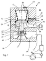
- FIG. 1 shows a schematic sectional view of a first Embodiment of a pressure limiting device according to the invention 10.
- the pressure limiting device shown 10 includes a housing 32 with an inlet 14 and an outlet 18. At the inlet is illustrative A reservoir 54 is connected via a line 52. The reservoir 54 is above a check valve 56 in connection with a compressor 12. At the Outlet 18 is illustrative of another Line 58 a container 16 connected to a pressure consumer symbolizes.
- the inlet 14 is shown in the Condition via an inlet valve 22, 24, 26 with the Outlet 18 in connection.
- the inlet valve 22, 24, 26 comprises a valve plate 22, which is covered with a sealing coating 26 can be based on a valve seat 24.
- Piston 20 On Piston 20 is supported in the state shown in Figure 1 via one or more ribs 60 on the valve plate 22 from.
- a piston seal On the opposite side of the ribs 60 of the Piston 20 is a piston seal arranged as with the housing wall 44 cooperating O-ring 34 is formed is.
- the piston 20 is at its opposite the ribs 60 Force applied to the end by a spring 42, which is supported on the housing 32.
- a pressure equalization room 62, in which the spring 42 is arranged, is via a vent hole 64 connected to the atmosphere 36.
- the Vent hole 64 is covered by a protective cap 66.
- the pressure compensation chamber 62 is shown in the State of the pressure limiting device 10 over two channels 28, 30 connected to the atmosphere 36.
- the Pressure compensation chamber 62 is created by the interaction of the O-rings 34 with the inner housing wall 44 against the outlet 18 sealed.
- the pressure limiting device 10 works as follows. In the depressurized state, the forces exerted by the springs 50 and 42 are coordinated with one another or can be coordinated with one another via pretensioning devices (not shown) such that the inlet 14 is connected to the outlet 18. Thus, a pressure generated by the compressor 12 can reach the outlet 18 via the inlet valve 22, 24, 26. With increasing pressure at the inlet 14, the pressure at the outlet 18 also rises, so that the force acting on the surface of the piston 20, which is referred to here as the first active surface 38, also increases. Because of the end-side construction of the piston 20 with ribs 60, the active surface 38 essentially corresponds to a circular surface with the diameter D 1 + D 2 , provided that the piston 20 is cylindrical.
- the ribs 60 also expose a significant area from the piston end surface that contributes to the active surface 38.
- the piston 20 is therefore driven upward with increasing pressure against the force of the spring 42 with respect to the illustration selected in FIG. 1, initially until the valve plate 22 with its sealing coating 26 is seated on the valve seat 24 and thus closes the inlet valve 22, 24, 26. Consequently, under normal conditions, there is no further increase in the pressure at the outlet 18, even when the pressure at the inlet 14 increases.
- the basic pressure-limiting function of the pressure-limiting device is therefore present. If, however, there is a further pressure increase at the outlet 18 for any reason, for example due to a leak in the inlet valve 22, 24, 26 or due to heating of the consumer 16, the piston 20 is driven further upwards.
- the piston 20 is then no longer supported on the valve plate 22.
- the O-ring 34 then releases the lower channel 28 in the housing 32, so that pressure relief can take place by the passage of air or another gaseous medium into the atmosphere 36, which acts as a pressure relief space.
- the piston 20 can be driven further upward, so that the upper channel 30 is also released after a further displacement distance. This leads to a lower throttling effect by increasing the relief cross section.
- the piston 20 moves downward again, so that compressed air can ultimately get from the inlet 14 to the outlet 18 again.
- the piston 20 only moves downwards to such an extent that the inlet valve 22, 24, 26 is not opening. In this case, the limit pressure is exactly at the outlet 18.
- the Pressure equalization chamber 62 is not used for pressure relief must become. It is therefore independent of the position of the Piston 20 has no force on the present second Effective area 40 designated area due to the at the outlet 18 existing pressure act. There is therefore no one Counteraction that drive the piston 20 down could and would be contrary to the relief process.
- FIG. 2 shows a schematic sectional view of a second Embodiment of a pressure limiting device according to the invention 10.
- FIG. 3 represents a detail relating to FIG. 2.
- the pressure limiting device 10 according to FIG. 2 only one channel 46 is provided, which the outlet 18 with the pressure relief space 36 or of the atmosphere.
- the Hole 64 equipped with a filter 68 which prevents penetration prevent substances from the atmosphere 36 can.
- Channel 46 is for providing a continuous Enlargement of the throttle cross-section when moving upwards of the piston 20 designed in a special way.
- the channel 46 in Figure 3 is in cross section shown.
- the line labeled 70 should be in the Figure 3 shown the bottom edge of the O-ring 34 symbolize. This position shown in Figure 3 O-rings 34 does not correspond to that shown in FIG. 2 Position of the O-ring 34.
- At 48 is the free flow cross section of the channel 46. Now the O-ring is moving 34 and thus the lower edge 40 further up, so the flow cross-section grows continuously and faster as linear with the displacement. Hence the Throttling effect of the channel 46 is quickly reduced, so that efficient pressure relief can take place.
- FIG. 4 shows a diagram in which the venting cross section is plotted against the pressure at the outlet of the pressure limiting device for different embodiments of the present invention.
- the cross section A of the relief opening develops, starting from the limit pressure P G , in different ways with increasing outlet pressure P A , depending on the design of the sealable pressure relief connection.
- Line a corresponds to a multi-stage pressure relief, which can take place, for example, in systems according to FIG. 1 with a plurality of channels 28, 30.
- Line b symbolizes a proportional pressure relief, which can be present, for example, when a ventilation channel is gradually released.
- Disproportionate pressure reliefs are also conceivable if the cross section of the channel is selected, for example, according to channel 46 according to FIG. 2 and FIG. 3.
Landscapes
- Engineering & Computer Science (AREA)
- Physics & Mathematics (AREA)
- Transportation (AREA)
- Mechanical Engineering (AREA)
- Fluid Mechanics (AREA)
- General Physics & Mathematics (AREA)
- Automation & Control Theory (AREA)
- Safety Valves (AREA)
Abstract
Description
- Figur 1
- eine schematische Schnittansicht einer ersten Ausführungsform einer erfindungsgemäßen Druckbegrenzungseinrichtung;
- Figur 2
- eine schematische Schnittansicht einer zweiten Ausführungsform einer erfindungsgemäßen Druckbegrenzungseinrichtung;
- Figur 3
- eine Einzelheit betreffend Figur 2; und
- Figur 4
- ein Diagramm, bei dem der Entlüftungsquerschnitt gegen den Druck am Auslass der Druckbegrenzungseinrichtung für unterschiedliche Ausführungsformen der vorliegenden Erfindung aufgetragen ist.
- 10
- Druckbegrenzungseinrichtung
- 12
- Kompressor
- 14
- Einlass
- 16
- Druckverbraucher
- 18
- Auslass
- 20
- Kolben
- 22
- Ventilteller
- 24
- Ventilsitz
- 26
- Dichtbeschichtung
- 28
- Kanal
- 30
- Kanal
- 32
- Gehäuse
- 34
- O-Ring
- 36
- Druckentlastungsraum
- 38
- Wirkfläche
- 40
- Wirkfläche
- 42
- Feder
- 44
- Gehäusewand
- 46
- Kanal
- 48
- Strömungsquerschnitt
- 50
- Feder
- 52
- Leitung
- 54
- Vorratsbehälter
- 56
- Rückschlagventil
- 58
- Leitung
- 60
- Rippe
- 62
- Druckausgleichsraum
- 64
- Entlüftungsbohrung
- 66
- Schutzkappe
- 68
- Filter
- 70
- Linie
- PG
- Grenzdruck
- PA
- Ausgangsdruck
- a
- mehrstufige Druckentlastung
- b
- proportionale Druckentlastung
- A
- Querschnitt der Entlastungsöffnung
Claims (16)
- Druckbegrenzungseinrichtung (10) mitdadurch gekennzeichnet, dass ein an die zweite Wirkfläche (40) des beweglichen Kolbens (20) angrenzender Raum (62) unabhängig von dem Zustand der abdichtbaren Druckentlastungsverbindung (28, 30, 34, 44, 46) gegen den Auslass (18) abgedichtet ist und eine Druckentlastung über einen Weg erfolgt, der den an die zweite Wirkfläche (40) des beweglichen Kolbens (20) angrenzenden Raum (62) nicht durchquert, so dass die zweite Wirkfläche (40) des beweglichen Kolbens (20) unabhängig von dem Zustand der abdichtbaren Druckentlastungsverbindung (28, 30, 34, 44, 46) von dem am Auslass (18) herrschenden Druck im Wesentlichen unbeeinflusst ist.einem mit Mitteln (12) zur Druckerzeugung verbindbaren Einlass (14),einem mit wenigstens einem Druckverbraucher (16) verbindbaren Auslass (18),einem beweglichen Kolben (20), der in Abhängigkeit von einem am Auslass (18) herrschenden Druck in verschiedene Positionen überführbar ist,einem Einlassventil (22, 24, 26), das in einem ersten Zustand den Einlass (14) mit dem Auslass (18) verbindet und in einem zweiten Zustand den Einlass (14) gegen den Auslass (18) abdichtet, wobei das Einlassventil (22, 24, 26) in Abhängigkeit von der Position des Kolbens (20) in den ersten Zustand und in den zweiten Zustand überführbar ist, undeiner abdichtbaren Druckentlastungsverbindung (28, 30, 34, 44, 46), die in einem abgedichteten Zustand den Auslass (18) gegen einen Druckentlastungsraum (36) abdichtet und in einem nicht abgedichteten Zustand den Auslass (18) mit dem Druckentlastungsraum (36) verbindet, wobei die abdichtbare Druckentlastungsverbindung (28, 30, 34, 44, 46) in Abhängigkeit von der Position des Kolbens (20) in den abgedichteten Zustand und in den nicht abgedichteten Zustand überführbar ist,wobei der bewegliche Kolben (20) eine erste Wirkfläche (38) aufweist, die durch den am Auslass (18) herrschenden Druck mit einer ersten Kraft beaufschlagt wird, und eine zweite Wirkfläche (40) aufweist, die von elastischen Mitteln (42) mit einer zweiten Kraft beaufschlagt wird, die der ersten Kraft entgegenwirkt,
- Druckbegrenzungseinrichtung nach Anspruch 1, dadurch gekennzeichnet, dass die abdichtbare Druckentlastungsverbindung (28, 30, 34, 44, 46) durch eine mit einer Gehäusewand (44) der Druckbegrenzungseinrichtung (10) zusammenwirkende Kolbendichtung (34) verwirklicht ist, wobei mindestens ein Kanal (28, 30, 46) in dem Gehäuse (32) im nicht abdichtenden Zustand der abdichtbaren Druckentlastungsverbindung (28, 30, 34, 44, 46) den Auslass (18) mit dem Druckentlastungsraum (36) verbindet.
- Druckbegrenzungseinrichtung nach Anspruch 1 oder 2, dadurch gekennzeichnet, dass der nicht abgedichtete Zustand der Druckentlastungsverbindung (28, 30, 34, 44, 46) mehrere Unterzustände umfasst, so dass die Druckentlastungsverbindung (28, 30, 34, 44, 46) in Abhängigkeit der Position des Kolbens (20) unterschiedliche Drosselquerschnitte aufweist.
- Druckbegrenzungseinrichtung nach Anspruch 3, dadurch gekennzeichnet, dass mit zunehmendem Druck am Auslass (18) der Drosselquerschnitt der Druckentlastungsverbindung (28, 30, 34, 44, 46) zunimmt.
- Druckbegrenzungseinrichtung nach Anspruch 3 oder 4, dadurch gekennzeichnet, dass die unterschiedlichen Drosselquerschnitte durch mehrere Kanäle (28, 30) in dem Gehäuse (32) realisiert sind, die von der Kolbendichtung beim Verschieben des beweglichen Kolbens (20) aufeinanderfolgend freigegeben werden können.
- Druckbegrenzungseinrichtung nach einem der Ansprüche 3 bis 5, dadurch gekennzeichnet, dass die unterschiedlichen Drosselquerschnitte durch mindestens einen Kanal (46) realisiert sind, der beim Verschieben des beweglichen Kolbens (20) nach und nach freigegeben werden kann.
- Druckbegrenzungseinrichtung nach einem der Ansprüche 3 bis 6, dadurch gekennzeichnet, dass die unterschiedlichen Drosselquerschnitte durch mindestens einen Kanal (46) realisiert sind, der einen mit dem Verschiebeweg der Kolbendichtung in Richtung vom abdichtenden Zustand zum nicht abdichtenden Zustand mehr als linear anwachsenden freien Querschnitt aufweist.
- Druckbegrenzungseinrichtung nach einem der vorangehenden Ansprüche, dadurch gekennzeichnet, dass die abdichtbare Druckentlastungsverbindung (28, 30, 34, 44, 46) mindestens einen O-Ring (34) umfasst, der mit der Gehäusewand (44) der Druckbegrenzungseinrichtung (10) zusammenwirkt.
- Druckbegrenzungseinrichtung nach einem der vorangehenden Ansprüche, dadurch gekennzeichnet, dass die elastischen Mittel zum Beaufschlagen der zweiten Wirkfläche (40) mit Kraft als Feder (42) realisiert sind.
- Druckbegrenzungseinrichtung nach einem der vorangehenden Ansprüche, dadurch gekennzeichnet, dass das Einlassventil (22, 24, 26) einen Ventilteller (22) und einen Ventilsitz (24) umfasst, wobeisich der Ventilteller (22) im geöffneten Zustand des Einlassventils (22, 24, 26) an dem beweglichen Kolben (20) abstützt undin Richtung auf den Ventilsitz (24) durch eine Feder (50) belastet wird.
- Druckbegrenzungseinrichtung nach einem der vorangehenden Ansprüche, dadurch gekennzeichnet, dass der bewegliche Kolben (20) massiv ist.
- Verfahren zum Entlasten einer Druckbegrenzungseinrichtung (10), insbesondere nach einem der vorangehenden Ansprüche, bei demdadurch gekennzeichnet,eine erste Wirkfläche eines beweglichen Kolbens (20) mit einer ersten Kraft beaufschlagt wird, die aus einem an einem Auslass (18) der Druckbegrenzungseinrichtung herrschenden Druck resultiert,der Kolben (20) infolge der ersten Kraft entgegen einer zweiten Kraft, die durch elastische Mittel (42) auf eine zweite Wirkfläche (40) des Kolbens (20) wirkt, verschoben wird undeine Kolbendichtung mit einer Gehäusewand (44) der Druckbegrenzungseinrichtung (10) zusammenwirkt und in Abhängigkeit der Position des die Kolbendichtung tragenden Kolbens (20) eine Druckentlastungsverbindung (28, 30, 34, 44, 46) freigegeben wird,dass ein an die zweite Wirkfläche (40) des beweglichen Kolbens (20) angrenzender Raum (62) unabhängig von der Stellung des Kolbens (20) gegen den Auslass (18) abgedichtet bleibt und eine Druckentlastung über einen Weg erfolgt, der den an die zweite Wirkfläche (40) des beweglichen Kolbens (20) angrenzenden Raum (62) nicht durchquert, so dass die zweite Wirkfläche (40) des beweglichen Kolbens (20) unabhängig von der Stellung des Kolbens von dem am Auslass (18) herrschenden Druck im Wesentlichen unbeeinflusst bleibt, unddass der Drosselquerschnitt der Druckentlastungsverbindung (28, 30, 34, 44, 46) in Abhängigkeit der Position des Kolbens (20) variiert wird.
- Verfahren nach Anspruch 12, dadurch gekennzeichnet, dass mit zunehmendem Druck am Auslass (18) der Druckbegrenzungseinrichtung (10) der Drosselquerschnitt der Druckentlastungsverbindung (28, 30, 34, 44, 46) zunimmt.
- Verfahren nach Anspruch 12 oder 13, dadurch gekennzeichnet, dass die unterschiedlichen Drosselquerschnitte durch mehrere Kanäle (28, 30) in dem Gehäuse (32) realisiert sind, die von der Kolbendichtung beim Verschieben des beweglichen Kolbens (20) aufeinanderfolgend freigegeben werden, so dass ein mehrstufiger Entlüftungsvorgang vorliegt.
- Verfahren nach einem der Ansprüche 12 oder 14, dadurch gekennzeichnet, dass die unterschiedlichen Drosselquerschnitte durch mindestens einen Kanal (46) realisiert sind, der beim Verschieben des beweglichen Kolbens (20) nach und nach freigegeben wird, so dass ein proportionaler oder überproportionaler Entlüftungsvorgang vorliegt.
- Verfahren nach einem der Ansprüche 12 oder 15, dadurch gekennzeichnet, dass die unterschiedlichen Drosselquerschnitte durch mindestens einen Kanal (46) realisiert sind, der einen mit dem Verschiebeweg der Kolbendichtung in Richtung vom abdichtenden Zustand zum nicht abdichtenden Zustand mehr als linear anwachsenden freien Querschnitt aufweist, so dass ein überproportionaler Entlüftungsvorgang vorliegt.
Applications Claiming Priority (2)
| Application Number | Priority Date | Filing Date | Title |
|---|---|---|---|
| DE10222903 | 2002-05-23 | ||
| DE10222903A DE10222903A1 (de) | 2002-05-23 | 2002-05-23 | Druckbegrenzungseinrichtung und Verfahren zum Entlasten einer Druckbegrenzungseinrichtung |
Publications (2)
| Publication Number | Publication Date |
|---|---|
| EP1364849A2 true EP1364849A2 (de) | 2003-11-26 |
| EP1364849A3 EP1364849A3 (de) | 2003-12-17 |
Family
ID=29285661
Family Applications (1)
| Application Number | Title | Priority Date | Filing Date |
|---|---|---|---|
| EP03011113A Withdrawn EP1364849A3 (de) | 2002-05-23 | 2003-05-22 | Druckbegrenzungseinrichtung und Verfahren zum Entlasten einer Druckbegrenzungseinrichtung |
Country Status (2)
| Country | Link |
|---|---|
| EP (1) | EP1364849A3 (de) |
| DE (1) | DE10222903A1 (de) |
Cited By (4)
| Publication number | Priority date | Publication date | Assignee | Title |
|---|---|---|---|---|
| DE102008053994A1 (de) * | 2008-10-30 | 2010-05-12 | Knorr-Bremse Systeme für Nutzfahrzeuge GmbH | Druckluftbegrenzungseinrichtung |
| CN104006192A (zh) * | 2013-02-26 | 2014-08-27 | 乔治洛德方法研究和开发液化空气有限公司 | 减压阀、设置有减压阀的龙头和瓶 |
| WO2018050400A1 (de) | 2016-09-19 | 2018-03-22 | Knorr-Bremse Systeme für Nutzfahrzeuge GmbH | Druckregelventil für ein luftaufbereitungssystem eines nutzfahrzeugs |
| CN108050259A (zh) * | 2018-01-17 | 2018-05-18 | 无锡市华科力士水液压有限公司 | 一种气动电比例调压装置 |
Family Cites Families (5)
| Publication number | Priority date | Publication date | Assignee | Title |
|---|---|---|---|---|
| US3559688A (en) * | 1965-06-04 | 1971-02-02 | Mack Trucks | Fluid pressure regulating valve |
| DE2922837A1 (de) * | 1979-06-06 | 1980-12-18 | Bosch Gmbh Robert | Druckbegrenzungsventil |
| DE3727317A1 (de) * | 1986-10-15 | 1988-04-28 | Berliner Bremsenwerk Veb | Fremdeinspeisung an hochdruckbremsanlagen, insbesondere fuer kraftfahrzeuge |
| DE4012576A1 (de) * | 1990-04-20 | 1991-10-24 | Bosch Gmbh Robert | Druckbegrenzungsventil mit einem sicherheitsventil |
| DE4344416A1 (de) * | 1993-12-24 | 1995-06-29 | Wabco Vermoegensverwaltung | Druckbegrenzungseinrichtung |
-
2002
- 2002-05-23 DE DE10222903A patent/DE10222903A1/de not_active Withdrawn
-
2003
- 2003-05-22 EP EP03011113A patent/EP1364849A3/de not_active Withdrawn
Cited By (8)
| Publication number | Priority date | Publication date | Assignee | Title |
|---|---|---|---|---|
| DE102008053994A1 (de) * | 2008-10-30 | 2010-05-12 | Knorr-Bremse Systeme für Nutzfahrzeuge GmbH | Druckluftbegrenzungseinrichtung |
| DE102008053994B4 (de) * | 2008-10-30 | 2015-10-29 | Knorr-Bremse Systeme für Nutzfahrzeuge GmbH | Druckluftbegrenzungseinrichtung |
| CN104006192A (zh) * | 2013-02-26 | 2014-08-27 | 乔治洛德方法研究和开发液化空气有限公司 | 减压阀、设置有减压阀的龙头和瓶 |
| US20140238508A1 (en) * | 2013-02-26 | 2014-08-28 | L'Air Liquide, Société Anonyme pour I'Etude I'Exploitation des Procédés Georges Claude | Pressure reducing valve, tap and bottle provided with such a pressure reducing valve |
| WO2018050400A1 (de) | 2016-09-19 | 2018-03-22 | Knorr-Bremse Systeme für Nutzfahrzeuge GmbH | Druckregelventil für ein luftaufbereitungssystem eines nutzfahrzeugs |
| DE102016117607A1 (de) | 2016-09-19 | 2018-03-22 | Knorr-Bremse Systeme für Nutzfahrzeuge GmbH | Druckregelventil für ein Luftaufbereitungssystem eines Nutzfahrzeugs |
| US10838438B2 (en) | 2016-09-19 | 2020-11-17 | Knorr-Bremse Systeme Fuer Nutzfahrzeuge Gmbh | Pressure regulating valve for an air supply system of a utility vehicle |
| CN108050259A (zh) * | 2018-01-17 | 2018-05-18 | 无锡市华科力士水液压有限公司 | 一种气动电比例调压装置 |
Also Published As
| Publication number | Publication date |
|---|---|
| DE10222903A1 (de) | 2003-12-11 |
| EP1364849A3 (de) | 2003-12-17 |
Similar Documents
| Publication | Publication Date | Title |
|---|---|---|
| DE2352742C2 (de) | Hydraulisches Senkbrems-Sperrventil | |
| DE4402647C1 (de) | Pneumatisch angesteuertes Gassicherheitsventil mit autonomer Druckluftversorgung | |
| DE2005592A1 (de) | Absperrorgan mit Druckausgleichseinrichtung | |
| EP3371019B1 (de) | Druckbegrenzungsventil | |
| WO2008080945A1 (de) | Drucksteuervorrichtung für ein fahrzeug | |
| EP1968835B1 (de) | Kombinierter betriebsbrems- und federspeicherbremszylinder mit innerer entlüftung | |
| EP1851098B9 (de) | Kombinierter federspeicher- und betriebsbremszylinder mit einer beatmungseinrichtung | |
| DE10251803A1 (de) | Kompressor | |
| DE4344416A1 (de) | Druckbegrenzungseinrichtung | |
| DE102013107826A1 (de) | Luftfeder für ein Kraftfahrzeug | |
| DE102009002003A1 (de) | Druckregelventil, insbesondere für ein Automatikgetriebe in einem Kraftfahrzeug | |
| DE3341643A1 (de) | Vorgesteuertes druckentlastungs- und steuerventil | |
| EP0289712B1 (de) | Druckregelventil | |
| DE10222903A1 (de) | Druckbegrenzungseinrichtung und Verfahren zum Entlasten einer Druckbegrenzungseinrichtung | |
| EP0922165B1 (de) | Vakuumpumpe | |
| EP0717201B1 (de) | Schutzsystem für eine Druckmittelanlage | |
| EP1018460B1 (de) | Mehrkreisschutzventil für Druckluftbeschaffungsanlagen von Kraftfahrzeugen | |
| DE2725153B2 (de) | Trägheitsgesteuerte Ventileinrichtung für ein hydraulisches Kraftfahrzeugbremssystem | |
| DE19755472C2 (de) | Gas-Druckregelgerät | |
| EP1346267B1 (de) | Überdruckerzeugungsvorrichtung | |
| DE19944808C1 (de) | Druckbegrenzungs- und Drucksicherungsventil für Druckluftbremsanlagen von Kraftfahrzeugen | |
| CH511386A (de) | Gasventil | |
| DE4400677A1 (de) | Entlastungsventil für ein Strebausbaugestell | |
| DE102014118270B3 (de) | Pneumatische Kupplung mit Lagervorspannung | |
| DE10357401B4 (de) | Entleerungsventil |
Legal Events
| Date | Code | Title | Description |
|---|---|---|---|
| PUAI | Public reference made under article 153(3) epc to a published international application that has entered the european phase |
Free format text: ORIGINAL CODE: 0009012 |
|
| PUAL | Search report despatched |
Free format text: ORIGINAL CODE: 0009013 |
|
| AK | Designated contracting states |
Kind code of ref document: A2 Designated state(s): AT BE BG CH CY CZ DE DK EE ES FI FR GB GR HU IE IT LI LU MC NL PT RO SE SI SK TR |
|
| AX | Request for extension of the european patent |
Extension state: AL LT LV MK |
|
| AK | Designated contracting states |
Kind code of ref document: A3 Designated state(s): AT BE BG CH CY CZ DE DK EE ES FI FR GB GR HU IE IT LI LU MC NL PT RO SE SI SK TR |
|
| AX | Request for extension of the european patent |
Extension state: AL LT LV MK |
|
| AKX | Designation fees paid | ||
| REG | Reference to a national code |
Ref country code: DE Ref legal event code: 8566 |
|
| STAA | Information on the status of an ep patent application or granted ep patent |
Free format text: STATUS: THE APPLICATION IS DEEMED TO BE WITHDRAWN |
|
| 18D | Application deemed to be withdrawn |
Effective date: 20040618 |