EP1363039B1 - Patin de frein à disque avec lèvre protectrice - Google Patents
Patin de frein à disque avec lèvre protectrice Download PDFInfo
- Publication number
- EP1363039B1 EP1363039B1 EP03009347A EP03009347A EP1363039B1 EP 1363039 B1 EP1363039 B1 EP 1363039B1 EP 03009347 A EP03009347 A EP 03009347A EP 03009347 A EP03009347 A EP 03009347A EP 1363039 B1 EP1363039 B1 EP 1363039B1
- Authority
- EP
- European Patent Office
- Prior art keywords
- brake
- brake pad
- disc
- friction lining
- lip
- Prior art date
- Legal status (The legal status is an assumption and is not a legal conclusion. Google has not performed a legal analysis and makes no representation as to the accuracy of the status listed.)
- Expired - Lifetime
Links
- 230000001681 protective effect Effects 0.000 title description 2
- 230000000694 effects Effects 0.000 claims description 4
- 229920001971 elastomer Polymers 0.000 claims description 4
- 239000005060 rubber Substances 0.000 claims description 3
- 239000013013 elastic material Substances 0.000 claims description 2
- 230000001012 protector Effects 0.000 claims 11
- 239000000463 material Substances 0.000 description 20
- 239000002245 particle Substances 0.000 description 9
- 239000000835 fiber Substances 0.000 description 6
- 239000007788 liquid Substances 0.000 description 6
- 238000004519 manufacturing process Methods 0.000 description 6
- 230000008901 benefit Effects 0.000 description 5
- 238000010276 construction Methods 0.000 description 5
- 229910052751 metal Inorganic materials 0.000 description 4
- 239000002184 metal Substances 0.000 description 4
- 229920001187 thermosetting polymer Polymers 0.000 description 4
- 238000011109 contamination Methods 0.000 description 3
- 238000001816 cooling Methods 0.000 description 3
- 238000009826 distribution Methods 0.000 description 3
- 239000000945 filler Substances 0.000 description 3
- 229910052500 inorganic mineral Inorganic materials 0.000 description 3
- 238000009413 insulation Methods 0.000 description 3
- 239000011707 mineral Substances 0.000 description 3
- XLYOFNOQVPJJNP-UHFFFAOYSA-N water Substances O XLYOFNOQVPJJNP-UHFFFAOYSA-N 0.000 description 3
- CWYNVVGOOAEACU-UHFFFAOYSA-N Fe2+ Chemical compound [Fe+2] CWYNVVGOOAEACU-UHFFFAOYSA-N 0.000 description 2
- 239000002131 composite material Substances 0.000 description 2
- -1 ferrous metals Chemical class 0.000 description 2
- 238000007667 floating Methods 0.000 description 2
- 238000012423 maintenance Methods 0.000 description 2
- 229920000049 Carbon (fiber) Polymers 0.000 description 1
- 229910001018 Cast iron Inorganic materials 0.000 description 1
- 230000009471 action Effects 0.000 description 1
- 229910052782 aluminium Inorganic materials 0.000 description 1
- 239000004760 aramid Substances 0.000 description 1
- 229920006231 aramid fiber Polymers 0.000 description 1
- TZCXTZWJZNENPQ-UHFFFAOYSA-L barium sulfate Chemical compound [Ba+2].[O-]S([O-])(=O)=O TZCXTZWJZNENPQ-UHFFFAOYSA-L 0.000 description 1
- 239000010428 baryte Substances 0.000 description 1
- 229910052601 baryte Inorganic materials 0.000 description 1
- AXCZMVOFGPJBDE-UHFFFAOYSA-L calcium dihydroxide Chemical compound [OH-].[OH-].[Ca+2] AXCZMVOFGPJBDE-UHFFFAOYSA-L 0.000 description 1
- 239000000920 calcium hydroxide Substances 0.000 description 1
- 229910001861 calcium hydroxide Inorganic materials 0.000 description 1
- 239000004917 carbon fiber Substances 0.000 description 1
- 238000005266 casting Methods 0.000 description 1
- 230000008859 change Effects 0.000 description 1
- 239000000356 contaminant Substances 0.000 description 1
- 239000000498 cooling water Substances 0.000 description 1
- 230000003111 delayed effect Effects 0.000 description 1
- 230000001419 dependent effect Effects 0.000 description 1
- 239000000428 dust Substances 0.000 description 1
- 239000000806 elastomer Substances 0.000 description 1
- 230000007613 environmental effect Effects 0.000 description 1
- 239000003822 epoxy resin Substances 0.000 description 1
- 239000012530 fluid Substances 0.000 description 1
- 230000006870 function Effects 0.000 description 1
- LNEPOXFFQSENCJ-UHFFFAOYSA-N haloperidol Chemical compound C1CC(O)(C=2C=CC(Cl)=CC=2)CCN1CCCC(=O)C1=CC=C(F)C=C1 LNEPOXFFQSENCJ-UHFFFAOYSA-N 0.000 description 1
- 230000017525 heat dissipation Effects 0.000 description 1
- XEEYBQQBJWHFJM-UHFFFAOYSA-N iron Substances [Fe] XEEYBQQBJWHFJM-UHFFFAOYSA-N 0.000 description 1
- 229910052742 iron Inorganic materials 0.000 description 1
- 229910052748 manganese Inorganic materials 0.000 description 1
- 238000000034 method Methods 0.000 description 1
- 239000000203 mixture Substances 0.000 description 1
- 229910052759 nickel Inorganic materials 0.000 description 1
- 229920001568 phenolic resin Polymers 0.000 description 1
- 239000005011 phenolic resin Substances 0.000 description 1
- 239000004033 plastic Substances 0.000 description 1
- 229920000647 polyepoxide Polymers 0.000 description 1
- 229920000642 polymer Polymers 0.000 description 1
- 230000008569 process Effects 0.000 description 1
- 238000004886 process control Methods 0.000 description 1
- 239000004576 sand Substances 0.000 description 1
- 238000007790 scraping Methods 0.000 description 1
- 229910052709 silver Inorganic materials 0.000 description 1
- 239000000725 suspension Substances 0.000 description 1
- 229910052718 tin Inorganic materials 0.000 description 1
- 229910052902 vermiculite Inorganic materials 0.000 description 1
- 239000010455 vermiculite Substances 0.000 description 1
- 235000019354 vermiculite Nutrition 0.000 description 1
- 238000003466 welding Methods 0.000 description 1
- 239000002023 wood Substances 0.000 description 1
- 229910052725 zinc Inorganic materials 0.000 description 1
Images


Classifications
-
- F—MECHANICAL ENGINEERING; LIGHTING; HEATING; WEAPONS; BLASTING
- F16—ENGINEERING ELEMENTS AND UNITS; GENERAL MEASURES FOR PRODUCING AND MAINTAINING EFFECTIVE FUNCTIONING OF MACHINES OR INSTALLATIONS; THERMAL INSULATION IN GENERAL
- F16D—COUPLINGS FOR TRANSMITTING ROTATION; CLUTCHES; BRAKES
- F16D65/00—Parts or details
- F16D65/02—Braking members; Mounting thereof
- F16D65/04—Bands, shoes or pads; Pivots or supporting members therefor
- F16D65/092—Bands, shoes or pads; Pivots or supporting members therefor for axially-engaging brakes, e.g. disc brakes
- F16D65/095—Pivots or supporting members therefor
- F16D65/097—Resilient means interposed between pads and supporting members or other brake parts
- F16D65/0972—Resilient means interposed between pads and supporting members or other brake parts transmitting brake reaction force, e.g. elements interposed between torque support plate and pad
Definitions
- the present invention relates to a brake pad, a brake caliper with brake pad and a disc brake with these parts.
- the present invention relates to brake pads which are inserted through a receiving opening in a caliper.
- the present invention relates to disc brakes for particularly difficult environmental conditions, such as e.g. in all-terrain vehicles, off-road, expedition vehicles or e.g. agriculture.
- Disc brakes are usually composed of at least one brake disc and at least one caliper with at least two brake pads together. Disc brakes are used in automobiles and in machines to decelerate shafts or wheels. Brake pads used in the caliper usually consist of a carrier element and a friction lining. The main advantages of disc brakes compared to today still partially usual Tmmmelbremsen is the lower weight, better heat dissipation and easier maintenance.
- Such brake pads are e.g. in German document DE 197 05 836 A1.
- DE 197 05 836 A1 describes a brake pad whose carrier has a sandwich construction in order to save weight and to improve the mechanical properties of the brake pad.
- the brake pads are often loaded evenly under high stress by so-called pressure distribution plates to avoid uneven wear of the brake pads.
- the pressure distribution plates also make it possible to use thinner and therefore lighter brake pads.
- the use of pressure distribution plates and so-called hold-down springs is described e.g. in EP 0 248 385 B1.
- EP 0 248 385 B1 particularly illustrates the use and necessity of hold down springs.
- the hold-downs are used to fix the brake pads in the brake carrier.
- the brake pad and the carrier plate can be made of a material. This is illustrated particularly clearly in the document EP 0 745 781 A2. In this document brake pads are shown, the support plate and friction lining constructed of the same material are. This results in the main advantage that the entire brake pad can be made in one operation.
- the brake pad In today's disc brakes the brake pad is inserted through an opening from the outside into the caliper and held with hold-down springs and locks in the brake.
- This form of attachment has the advantage that the brake caliper for replacing the brake pads does not have to be removed or removed. Thus it is possible, e.g. in a car that only the wheel needs to be dismantled to change the brake pads.
- the required opening for mounting in the caliper has the disadvantage that in this area the combination pad - spring - lock - brake disc is exposed. This means that dirt such as e.g. Rollsplit, tar dust, or even oily particles can penetrate through this opening. The particles may be e.g.
- An object of the present invention is to provide a brake pad and a disc brake which can easily or inexpensively eliminate or at least reduce the above problems.
- Another object of the invention is to provide a brake pad which is capable of solving the problems described above in existing calipers and disc brakes.
- Another object of the present invention is to accommodate the increased demands for safety and comfort on a brake system.
- a brake pad is specified, which can prevent by its special design with a lip that dirt or other particles can penetrate into the space between the friction lining and the brake disc.
- the brake pad is designed by its design especially for a disc brake with a brake disc.
- the brake pad has at least one friction lining with at least one of the brake disc facing friction surface.
- the brake pad according to this embodiment of the present invention is characterized by at least one lip, which is arranged on the brake pad in one piece on the carrier plate. In this case, the lip protrudes beyond the friction surface of the friction lining and covers the lateral surface of the brake disk, which is encompassed by the brake calliper.
- the lip is substantially elastic.
- the lip for example, made of rubber, or a similar elastic material.
- the lip can also be designed as a brush, which can provide essentially equivalent protection against particles and liquids.
- the brush could for example consist of mineral or other fibers.
- the fibers need only be selected to be stiff enough at a selected height of the brush lip to keep particles away from the gap, and to be close enough to receive e.g. By capillary action to prevent the ingress of liquid.
- It can also be partially elastic brush lips produce in which the fibers are fauxgeh GmbH only at the mounting site, and thus form a rigid foundation that expires in a brush lip.
- At least one lip of the brake pad is substantially rigid.
- a rigid lip can be prevented, for example, that the lip can pass through deformation in the gap between the friction lining and the brake disc.
- a rigid lip can also be made thinner and lighter than an elastic lip. A rigid lip is easier to attach to a rigid brake pad.
- At least one of the lips of the brake pad is integrally formed from a part of the brake pad.
- the friction lining and / or the carrier plate and the at least one lip are integrally made of a material.
- the material of the lip can have the mechanical properties of the friction lining or the carrier plate.
- the material of the carrier plate and the friction lining may be characterized by a different micro or macro-structure or by a different density.
- the necessary strength values of the lip can be varied, e.g.
- the lip can be made thicker or thinner.
- Another possibility of changing the mechanical properties of the lip is the partial process control, i. the material, such as a thermoset particularly compact or network. This makes the production enormously easier.
- the brake pad and the lip are formed or assembled from separate parts.
- the lip is made of a different material than the friction linings and or the carrier plate.
- the lip consist of a rubber-like material or may be made of plastic or a metal sheet, e.g. is integrally attached to the brake pad by welding.
- the separate lip part may also be cast / sintered or sintered in or during the manufacturing process in the brake pad.
- the brake pad has at least one receiving element for accessories.
- the disc brake with caliper and / or brake lining on other attachments for accessories.
- the disc brake may have other accessories in or on the brake disc, such as wear indicators or temperature sensor for the brake disc.
- the brake pad can be characterized in that in the brake pad receiving devices for accessories are incorporated.
- the accessories can also be added during manufacture in the brake pad, or be firmly connected to the brake pad.
- the caliper and possibly also the brake disc can be provided with receiving or supply elements to receive the or other accessories, or to supply.
- the accessory is another hold-down spring that is needed to prevent damage to the disc brake when used in a suspension.
- the accessory may be a wear sensor incorporated in the brake pad or attached to the brake pad, indicating that the brake pad needs to be replaced.
- the advantage in vehicles compared to the usual wear indicators is that the wear is recognizable without having to disassemble the wheel. Since the Verschleissssensor must be supplied depending on the embodiment, or at least requires an electrical line to pass a signal, the caliper must be at least provided with a cable or other supply line.
- calipers are technically highly accurate components, most of which are precision molded, they can be used easily integrate the fasteners for accessories.
- a lip is in the installed state on the lateral surface of the brake disc. This can further complicate the ingress of dirt or debris between the brake slide and one of the brake pads.
- the brake pad has at least one additional lip, which is arranged on the side facing away from the brake disc of the brake pad. This makes it possible, e.g. To protect the brake piston of the brake calliper or other brake application equipment from contamination.
- the brake pad set has at least two brake pads for a disc brake.
- the brake linings of the set each have at least one friction lining with at least one friction surface facing the brake disk.
- the brake pad set is characterized in that at least one of the brake pads has at least one lip, which is arranged integrally on the carrier plate of the brake pad.
- the lip protrudes beyond the friction surface of the friction lining and covers the lateral surface of the brake disk, which is encompassed by the brake calliper.
- the overlap is designed so that with new brake pads in the rest position, the lip just penetrates into the plane which is defined by the gap between the friction lining and the brake disc. This closes the gap against direct dirt.
- At least one of the brake pads has at least one recess for receiving at least one lip of another brake pad.
- only one covering may have a particularly high lip, which in the installed state conceals the gaps of both brake linings, and passes through the second brake lining when worn brake linings (see FIG. 4E).
- both brake pads are equipped with lips, so that each brake pad can cover its own gap between the disc and friction lining.
- the lips of the brake pads are each arranged so that they are arranged nested in the installed state, so that, for example. It can be achieved that the lips do not hit other lips or the other brake pads, even if the friction linings are worn (see FIGS. 1B, 4A to D).
- both brake pads are formed substantially identical.
- a brake pad set may consist of brake pads made with the same tool (see Fig. 1B).
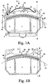
- FIG. 1A shows a brake pad 2 according to an embodiment of the present invention.
- the brake pad has a lip 20, which projects beyond the indicated by the dashed line 10 brake disc from the outside in the installed state. By the lip 20 of the gap between the brake disc 10 and the friction linings 4 is covered and protected against ingress of dirt.
- a region 44 is further shown in dashed lines.
- the region 44 indicates an area where a lip of an associated brake pad may be located (which would extend parallel to it in the figure above the plane of the drawing).
- the brake lining 2 may have recesses in the region 44 in order to receive the lip of the opposing friction lining when the friction lining is worn.
- the recess can also be designed as a breakthrough.
- the support plate of the friction lining has at the upper edge a circumferential lip 20 with an inner radius ri and an outer radius ra, wherein ri is slightly larger than the diameter of the brake disc.
- ra is chosen such that a sufficient strength of the web is present.
- a circumferential lip is also mounted on the upper edge in the designated 44 area, which has an inner radius Ri and an outer radius Ra, wherein Ri is slightly larger ri selected so that the two circumferential lips can dive each other during the braking process ,
- Ri is slightly larger ri selected so that the two circumferential lips can dive each other during the braking process
- the brake lining may further comprise a support plate 6, and friction linings 4 have.
- the friction linings know with the friction surface 5 in the direction of the brake disc.
- the friction surface 5 is intended to achieve the braking effect by the friction with the brake sliding.
- the support plate 6 has receiving elements 36 for a hold-down spring 30 at one end.
- the hold-down spring 30 is shown as a leaf spring.
- the hold-down spring 30 serves to prevent the brake pad 2 beats against the guides 28, the lining shaft of a caliper during movement of the chassis and this damage.
- the hold-down spring 30 is secured in the figure by a locking element 24 which prevents the entire brake pad 2 from falling upwards.
- the leaf spring 30 shown in the drawing can for example be supplemented or replaced by coil spring elements.
- the support plate 6 also has receiving elements 34 for accessories.
- a wear sensor 38 is screwed by means of a nut 39.
- the wear sensor 38 can also be arranged in the friction lining 4 or between the friction lining 4 and the carrier plate 6.
- the accessories can also be integrated into the brake pad 2 during the production of carrier plate 6 and friction lining 4.
- both the support plate 6 and the friction lining 4 can be made of the same material, which also has the advantage that even if the friction lining 4 is completely used up, the support plate 6 does not damage the brake disc, since they made of the same material.
- Figure 1B shows a simpler embodiment of a brake pad 2.
- the brake pad 2 has a lip 20 which, however, is divided in contrast to that shown in Figure 1A. Due to the arrangement of the lip 20 in a nested arrangement only one embodiment of the brake pad can be used. Thereby, e.g. For small series, the expense of molds and tools are halved.
- the shown version of a brake pad can be a bit more complicated during assembly, if the lips overlap even with new brake pads, since then both brake pads must be mounted at the same time. However, this can be avoided by using elastic lips which slide past each other during assembly.
- the area 44 shown in dashed lines also denotes an area on which a lip of an associated brake pad can be located.
- other elements 26 are provided as a receptacle for a lock in Figure 1B.
- the receptacles 26 for locking are shown in phantom to indicate that they need not necessarily be present.
- the reference numerals 4 designate the friction linings
- the reference numeral 6 designates the carrier plate
- the broken line designated by 10 designates the location of the brake disc.
- FIGS. 1A and 1B the arrow D indicates the viewing direction of FIGS. 2A and 2B, and the line B-B shows a sectional plane for FIGS. 3a and 3B.
- FIGS. 2A and 2 B show plan views of a disc brake according to the prior art and according to the present invention from the radial direction. Both figures together is the brake disk 10, which is encompassed by a brake caliper 12.
- the brake caliper 12 can be essentially subdivided into the parts of the application unit 14, counter-holding 16 and the connecting webs 18.
- the application unit 14 is equipped with two brake cylinders 22 in the present example with two brake cylinders.
- the brake pads 2 are located in an opening 8 for mounting the brake pads 2. The opening is highlighted by a particularly wide stroke width.
- the brake pads are secured by means of locking elements 24 in the brake caliper 12. Hold-down springs are not shown in FIGS. 1B to 4 for the sake of clarity.
- the gaps between the friction linings (shown dotted) and the brake disc 10 can not be viewed through the mounting opening 8.
- dirt particles and liquids can not readily penetrate through the opening 8 in the gap between the friction lining and brake disk 10, since the direct path is laid through the lips 20.
- FIGS 3A and 3B are partial cross-sectional views of the prior art disc brakes illustrated in Figures 2A and 2B, respectively, according to the present invention. Both figures together is the brake disc 10 which is attached to a shaft 11, and is encompassed by a brake caliper 12.
- the brake caliper 12 can be essentially subdivided into the parts of the application unit 14, counter-holding 16 and the connecting webs 18.
- the application unit 14 is equipped with brake cylinders 22 with brake pistons 22 in the present example.
- the brake pads 2 are located in an opening 8 for mounting the brake pads 2, and are held by means of the guides 28 in place and locked by means of the elements 24 their place.
- FIG. 3A shows a view, partially cut away along the line AA, of the disk brake of FIG. 2A of the prior art.
- the gaps between the friction linings 4 and the brake disk 10 can be viewed through the mounting opening 8 from above.
- dirt particles and liquids can easily penetrate from above through the opening 8 in the gap / gap between the friction lining 4 and brake disc 10 and in which Cause problems described in the introduction.
- the lateral surface of the brake disc 10 is designated by the reference numeral 25.
- FIG. 3B shows a partially sectioned view of the disc brake of FIG. 2B along line B-B.
- the gaps between the friction linings 4 and the brake disc 10 can not be viewed through the mounting opening 8 from above.
- no dirt particles and liquids from the top can penetrate through the opening 8 in the gap between the friction lining 4 and brake disk 10, since the direct path is blocked by the lips 20.
- FIGS. 4A to I respectively show particular embodiments of the brake pad as a detail C of FIG. 3B.
- FIGS. 4A to 4I in order to achieve greater clarity, the representation of the brake caliper has been completely omitted and the representation of the brake disc has been omitted.
- a brake lining set as shown in Figures 1A, 2B and 3B.
- the brake lining set in this case has two brake pads 2 on which in the illustrated embodiment, a support plate 6, a friction lining and each have at least one lip 20. Furthermore, the brake pads in this embodiment recordings for a lock 28.
- Part 4C essentially represents a combination of the lips of Figs. 4A and 4B, which is further provided with two lips 32 for the protection of application devices. This would mean that the application devices would be in the drawing on the right side.
- the lips 32 can also be the clamping devices of the disc brake are protected against contamination.
- Part 4D illustrates an embodiment in which the lips are nested. Furthermore, the brake pads (arranged here in the support plate) recesses 44. These recesses 44 make it possible to make the lips longer, and thus to ensure a mutual overlap of the lips when new, even with thick friction linings and thin brake discs.
- Part 4E represents a brake lining set, in which only one brake pad has a lip, and the other brake pad 3 has an opening 44.
- the lip can be made much higher. This construction is particularly useful when the brake pad 3 is used on the side of the application device in the brake caliper. This construction makes it particularly easy to integrate a wear indicator into the lip. For example, by markings on the lip indicate that the brake pad must be replaced when the mark, for example. becomes visible behind the second brake pad, or even disappears in the second pad.
- Part 4F represents a brake pad set, in which the two brake pads are connected by a common lip 46/48.
- the lip has two different areas, which differ in their strength.
- the base member 48 of the connection lip is substantially rigid to give the lip a defined shape.
- the central portion 46 is substantially elastic, or movable, so that the brake pads can move each other.
- This lip may for example be made of an elastomer which is made thicker on the base elements 48, and in the middle portion 46 is thinner and thus elastic executed.
- the connection lip may also be made of a composite material, such as a fibrous tissue, which is embedded in the base elements 48 and in the central portion 46 untreated and movable.
- the parts 4G to 41 represent the operation of the lips in a disc brake whose friction linings are subject to wear.
- Part 4G represents medium wear.
- Part 4I represents a completely worn set of brake pads that should be replaced. As can be clearly seen in the drawing, the gap between friction lining and brake disc is protected against contamination and dirt in every state of wear.
- the lip is preferably attached to a backing plate of the brake pad.
- the lip can also be formed directly from the material of which the carrier plate consists. If the support plate is made of cast iron, for example, the lip can be formed directly during casting. But the lip can also be formed from the material of which the friction lining consists. It is even possible to form both the lip and the support plate and the friction lining of a material.
- the lip does not complete the friction lining to the brake disc seals, and it may well happen that in an SUV wading through water, such as water or mud between friction lining and brake disc can come.
- the fact that the lip generally does not rest on the brake disc, but also the frictional resistance of the brake is reduced, if not braked.
- the brake lining can also be used for internally ventilated brake disks without suppressing the airflow in the interior of the brake disk.
- the invention provides a brake pad for disc brakes.
- the brake pad are a carrier plate and a friction lining, and in this case the carrier plate and the friction lining can be made of the same material.
- the brake lining may further comprise receiving elements for hold-down springs.
- the brake lining or the friction lining and the carrier plate may consist of all friction lining materials known to the person skilled in the art.
- friction linings made of sintered materials or thermosets are produced in the composite material.
- Sintered materials usually consist of mixtures of ferrous and non-ferrous metals.
- Thermosets can be made from phenolic resins, epoxy resins, etc.
- the thermosets are reinforced to optimize the material properties with fibers and other fillers.
- the fibers may be e.g. Natural, mineral, polymer, metal, aramid and / or carbon fibers.
- the fibers can either be fibrous, as wood chips, spun, interwoven, entangled and / or, for example, processed as a flow.
- Metallic fillers may be, for example, ferrous or non-ferrous metals, such as Fe, Sn, Zn, Ni, Ag, Al, Mn and / or Mn.
- Non-metallic fillers may be, for example, minerals such as calcium hydroxide, barite, rubber and / or vermiculite.
- the brake pad further comprises a heat insulation.
- This heat insulation may be contained directly in the material of the brake pad or be located as a separate layer in or on the brake pad.
- the exact form of the thermal insulation is not important, it may e.g. be formed by incorporated air pockets, special example sponge-like structures or other materials.
- the disc brake, the caliper, the brake pads can be controlled hydraulically, pneumatically, electrically, magnetically, electromechanically or mechanically. It should be noted that the disc brake according to the invention is suitable for both externally-saddle and for internal-caliper disc brakes. In investigatingsattel- disc brakes engages the Brake caliper in a known manner from the outside via the brake disc. For caliper disc brakes, the caliper engages from the inside over the brake disc.
- the brake pads according to the invention can be applied to both fixed caliper and floating caliper disc brakes.
- the brake linings according to the invention are suitable both for single-piston and for multi-piston brake calipers. The invention is not limited to use with a particular brake disc.
- the brake pad according to the invention can be used together with simple, openwork, grooved, structured, curved, and / or ventilated brake discs.
- the brake disc can be fixed or floating. Even the use in a multi-disc brake is conceivable.
- the above-mentioned fluid cooling can be carried out, for example, in truck as a Preßluftkühlung, in the example of the pneumatic system of the brake system, a secured memory is filled, which cools the brake, or parts of the brake if necessary by compressed air.
- the brakes can be connected to the existing or separate cooling circuit, such as for oil or cooling water.
- the disc brake, brake caliper and brake pad can be used in any technical field in which rotational movements are to be delayed, namely in all automotive applications, in land, rail, water and air vehicles, in which waves and wheels must be braked.
- Other applications include brakes for machinery, engines, rotors, wind turbines, rides and so on.
Landscapes
- Engineering & Computer Science (AREA)
- General Engineering & Computer Science (AREA)
- Mechanical Engineering (AREA)
- Braking Arrangements (AREA)
Claims (11)
- Patin de frein (2) sur un frein à disque pourvu d'un disque de frein (10), le patin de frein (2) comprenant une plaque porteuse (6) et au moins une garniture de friction (4) avec au moins une surface de friction (5) tournée vers le disque de frein (10) et avec une protection de patin de frein (20) qui est agencée de manière à dépasser au-delà de la surface de friction (5) de la garniture de friction (4) et qui s'étend ainsi, dans l'état monté, jusque dans la zone de la surface enveloppe (25) du disque de frein (10) et qui recouvre depuis l'extérieur, à l'encontre d'un encrassement, un intervalle formé entre le disque de frein (10) et la surface de friction (5),
caractérisé en ce que la protection de garniture de friction (20) est réalisée d'un seul tenant avec la plaque porteuse (6). - Patin de frein (2) selon la revendication 1, caractérisé en ce que la protection de garniture de friction (20) est agencée sur le patin de frein (2) de manière à être disposée, dans l'état monté, en étant emboîtée avec une protection de garniture de friction (20) d'un patin de frein opposé.
- Patin de frein (2) selon l'une des revendications précédentes, caractérisé en ce que la protection de garniture de friction (20) comprend au moins une lèvre on caoutchouc ou en un matériau d'élasticité similaire.
- Patin de frein selon l'une des revendications précédentes, caractérisé en ce que le patin de frein présente au moins un évidement (44) qui convient pour recevoir au moins une protection de garniture de friction (20) d'un patin de frein opposé.
- Patin de frein (2) selon l'une des revendications précédentes, caractérisé en ce que la protection de garniture de friction (20) comprend au moins une lèvre réalisée sensiblement rigide.
- Patin de frein (2) selon l'une des revendications précédentes, caractérisé en ce que la protection de garniture de friction (20) est formée par au moins une partie séparée qui est reliée d'un seul tenant à la plaque porteuse du patin de frein.
- Patin de frein (2) selon l'une des revendications précédentes, caractérisé en ce que la protection de garniture de friction (20) repose, dans l'état monté, sur la surface enveloppe (25) du disque de frein (10).
- Jeu de patins de frein comportant au moins deux patins de frein (2, 3) d'un frein à disque, caractérisé en ce que l'un au moins des patins de frein (2, 3) est un patin de frein (2) selon l'une des revendications 1 à 7.
- Jeu de patins de frein selon la revendication 8, caractérisé en ce que les dispositifs de protection de garniture de friction (20) des patins de frein respectifs (2) sont agencés en étant emboîtés dans l'état monté.
- Jeu de patins de trein selon l'une ou l'autre des revendications 8 et 9, caractérisé en ce que les deux patins de frein (2) sont réalisés sensiblement identiques.
- Jeu de patins de frein selon l'une des revendications 8 à 10, caractérisé en ce que l'un au moins des patins de frein (2, 3) du jeu de patins de frein présente au moins un évidement (44) qui convient pour recevoir au moins une protection de garniture de friction (20) d'un autre patin de frein du jeu de patina de frein.
Applications Claiming Priority (2)
| Application Number | Priority Date | Filing Date | Title |
|---|---|---|---|
| DE10222110 | 2002-05-17 | ||
| DE10222110A DE10222110B4 (de) | 2002-05-17 | 2002-05-17 | Bremsbelag mit Schutzlippe für Scheibenbremse |
Publications (3)
| Publication Number | Publication Date |
|---|---|
| EP1363039A2 EP1363039A2 (fr) | 2003-11-19 |
| EP1363039A3 EP1363039A3 (fr) | 2004-06-30 |
| EP1363039B1 true EP1363039B1 (fr) | 2006-03-29 |
Family
ID=29265351
Family Applications (1)
| Application Number | Title | Priority Date | Filing Date |
|---|---|---|---|
| EP03009347A Expired - Lifetime EP1363039B1 (fr) | 2002-05-17 | 2003-04-24 | Patin de frein à disque avec lèvre protectrice |
Country Status (5)
| Country | Link |
|---|---|
| US (1) | US6932199B2 (fr) |
| EP (1) | EP1363039B1 (fr) |
| BR (1) | BR0301362A (fr) |
| DE (2) | DE10222110B4 (fr) |
| ES (1) | ES2256610T3 (fr) |
Families Citing this family (18)
| Publication number | Priority date | Publication date | Assignee | Title |
|---|---|---|---|---|
| AUPS066802A0 (en) * | 2002-02-21 | 2002-03-14 | Pbr Australia Pty Ltd | Improved disc brake caliper |
| US7261188B2 (en) * | 2005-04-18 | 2007-08-28 | Shimano Inc. | Bicycle brake caliper assembly |
| DE102006018269A1 (de) * | 2006-04-20 | 2007-10-25 | Dr.Ing.H.C. F. Porsche Ag | Schutzvorrichtung für eine Teilscheibenbremse |
| US7963376B2 (en) * | 2007-04-17 | 2011-06-21 | Joseph Gelb | System for cooling a disc brake rotor and collecting brake pad waste |
| DE102007049981B4 (de) * | 2007-10-18 | 2009-07-30 | Knorr-Bremse Systeme für Nutzfahrzeuge GmbH | Bremsbelag einer Scheibenbremse |
| US8281907B2 (en) * | 2007-12-03 | 2012-10-09 | Honeywell International Inc. | Brake assembly having multi-piece core and replaceable friction surfaces |
| DE102008008308A1 (de) * | 2008-02-07 | 2009-08-13 | Knorr-Bremse Systeme für Nutzfahrzeuge GmbH | Scheibenbremse, insbesondere für ein Nutzfahrzeug |
| DE102009023104C5 (de) * | 2008-06-05 | 2013-08-22 | Wabco Radbremsen Gmbh | Scheibenbremse, insbesondere für Nutzfahrzeuge, sowie Abdeckung einer solchen Scheibenbremse |
| US8191691B2 (en) | 2008-10-20 | 2012-06-05 | Joseph Gelb | Disc brake debris collection system |
| DE102010043320A1 (de) * | 2010-11-03 | 2012-05-03 | Continental Teves Ag & Co. Ohg | Vorrichtung und Verfahren zur Ermittlung einer Maßgröße für eine wirkende Bremskraft oder Reibkraft an einer Scheibenbremse |
| US9017462B2 (en) | 2012-01-09 | 2015-04-28 | Joseph Gelb | Self adjusting filter mass area that produces extended filter life and uniform static pressure throughout |
| DE102012004606A1 (de) * | 2012-03-02 | 2013-09-05 | Knorr-Bremse Systeme für Schienenfahrzeuge GmbH | Bremsbelag für eine kolbenbetätigte Scheibenbremse eines Schienenfahrzeuges oder eines Nutzfahrzeuges |
| US10316912B2 (en) * | 2014-04-08 | 2019-06-11 | Freni Brembo S.P.A. | Disc brake pad, spring for disc brake caliper and disk brake caliper assembly |
| US9726243B2 (en) * | 2015-03-20 | 2017-08-08 | Bendix Spicer Foundation Brake Llc | Disc brake pad retention system and mounting method |
| US9982729B2 (en) * | 2016-06-21 | 2018-05-29 | Nissan North America, Inc. | Brake pad |
| US9982730B2 (en) * | 2016-06-21 | 2018-05-29 | Nissan North America, Inc. | Brake pad |
| US10591003B2 (en) | 2017-06-16 | 2020-03-17 | Polaris Industries Inc. | Brake assembly shield and scraper |
| DE102022203847A1 (de) * | 2022-04-19 | 2023-10-19 | Hl Mando Corporation | Bremsbelag mit einem relativ zu einem Reibmaterialbelag vorstehenden Abstandshalter |
Family Cites Families (10)
| Publication number | Priority date | Publication date | Assignee | Title |
|---|---|---|---|---|
| US3433328A (en) * | 1966-10-13 | 1969-03-18 | Kelsey Hayes Co | Disk brake assembly and pivotal support means therefor |
| US3884332A (en) * | 1974-03-14 | 1975-05-20 | Dayton Walther Corp | Disc brake with cantilevered torque receiving members |
| JPS5296189U (fr) * | 1976-01-19 | 1977-07-19 | ||
| DE2653607A1 (de) * | 1976-11-25 | 1978-06-01 | Teves Gmbh Alfred | Teilbelagscheibenbremse mit schmutzabstreifer |
| DE2804209A1 (de) * | 1978-02-01 | 1979-08-02 | Kloeckner Humboldt Deutz Ag | Teilbelagscheibenbremse, insbesondere fuer eine getriebewelle und/oder die achsantriebswelle eines land- und/oder bauwirtschaftlich nutzbaren kraftfahrzeuges |
| GB2173267A (en) * | 1985-04-04 | 1986-10-08 | Don International Limited | Disc brake assembly |
| DE8615015U1 (de) * | 1986-06-04 | 1987-10-01 | Lucas Industries P.L.C., Birmingham, West Midlands | Blattfeder zum Niederhalten der Belag-Tragplatte einer Scheibenbremse |
| DE19519940B4 (de) * | 1995-06-02 | 2004-09-02 | Tmd Friction Europe Gmbh | Verfahren zur Herstellung von Bremsbacken |
| DE19705836B4 (de) * | 1997-02-15 | 2006-09-21 | Continental Teves Ag & Co. Ohg | Bremsbacke und Verfahren zu ihrer Herstellung |
| DE19850257C2 (de) * | 1998-10-31 | 2002-09-19 | Daimler Chrysler Ag | Scheibenbremsenschutz einer einen Reibring aufweisenden Scheibenbremse eines Kraftfahrzeugrades mit durchbrochener Felgenschüssel |
-
2002
- 2002-05-17 DE DE10222110A patent/DE10222110B4/de not_active Expired - Fee Related
-
2003
- 2003-04-24 ES ES03009347T patent/ES2256610T3/es not_active Expired - Lifetime
- 2003-04-24 EP EP03009347A patent/EP1363039B1/fr not_active Expired - Lifetime
- 2003-04-24 DE DE50302781T patent/DE50302781D1/de not_active Expired - Lifetime
- 2003-05-06 BR BR0301362-6A patent/BR0301362A/pt not_active Application Discontinuation
- 2003-05-15 US US10/439,097 patent/US6932199B2/en not_active Expired - Fee Related
Also Published As
| Publication number | Publication date |
|---|---|
| EP1363039A3 (fr) | 2004-06-30 |
| BR0301362A (pt) | 2004-08-24 |
| ES2256610T3 (es) | 2006-07-16 |
| EP1363039A2 (fr) | 2003-11-19 |
| DE50302781D1 (de) | 2006-05-18 |
| US20040026188A1 (en) | 2004-02-12 |
| DE10222110A1 (de) | 2004-01-08 |
| DE10222110B4 (de) | 2006-02-09 |
| US6932199B2 (en) | 2005-08-23 |
Similar Documents
| Publication | Publication Date | Title |
|---|---|---|
| DE10222110B4 (de) | Bremsbelag mit Schutzlippe für Scheibenbremse | |
| DE69233511T2 (de) | Bremsvorrichtung | |
| DE3318372A1 (de) | Staubkappe fuer eine betaetigungszylinder-kolben-anordnung bei scheibenbremsen | |
| DE10341095B4 (de) | Scheibenbremse, insbesondere für ein Nutzfahrzeug | |
| EP2304266A1 (fr) | Frein à disque, en particulier pour véhicule utilitaire | |
| DE102015116607A1 (de) | Gedämpfte Bremskomponenten und Verfahren zu deren Herstellung | |
| DE102012203162A1 (de) | Kolben für einen Bremssattel einer Scheibenbremse | |
| DE10133579A1 (de) | Scheibenbremse mit integriertem Bremsbelag | |
| DE69803890T2 (de) | Scheibenbremse | |
| EP4278110B1 (fr) | Ensemble de frein à disque et filtre à particules de poussière de frein | |
| EP1799519B1 (fr) | Procede et agencement pour produire un ensemble rotor/moyeu de roue | |
| DE102021215051B4 (de) | Trommelbremse, bestehend aus zwei oder mehr Teilen, die durch isolierendes Material verbunden sind | |
| DE102012012830A1 (de) | Scheibenbremse eines Kraftfahrzeugs | |
| DE102019200742A1 (de) | Schutzblech für eine Scheibenbremse sowie Scheibenbremse | |
| DE10103969B4 (de) | Antriebseinheit für ein Flurförderzeug | |
| DE102018126957A1 (de) | Bremssystem, Achsträgereinheit für ein niederfluriges Fahrzeug, niederfluriges Fahrzeug mit einer derartigen Achsträgereinheit und Antriebseinheit | |
| DE102010048327A1 (de) | Selbstverstärkende Scheibenbremse | |
| DE112022003483T5 (de) | Nockenwellen-drehsensor-montageanordnung | |
| EP1610027A1 (fr) | Dispositif de refroidissement pour frein à disque. | |
| DE29823591U1 (de) | Scheibenbremse für Fahrzeuge | |
| EP4118355A1 (fr) | Frein de véhicule automobile comprenant une configuration d'interface pour un composant supplémentaire rapporté | |
| EP3783243A1 (fr) | Actionneur électromécanique de frein pour un frein à disque | |
| DE102004018265A1 (de) | Radbremse für Kraftfahrzeuge | |
| EP4560163A1 (fr) | Garniture de frein pour un frein à tambour de véhicule | |
| EP0155530B1 (fr) | Installation pour signaler l'usure de garniture de frein d'un frein pour véhicules automobiles commandé hydrauliquement |
Legal Events
| Date | Code | Title | Description |
|---|---|---|---|
| PUAI | Public reference made under article 153(3) epc to a published international application that has entered the european phase |
Free format text: ORIGINAL CODE: 0009012 |
|
| AK | Designated contracting states |
Kind code of ref document: A2 Designated state(s): AT BE BG CH CY CZ DE DK EE ES FI FR GB GR HU IE IT LI LU MC NL PT RO SE SI SK TR |
|
| AX | Request for extension of the european patent |
Extension state: AL LT LV MK |
|
| PUAL | Search report despatched |
Free format text: ORIGINAL CODE: 0009013 |
|
| AK | Designated contracting states |
Kind code of ref document: A3 Designated state(s): AT BE BG CH CY CZ DE DK EE ES FI FR GB GR HU IE IT LI LU MC NL PT RO SE SI SK TR |
|
| AX | Request for extension of the european patent |
Extension state: AL LT LV MK |
|
| 17P | Request for examination filed |
Effective date: 20040713 |
|
| 17Q | First examination report despatched |
Effective date: 20040915 |
|
| AKX | Designation fees paid |
Designated state(s): DE ES FR GB IT SE |
|
| GRAP | Despatch of communication of intention to grant a patent |
Free format text: ORIGINAL CODE: EPIDOSNIGR1 |
|
| GRAS | Grant fee paid |
Free format text: ORIGINAL CODE: EPIDOSNIGR3 |
|
| GRAA | (expected) grant |
Free format text: ORIGINAL CODE: 0009210 |
|
| AK | Designated contracting states |
Kind code of ref document: B1 Designated state(s): DE ES FR GB IT SE |
|
| REG | Reference to a national code |
Ref country code: GB Ref legal event code: FG4D Free format text: NOT ENGLISH |
|
| REF | Corresponds to: |
Ref document number: 50302781 Country of ref document: DE Date of ref document: 20060518 Kind code of ref document: P |
|
| REG | Reference to a national code |
Ref country code: SE Ref legal event code: TRGR |
|
| GBT | Gb: translation of ep patent filed (gb section 77(6)(a)/1977) |
Effective date: 20060512 |
|
| REG | Reference to a national code |
Ref country code: ES Ref legal event code: FG2A Ref document number: 2256610 Country of ref document: ES Kind code of ref document: T3 |
|
| ET | Fr: translation filed | ||
| PLBE | No opposition filed within time limit |
Free format text: ORIGINAL CODE: 0009261 |
|
| STAA | Information on the status of an ep patent application or granted ep patent |
Free format text: STATUS: NO OPPOSITION FILED WITHIN TIME LIMIT |
|
| 26N | No opposition filed |
Effective date: 20070102 |
|
| PGFP | Annual fee paid to national office [announced via postgrant information from national office to epo] |
Ref country code: GB Payment date: 20100312 Year of fee payment: 8 |
|
| PGFP | Annual fee paid to national office [announced via postgrant information from national office to epo] |
Ref country code: ES Payment date: 20100420 Year of fee payment: 8 Ref country code: FR Payment date: 20100420 Year of fee payment: 8 |
|
| PGFP | Annual fee paid to national office [announced via postgrant information from national office to epo] |
Ref country code: DE Payment date: 20100430 Year of fee payment: 8 Ref country code: IT Payment date: 20100422 Year of fee payment: 8 |
|
| PGFP | Annual fee paid to national office [announced via postgrant information from national office to epo] |
Ref country code: SE Payment date: 20100407 Year of fee payment: 8 |
|
| REG | Reference to a national code |
Ref country code: SE Ref legal event code: EUG |
|
| GBPC | Gb: european patent ceased through non-payment of renewal fee |
Effective date: 20110424 |
|
| REG | Reference to a national code |
Ref country code: FR Ref legal event code: ST Effective date: 20111230 |
|
| PG25 | Lapsed in a contracting state [announced via postgrant information from national office to epo] |
Ref country code: DE Free format text: LAPSE BECAUSE OF NON-PAYMENT OF DUE FEES Effective date: 20111101 Ref country code: FR Free format text: LAPSE BECAUSE OF NON-PAYMENT OF DUE FEES Effective date: 20110502 |
|
| PG25 | Lapsed in a contracting state [announced via postgrant information from national office to epo] |
Ref country code: IT Free format text: LAPSE BECAUSE OF NON-PAYMENT OF DUE FEES Effective date: 20110424 Ref country code: GB Free format text: LAPSE BECAUSE OF NON-PAYMENT OF DUE FEES Effective date: 20110424 |
|
| REG | Reference to a national code |
Ref country code: DE Ref legal event code: R119 Ref document number: 50302781 Country of ref document: DE Effective date: 20111101 |
|
| PG25 | Lapsed in a contracting state [announced via postgrant information from national office to epo] |
Ref country code: SE Free format text: LAPSE BECAUSE OF NON-PAYMENT OF DUE FEES Effective date: 20110425 |
|
| REG | Reference to a national code |
Ref country code: ES Ref legal event code: FD2A Effective date: 20130606 |
|
| PG25 | Lapsed in a contracting state [announced via postgrant information from national office to epo] |
Ref country code: ES Free format text: LAPSE BECAUSE OF NON-PAYMENT OF DUE FEES Effective date: 20110425 |